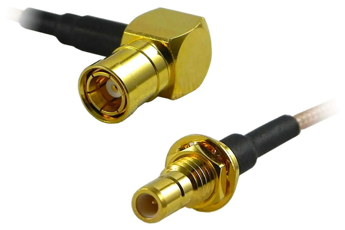
SMB Connector Guide for RF Applications
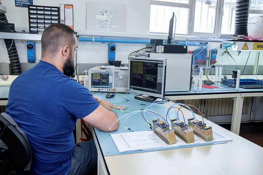
Small RF products often face the same design problem: there is limited space around the circuit, but the connection still needs to remain stable.
A connector that works well on a laboratory bench may not fit inside a compact wireless device. The interface may be...