TNC to BNC Adapter Guide for RF Applications
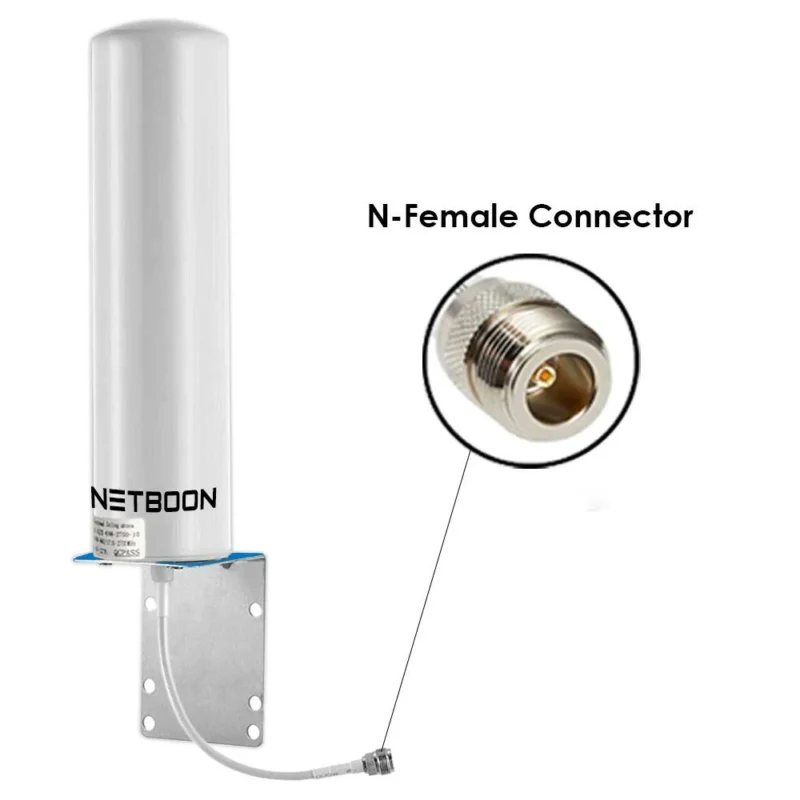
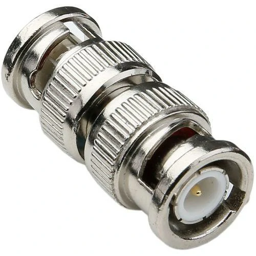
An antenna cable ends with a TNC connector, but the available spectrum analyzer only has a BNC port. Replacing the cable would take time, and changing the instrument interface is not practical. In this situation, a TNC to BNC adapter provides a direct way to connect the two...