
Improve VNA Measurement Accuracy
A VNA report is often the final document used to judge whether an RF cable assembly meets the required specification. However, the numbers shown in the report are not created by the cable alone.
During a real RF measurement, the signal travels through a complete path:
- VNA port
- test cable
- adapter
- connector interface
- cable assembly
- DUT
Any part of this path can influence the measured curve.
This is why two laboratories may test the same RF cable assembly and obtain slightly different S11 or S21 results. The product may be identical, but the calibration method, reference plane position, or connection condition may not be the same.
For suppliers providing RF test reports, the calibration process is not just a preparation step before measurement. It is part of the data credibility behind the report.
Before analyzing VNA results, engineers usually need to understand how connectors, interfaces, and transmission paths affect measurement accuracy. The RF connector guide provides additional information about connector selection and RF signal transmission fundamentals.
How Does SOLT Calibration Make VNA Results Trustworthy?
Why do engineers perform SOLT calibration before RF testing?
In production environments, a VNA is expected to measure the performance of the device under test, not the errors introduced by the testing setup.
This is where SOLT calibration is used.
SOLT represents:
- Short
- Open
- Load
- Thru
These four standards provide known electrical references for the VNA.
Before testing an RF cable assembly, the instrument measures these standards and creates an error correction model.
The purpose is not to change the DUT performance.
A cable assembly that has 1.5 dB insertion loss before calibration will not suddenly become a lower-loss cable after calibration.
The difference is that the VNA can reduce the influence of:
- test cable loss
- connector mismatch
- adapter reflection
- port error
- phase delay
The measurement becomes closer to the actual electrical behavior of the product.
RF Test Example: Where Does Calibration Error Come From?
Consider a common SMA cable assembly test.
The connection path may look like this:
VNA Port
Test Cable→SMA Adapter→SMA Connector→RF Cable Assembly→DUT
If calibration is not correctly performed, the measured result may contain information from the entire chain.
For example:
A damaged adapter may appear as poor return loss.
A loose SMA connection may create unexpected ripple.
A long test cable may increase measured insertion loss.
In some cases, engineers may spend time investigating the cable design when the actual problem comes from the measurement setup.
This situation is common when comparing:
- supplier test reports
- customer incoming inspection results
- third-party laboratory measurements
Keeping the calibration method consistent helps reduce unnecessary discussions about measurement differences.
How Are S11 and S21 Results Affected by Calibration?
Why does S11 require a stable calibration condition?
S11 is related to reflected energy.
In practical RF testing, engineers use S11 data to review:
- impedance matching
- connector transitions
- return loss
- VSWR performance
A change in S11 does not automatically mean that the cable assembly quality has changed.
Before rejecting a product, engineers usually check several details:
| Check Item | Possible Influence |
| Connector cleanliness | Reflection variation |
| Torque consistency | Different contact condition |
| Adapter condition | Additional mismatch |
| Calibration position | Measurement boundary change |
For example, a connector tightened with different torque values may show a different reflection curve, even when the cable itself is unchanged.
This is why repeatable RF testing requires both a calibrated instrument and a controlled connection method.
Why does S21 depend on the complete RF path?
S21 measures transmission behavior between two ports.
For RF cable assemblies, it is usually reviewed for:
- insertion loss
- attenuation
- frequency response
Unlike a simple resistance measurement, RF transmission performance changes with frequency.
Where Should the Calibration Reference Plane Be Located?
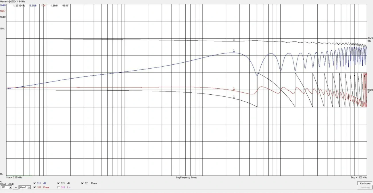
The calibration reference plane decides where the VNA measurement starts.
This point has a direct effect on how engineers interpret the final result.
A simple example:
Setup A
VNA→Test Cable→Adapter→DUT
The measurement may include:
- adapter influence
- test cable characteristics
- additional connector transitions
Setup B
VNA→Test Cable→Calibration Plane→DUT
The measurement boundary moves closer to the actual product.
Neither setup is automatically incorrect.
The key requirement is consistency.
If a supplier tests one batch with an adapter included and another batch with the adapter removed, comparing the two reports may lead to confusion.
For customer projects involving RF cable assemblies, test documentation should normally record:
| Report Item | Purpose |
| VNA model | Identify equipment |
| Calibration method | Confirm measurement process |
| Reference plane | Define test boundary |
| Frequency range | Confirm measurement condition |
| Adapter usage | Understand connection path |
Choose the Right VNA Calibration Kit Before Testing
Does the calibration kit need to match the connector interface?
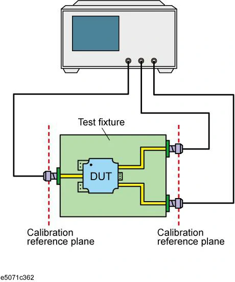
Diagram of a VNA connected to a test fixture, illustrating how calibration reference planes define the measurement boundary around the device under test.
The calibration kit is part of the measurement system.
A connector that can physically connect to the DUT does not always mean the calibration setup is suitable.
Engineers normally check:
- connector interface
- impedance
- frequency range
- calibration definition
- measurement requirement
Common examples:
| Connector Interface | Typical Application |
| SMA | RF cable assemblies and wireless devices |
| N-Type | Communication systems and feeder cables |
| 3.5 mm | Precision RF measurements |
| 2.92 mm | Microwave applications |
Adding unnecessary adapters may make the connection easier mechanically, but each additional transition can introduce another uncertainty source.
For high-frequency testing, reducing unnecessary interfaces usually improves measurement consistency.
How Should Engineers Select the Right VNA Calibration Kit?
A calibration kit is often treated as a small accessory in an RF laboratory.
In reality, it becomes part of the measurement reference.
When a technician connects a calibration standard to the VNA, the instrument uses that connection to understand the electrical behavior of the test path. If the calibration kit does not match the interface or frequency range, the following measurement may look stable but still contain uncertainty.
This situation is especially common when different connector systems are mixed.
For example:
A laboratory may have an SMA cable assembly but use an adapter to connect another type of calibration standard. The connection works mechanically, but the electrical reference has changed.
For RF testing, mechanical connection and electrical performance are two different things.
Which factors should be checked before choosing a VNA calibration kit?
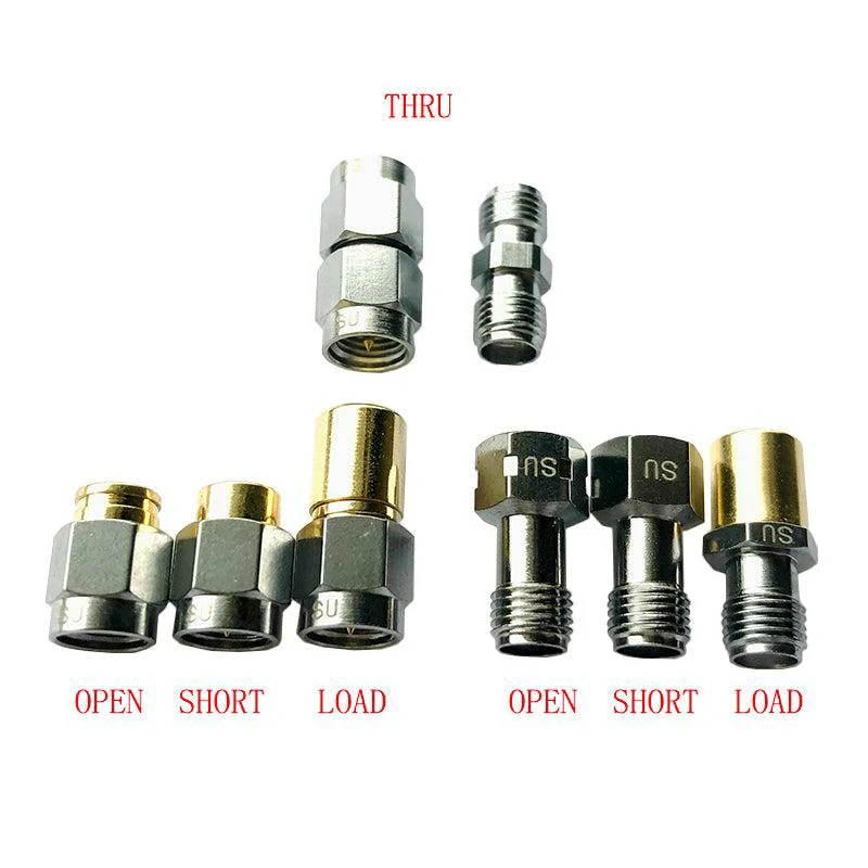
A coaxial VNA calibration kit containing Open, Short, Load, and Thru standards for establishing accurate one-port and two-port RF measurements.
Before starting a measurement, engineers normally confirm several details.
Connector interface
The calibration standard should match the interface being measured.
Common examples:
| Interface | Typical RF Application |
| SMA | RF cable assemblies, antennas, wireless modules |
| N-Type | Communication systems, outdoor RF links |
| 3.5 mm | Precision laboratory measurement |
| 2.92 mm | Microwave and high-frequency testing |
The connector style affects more than physical compatibility.
Different interfaces have different:
- mechanical dimensions
- electrical characteristics
- frequency limitations
- calibration definitions
Adding an adapter between two interfaces may be necessary in some test setups, but it should be considered part of the measurement path.
Frequency coverage
A calibration kit should support the complete frequency sweep.
This point becomes important when testing broadband RF products.
For example:
A cable assembly may be used around 6 GHz, but the VNA sweep may start from a lower frequency and continue beyond the main operating point.
The calibration standard needs to remain valid across that entire range.
Otherwise, the error correction model may not fully represent the actual measurement condition.
Calibration definition file
Modern VNAs often rely on calibration definition data stored inside the instrument.
The data describes the electrical behavior of:
- Short
- Open
- Load
- Thru
Using the wrong definition file can create measurement differences even when the connector physically fits.
For supplier testing, recording the calibration kit model together with the VNA report helps customers understand how the result was obtained.
How Do Short, Open, Load, and Thru Affect SOLT Calibration?
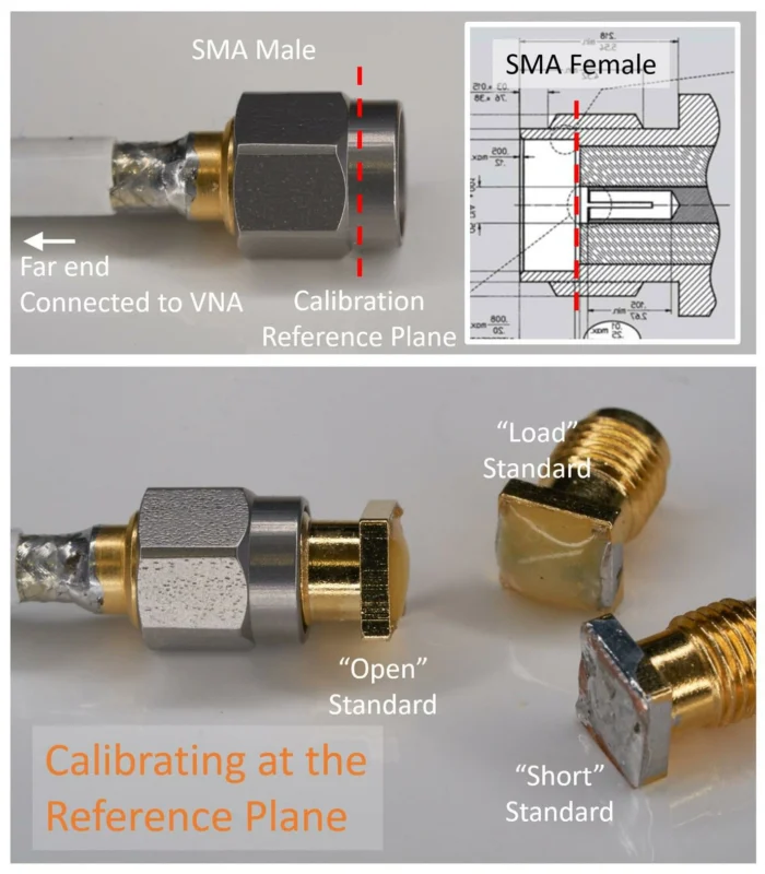
During a SOLT calibration process, each standard has a different role.
The four standards are not interchangeable.
A mistake with one standard can influence the final measurement.
Why is the Short standard used during calibration?
The Short standard provides a known reflection condition.
The VNA uses this reference to understand how the system responds to a strong reflection.
In daily laboratory work, the Short standard is handled carefully because the connector surface directly affects the measurement.
Before calibration, technicians normally check:
- contact surface condition
- connector cleanliness
- mechanical damage
- correct frequency usage
A small particle on the connector surface may not be visible, but it can influence high-frequency measurements.
Why does the Open standard need attention at higher frequencies?
The Open standard provides another reference point for the VNA.
At lower frequencies, its behavior is easier to predict.
As frequency increases, physical details become more important.
The connector structure, calibration definition, and frequency range all affect the result.
This is one reason why RF laboratories avoid mixing calibration standards from different systems unless the compatibility has been confirmed.
Why is the Load standard important for return loss measurement?
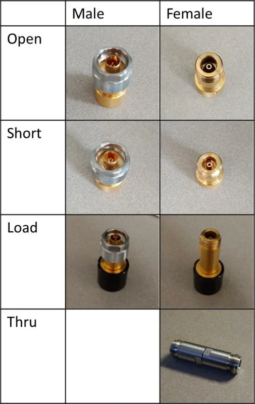
The Load standard represents the matched condition used by the VNA.
A reliable Load reference helps the instrument evaluate reflection behavior correctly.
This directly affects measurements such as:
- return loss
- VSWR
- S11
When a customer reviews an RF cable assembly report, an unexpected return loss change may come from the product, but it may also come from calibration conditions.
Checking the calibration setup before repeating production tests can save unnecessary troubleshooting time.
Why does the Thru standard affect S21 results?
The Thru standard is mainly related to two-port transmission measurement.
It establishes the relationship between the two VNA ports.
This matters when measuring:
- insertion loss
- transmission response
- cable attenuation
For RF cable assemblies, S21 data is often used as one of the key acceptance parameters.
A change in the Thru calibration condition can influence the final transmission curve.
How Can Calibration Problems Change S11 and S21 Results?
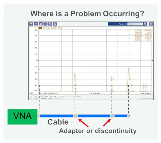
A diagnostic illustration showing how a VNA trace can help locate impedance discontinuities caused by cables, adapters, or connector transitions.
When an RF measurement looks unusual, engineers usually check the setup before changing the product design.
A few common situations appear repeatedly in production testing.
Information Asset: S11 and S21 Error Source Matrix
| Error Source | S11 Influence | S21 Influence | Typical Symptom | Investigation Method |
| Dirty connector | High | Medium | Unexpected ripple | Clean and repeat measurement |
| Wrong calibration kit | High | High | Unstable overall result | Confirm calibration data |
| Adapter added after calibration | High | High | Curve shift | Recalibrate system |
| Damaged test cable | Low | High | Higher insertion loss | Replace reference cable |
| Different torque condition | High | Low | Poor repeatability | Control tightening method |
Why can the same cable show different S11 curves?
This happens during supplier and customer comparison testing.
The cable may be identical.
The difference may come from:
- different calibration plane
- different adapters
- different test cables
- different connector tightening force
A VNA curve is always connected to the conditions under which it was measured.
That is why experienced engineers record the test method together with the result.
Why can adding an adapter change the measurement?
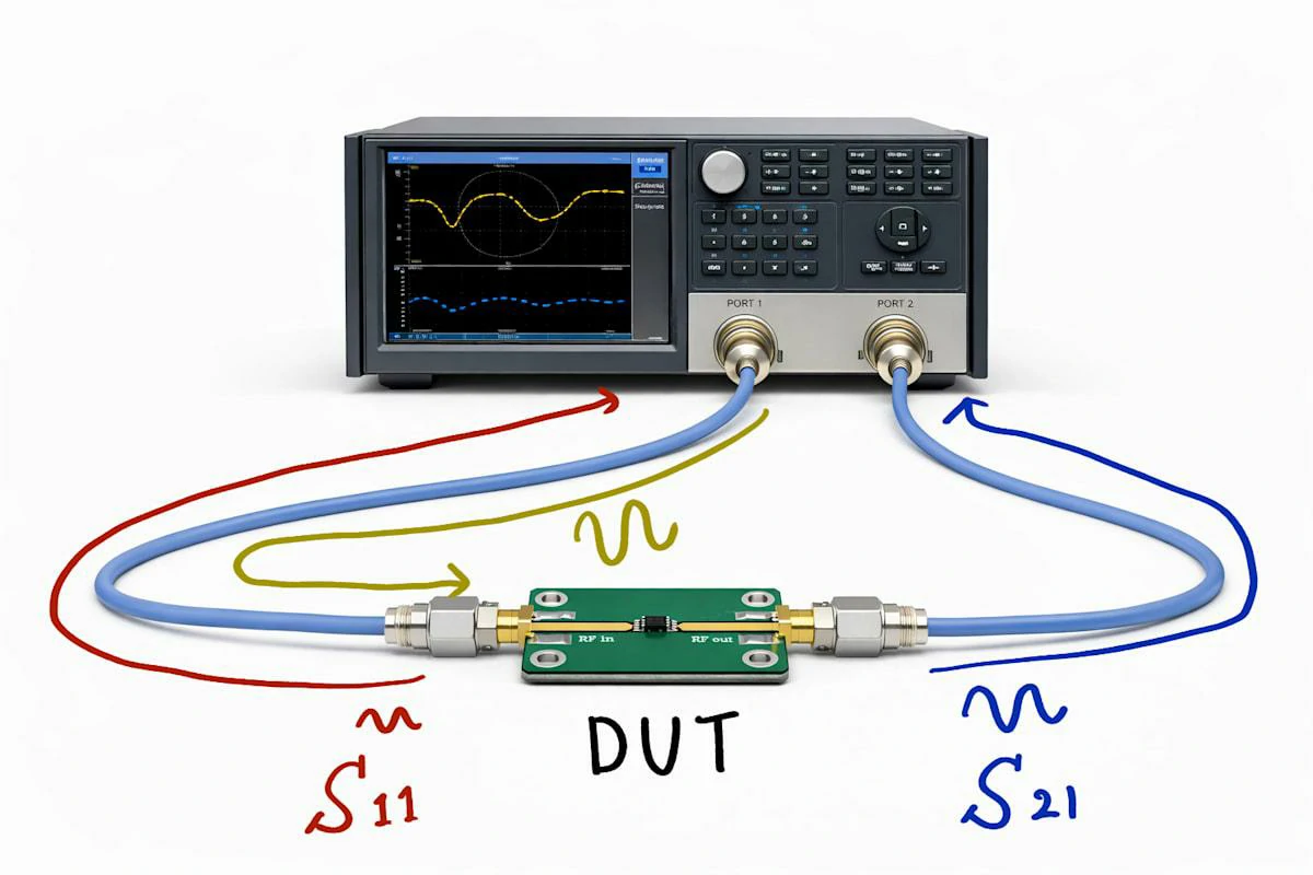
Illustration of a two-port vector network analyzer setup used to measure S11 reflection and S21 transmission performance of a device under test.
An adapter looks simple from a mechanical viewpoint.
Electrically, it creates another RF transition.
After calibration, adding a new adapter changes the measurement path.
The VNA is now seeing a different system.
Possible changes include:
- additional reflection
- extra insertion loss
- phase variation
If the adapter belongs to the final application, it should be included during the defined measurement setup.
If it is only used temporarily, recalibration is usually required.
How Should Engineers Verify Calibration Before Production Testing?
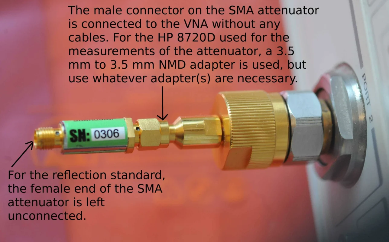
A calibration process should be checked before measuring a large batch of products.
Many RF suppliers use a reference component or known cable assembly for verification.
The purpose is simple:
Confirm that the measurement system is behaving normally.
Use a reference cable before testing production units
A known reference cable can help identify unexpected changes.
Engineers may compare:
- previous S11 curve
- previous S21 response
- frequency behavior
If the reference measurement changes, the production cable should not be judged immediately.
Keep the test setup consistent between batches
For repeated RF cable assembly orders, consistency is important.
The following information should be maintained:
| Test Item | Recommended Record |
| VNA model | Equipment information |
| Calibration method | SOLT or other method |
| Calibration kit | Model and frequency range |
| Adapter usage | Included or excluded |
| Test cable | Identification information |
| Frequency sweep | Measurement range |
A consistent test process makes comparison between shipments much easier.
How Should Suppliers Prepare SOLT Calibration Records for RF Test Reports?
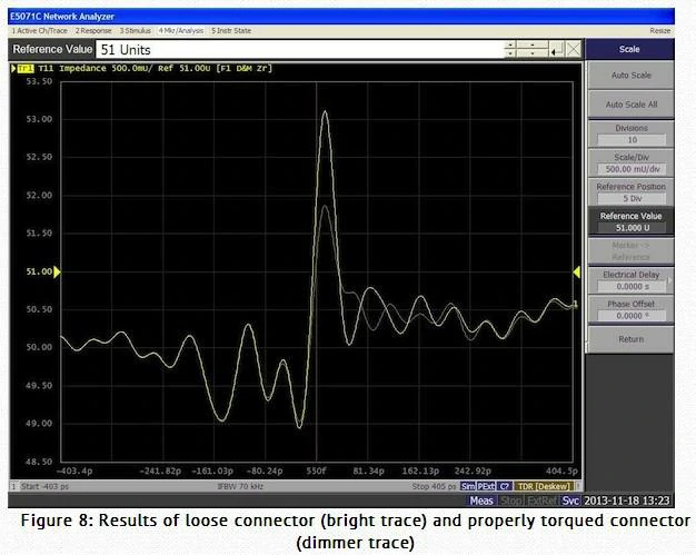
A VNA impedance display demonstrating how an improperly tightened RF connector can create measurement variation and reduce test repeatability.
A customer checking an RF cable assembly usually sees the final VNA curve first.
The curve may show:
- S11 performance
- S21 response
- frequency sweep
- pass or fail judgment
However, the curve alone does not explain how the measurement was completed.
During technical communication between suppliers and customers, the same question often appears:
“Why are the results different from another laboratory?”
The answer is usually not a single parameter.
The test setup matters.
A VNA measurement depends on many details around the DUT:
- calibration position;
- connector interface;
- adapter configuration;
- test cable condition;
- frequency range.
For this reason, a supplier report should include the information behind the curve, not only the final value.
When reviewing RF measurement requirements, engineers often check connector structure and interface selection first. The RF connector guide provides background information for understanding how connector design affects RF performance.
What information helps customers understand a VNA test result?
A practical RF test report normally answers three questions:
What was tested?
How was it measured?
Under what condition was the result obtained?
A simple example:
Product:
SMA male to SMA female cable assembly
Test:
S11 and S21 measurement
Condition:
0–6 GHz sweep with SOLT calibration
Without these details, a number on the report has limited reference value.
Supplier SOLT Calibration Report Checklist
| Item | Information to Record |
| Product model | Cable assembly identification |
| Connector type | Both ends of the assembly |
| Cable specification | Cable structure and length |
| Frequency range | Measurement sweep range |
| VNA model | Testing equipment |
| Calibration method | SOLT or other method |
| Calibration kit | Standard used during calibration |
| Reference plane | Measurement starting point |
| Adapter information | Additional RF transitions |
| S11 result | Reflection performance |
| S21 result | Transmission performance |
| Test date | Measurement record |
How Can Production Teams Keep RF Test Results Consistent?
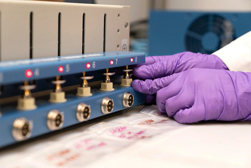
Laboratory production testing of RF connectors using a controlled fixture to verify connector condition and electrical consistency before shipment.
A qualification sample and a production batch are different situations.
During sample evaluation, engineers may spend extra time confirming the setup.
During mass production, the challenge changes.
The measurement process needs to remain stable.
A small change can affect the result:
- replacing a test cable;
- moving the calibration plane;
- changing an adapter;
- using another connector torque method.
The cable assembly may still be identical.
The test condition is different.
Should repeat orders use the same VNA setup?
For long-term supply projects, keeping the same setup helps both sides compare results.
Typical controlled items include:
| Test Element | Control Method |
| VNA setting | Keep the same configuration |
| Calibration method | Use the same procedure |
| Adapter | Record usage |
| Test cable | Avoid unnecessary replacement |
| Connector torque | Maintain consistent operation |
This becomes especially useful when customers review several shipments over time.
A report from six months ago should be comparable with a new report from the same product line.
Why should suppliers save original measurement files?
A PDF report is useful, but the original data provides more details.
Common saved files include:
- Touchstone files;
- VNA screenshots;
- measurement traces;
- calibration records.
These files help when a customer asks:
“Can we compare this batch with the previous shipment?”
Instead of repeating the entire investigation, engineers can review the original measurement condition.
When Should Engineers Perform SOLT Recalibration?
A calibration result belongs to a specific setup.
Once the setup changes, the previous calibration may no longer describe the actual measurement path.
Common examples:
A new adapter is added
The electrical path changes.
The old calibration does not include the new transition.
The test cable is replaced
Different cables may have different loss and phase characteristics.
The frequency range changes
A calibration that works for one frequency range may need verification before another sweep.
The measurement curve becomes unusual
Before blaming the DUT, engineers normally check:
- calibration status;
- connector condition;
- adapter connection;
- test cable condition.
Recalibration Decision Table
| Situation | Recommended Action |
| Adapter added after calibration | Repeat calibration |
| Connector interface changed | Create new setup |
| New frequency range required | Verify calibration |
| Abnormal S11/S21 trace | Check and recalibrate |
| Long storage period | Confirm setup condition |
How Do Higher Frequency RF Applications Change Calibration Requirements?
As frequency increases, small mechanical differences become easier to observe.
This is common in applications around:
- 6 GHz wireless systems;
- RF modules;
- antenna assemblies;
- compact communication devices.
A connector transition that looks insignificant at a lower frequency may affect the measurement near the upper operating range.
Why do extra adapters create more uncertainty?
An adapter is not only a mechanical converter.
Electrically, it creates another interface.
Example:
VNA→Adapter→Cable Assembly→DUT
Compared with:
VNA→Cable Assembly→DUT
The first setup contains an additional transition.
That transition may influence:
- reflection;
- insertion loss;
- phase response.
For SMA applications near higher frequencies, connector capability and frequency margin should be considered during test planning. The SMA connector frequency range guide provides additional reference when selecting SMA interfaces.
Should testing include the complete operating range?
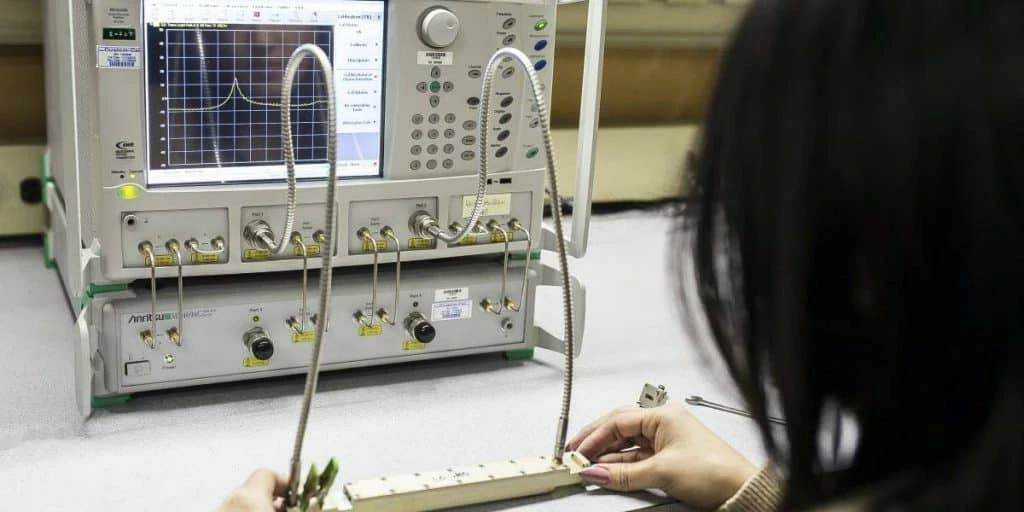
A laboratory VNA setup used to test RF cable assemblies, connector interfaces, and transmission performance across the required frequency range.
A single frequency point cannot show the entire RF behavior.
For a cable assembly rated for a wide frequency range, engineers usually review the complete sweep.
This helps identify:
- increasing loss;
- unexpected peaks;
- reflection changes.
What Should Engineers Check Before Rejecting an RF Cable Assembly?
A failed RF measurement should trigger an investigation.
It should not immediately become a product rejection.
A practical troubleshooting order is usually:
Check the calibration first
Review:
- calibration kit;
- calibration date;
- calibration method;
- reference plane.
Check the RF connections
Inspect:
- connector surface;
- adapter condition;
- mating condition;
- torque consistency.
Check the measurement history
Compare:
- previous batch data;
- current trace;
- test setup changes.
Sometimes the difference is created before the cable reaches the VNA.
FAQ
Why is SOLT calibration used in RF cable testing?
SOLT calibration helps establish a reliable measurement reference before testing RF components. It reduces the influence of the measurement system on the final result.
Can calibration affect S11 and return loss results?
Yes. The calibration condition, reference plane, and connector setup can influence reflection measurements.
Why can two suppliers measure different S21 results?
Different VNA settings, calibration methods, adapters, and test cables can produce different transmission results.
Does adding an adapter require recalibration?
If the adapter becomes part of the measurement path, recalibration is normally recommended.
What should an RF test report include?
A useful report should include product information, VNA details, calibration method, frequency range, and measurement results.
Is SOLT calibration only needed for high-frequency testing?
No. Calibration is useful for RF measurements in general. Higher frequencies simply make setup differences more noticeable.
How can customers compare reports from different suppliers?
The comparison should include both the measurement result and the test condition behind the result.
