
A cable assembly can pass continuity and still be the wrong RF part.
That is where many SMA sourcing problems begin. The drawing says “SMA cable.” The buyer asks for RG58. The prototype radio works on the bench. Then the same assembly is used closer to the upper band, or routed through a tighter enclosure, or measured on a VNA instead of a basic functional test. Suddenly the result looks different: higher VSWR, more loss, unstable readings after the cable is moved.
The connector did not necessarily fail. It may have been selected with too little frequency margin.
The SMA connector frequency range printed on a product page is only one part of the RF path. A 0–6GHz SMA connector, an 18GHz SMA connector, and a precision microwave SMA can share the same familiar threaded interface, but they do not carry the same manufacturing expectations. Geometry control, dielectric fit, contact alignment, cable termination, and inspection standards all affect the finished assembly.
Map Your Highest Operating Frequency Before Picking SMA
Do not start with the product name. Start with the highest frequency the assembly must carry.
“Wi-Fi antenna cable” may mean 2.4GHz only, 5GHz, or a design working close to the 6GHz band. “LTE antenna cable” may be well below 3GHz, or it may sit inside a wider sub-6 wireless system where cable loss becomes more visible. GPS sounds simple because the center frequency is much lower, but a long thin cable with weak shielding can still create practical trouble.
A 0–6GHz SMA connector is a reasonable choice for many commercial RF assemblies. It can work well for GPS leads, 2.4GHz Wi-Fi, many LTE antenna cables, sub-6GHz wireless devices, and short RF test jumpers. The mistake is treating “rated to 6GHz” as proof that every finished cable assembly will behave cleanly up to 6GHz.
It will not.
The connector belongs to a chain: cable type, cable length, termination method, bend radius, adapter count, mating condition, and outgoing inspection. A higher-rated connector cannot rescue a poorly built cable path. At the same time, a well-made 6GHz SMA assembly can be completely suitable for many practical RF systems.
Define the real operating band, not only the device name
A better RF purchase note is not simply:
“SMA cable for Wi-Fi.”
A useful note looks more like:
“SMA male plug cable assembly, 50 ohm, operating up to 5.8GHz, RG58 or RG142 cable, straight termination, VSWR check required.”
That gives the supplier enough information to match the connector body, ferrule, center pin, dielectric support, and inspection method. It also prevents a common sourcing issue: two assemblies that look similar in photos but are not mechanically or electrically equivalent.
For example, a GPS antenna lead at 1.575GHz does not need the same connector margin as a lab jumper swept near 6GHz. A short module-to-panel jumper inside a fixed enclosure does not face the same mechanical stress as a cable installed and removed repeatedly in the field.
Same SMA interface. Different risk.
Separate signal frequency from connector rating
A connector rated to 6GHz is not automatically wrong for a 5GHz system. It may be perfectly acceptable if the cable is short, the termination is clean, and the system has enough tolerance for insertion loss and return loss.
But once the operating frequency sits close to the connector’s upper rating, the buying decision becomes less forgiving. A small crimp defect, loose braid contact, stretched dielectric, extra adapter, or sharp bend near the connector exit may show up in RF performance.
Use the table below as a practical first filter, not as a substitute for test data.
| Highest Operating Frequency | 6GHz SMA Fit | Safer Choice for Test Margin | Main Buying Concern |
| GPS around 1.575GHz | Usually safe | Not usually needed | Cable shielding and routing |
| 2.4GHz Wi-Fi | Usually safe | Optional | Adapter count and cable length |
| 3–4GHz wireless | Usually workable | 18GHz if return loss matters | Cable loss and termination quality |
| 5–6GHz Wi-Fi / RF module | Marginal if poorly built | 18GHz often safer | Low frequency margin |
| Above 6GHz | Not suitable | 18GHz or higher | Connector grade and cable type |
The table explains why the same SMA connector can be a good production choice in one design and a weak choice in another. Frequency rating is a gate. It does not describe the full RF behavior of the cable assembly.
For buyers still comparing coax families, TEJTE’s RG cable guide is a useful reference before fixing the connector and cable combination.
Use SMA-J-3 as a 0–6GHz product example
A typical SMA-J-3 style connector is a good example of a general-purpose RF cable connector. It uses an SMA male plug structure, 50 ohm impedance, and a 0–6GHz working frequency range. A practical version may be built for RG58 or RG142 cable, with a stainless steel nut, gold-plated contact, PTFE insulator, and straight cable termination.
This is not a precision microwave connector. It is the kind of SMA many buyers use for antenna leads, equipment ports, module-to-panel jumpers, and short test cables.
The main requirement is cable fit.
RG58 and RG142 are larger than miniature coaxial cables such as RG316 or RG178. The connector body, center pin, ferrule, dielectric support, and crimp area must match the actual cable. A connector made for a smaller cable should not be substituted just because the front interface is SMA. That mistake can create poor braid contact, weak retention, center conductor stress, or inconsistent impedance at the termination.
A finished SMA cable assembly may look normal from the outside while hiding a termination problem under the ferrule. That is why visual inspection alone is not enough near higher frequencies. Pin alignment, crimp quality, continuity, insulation resistance, and at least a target-frequency RF check matter more as the assembly approaches the upper operating band.
Is a 6 GHz SMA Connector Enough for Wi-Fi, LTE, GPS, and Sub-6 Systems?
In many cases, yes. But the answer depends on margin, not only on the number printed in the listing.
A 0–6GHz SMA connector is usually a practical fit for GPS antenna leads, 2.4GHz Wi-Fi, many LTE antenna cables, short RF jumpers, and general sub-6GHz wireless devices. It is available, cost-effective, mechanically secure, and familiar to most RF buyers.
The risky area is the upper edge. A 5.8GHz Wi-Fi cable using a 6GHz-rated connector may work well in a short, clean assembly. Add a longer RG58 run, two adapters, a right-angle bend, and a loose production tolerance, and the same rating becomes less comforting.
The connector is still “within range.” The assembly may not be.
Match 0–6GHz SMA to common RF applications
A 6GHz SMA connector is commonly used for 2.4GHz Wi-Fi antenna cables, GPS antenna leads, LTE router antennas, RF module jumpers, test fixtures, gateway antennas, and short panel-mount RF cables.
That broad use is the reason 0–6GHz SMA parts remain popular. They solve many real commercial jobs without the cost of higher-frequency precision connectors. For ordinary antenna connection, the customer often needs stable mating, correct impedance, good cable fit, and repeatable assembly quality more than an 18GHz label.
Still, the supplier should know the actual frequency. “Sub-6GHz” is too broad if the project is close to 6GHz and the cable will be measured carefully.
Where 6GHz rating works well
A 6GHz SMA connector works best in a controlled RF path: short cable, limited adapter use, proper cable match, and no severe bending close to the connector body.
A module-to-panel jumper is a typical example. Once installed, the cable stays fixed. The RF path is short. The connector is not constantly mated and unmated. In this environment, a well-built 0–6GHz SMA assembly can be a sensible production choice.
It also works for general-purpose bench cables where the goal is functional RF connection rather than precision measurement. If the test only confirms communication, antenna response, or module operation, a clean 6GHz SMA cable may be enough.
Where 6GHz rating becomes risky
The risk increases when the assembly is used near the top of the rating, measured repeatedly, or installed in a mechanically stressful path.
A cable that passed in an open prototype may perform differently after being routed through a compact enclosure. A bend near the SMA body can disturb the termination. An added adapter can introduce extra mismatch. A longer RG58 cable can add more loss than the buyer expected.
Lab measurement is another case. A 6GHz connector may be rated for the sweep range, but VNA work is less forgiving than a normal antenna connection. If the result depends on stable return loss and repeatable insertion loss, an 18GHz SMA assembly often gives better margin.
That does not mean every Wi-Fi, LTE, GPS, or sub-6 design needs 18GHz SMA. It means the buyer should separate a normal RF connection from a measurement-grade or margin-sensitive RF path.
For a production antenna lead, 6GHz may be enough. For repeatable RF testing near the upper band, it may be the wrong place to save cost.
Where Does 18 GHz SMA Become the Safer Choice?
The jump from a 6GHz SMA connector to an 18GHz SMA connector is not only about using a part at a higher frequency. In many real projects, the reason is less dramatic: the engineer wants less uncertainty.
A system may only operate at 5.8GHz, but the measurement process may need repeatable return loss. A cable may only be used on a sub-6GHz module, but the module is expensive, the test fixture is reused every day, and unstable mating results waste engineering time. In that situation, the 18GHz connector is not being used because the signal is 18GHz. It is being used because the RF path needs better margin.
This is especially common in lab cables, VNA jumpers, microwave benches, radar module test setups, and production fixtures where the same cable is repeatedly connected and disconnected. The connector face, dielectric support, center contact, and mechanical tolerance start to matter more.
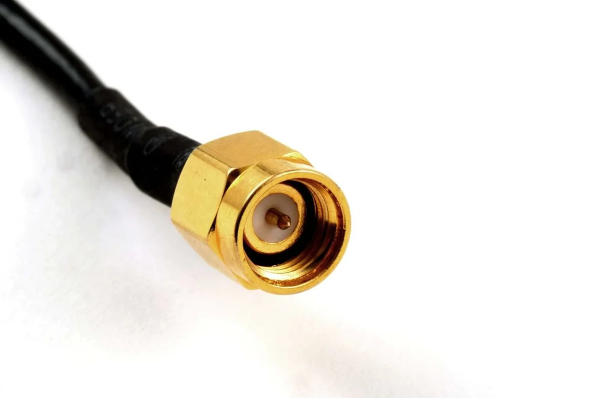
Close-up view of a gold-plated SMA male connector attached to a black coaxial cable. The center pin, internal coupling threads, dielectric support, and cable termination area all influence the usable SMA connector frequency range.
Caption: VNA testing and SMA cable assemblies are useful visuals here because this section is about repeatability, return loss, and connector margin.
Use 18GHz SMA for measurement confidence
A normal antenna cable and a measurement cable do not have the same job.
An antenna cable usually needs to carry enough signal for the system to work within its link budget. A measurement cable needs to avoid becoming the reason the reading changes. That is a much stricter requirement.
For VNA work, a weak SMA assembly may create several problems. Return loss may change after re-mating. Insertion loss may be higher than expected. Cable movement may affect the sweep. Adapter stacks may introduce extra mismatch. Two assemblies with the same written specification may not behave the same.
A better SMA connector cannot remove all cable-related variation, but it reduces one source of error. It also usually comes with better process control. That matters when the cable is not a one-time installation part, but a repeated test tool.
Compare 6GHz, 12.4GHz, 18GHz, and 26.5GHz SMA levels
SMA connectors are often seen in several practical frequency classes. The exact rating depends on the manufacturer, interface design, material control, and assembly method, but buyers commonly encounter 6GHz, 12.4GHz, 18GHz, and 26.5GHz options.
The higher the rated frequency, the less tolerance there is for casual manufacturing. Small geometry differences that are invisible at low frequency can become visible at microwave frequency. The center contact cannot be loose. The dielectric cannot be deformed. The connector body cannot be treated as a generic metal shell.
| SMA Rating Level | Typical Use | Strength | Limitation |
| 0–6GHz | Antenna leads, short RF jumpers, Wi-Fi/LTE/GPS assemblies | Practical, available, cost-effective | Low margin near 6GHz |
| 12.4GHz | Higher-grade RF cables and general microwave use | Better margin than 6GHz | Still depends heavily on cable and termination |
| 18GHz | VNA cables, lab fixtures, microwave modules | Safer for repeatable test work | More expensive; cable may still be the bottleneck |
| 26.5GHz | Precision microwave assemblies | Higher-frequency capability and tighter control | Needs suitable cable, adapters, and inspection |
The table should not be read as “always buy the highest number.” That is an easy way to increase BOM cost without improving the system. If the cable is RG58, long, flexible, and routed through a rough installation path, a 26.5GHz connector will not magically turn it into a microwave-grade assembly.
Avoid over-specifying precision SMA when the cable is the bottleneck
Over-specification happens more often than suppliers admit.
A buyer asks for an 18GHz or 26.5GHz SMA because they believe the higher number means lower loss in every situation. Sometimes it helps. Sometimes the cable dominates the loss long before the connector rating matters.
RG58 is a good example. It is useful, flexible, widely available, and cost-friendly. But for higher-frequency or longer RF paths, cable attenuation can become the main problem. If the assembly is several meters long, the connector frequency rating may not be the limiting factor. The cable loss is.
This is where procurement and engineering should talk before locking the BOM. If the project is a short jumper near 5GHz, upgrading connector grade may help. If the project is a long outdoor run, the cable choice may need to change first.
How Do Cable Type and Termination Limit Real SMA Bandwidth?
The connector gets most of the attention because it is visible. The cable and termination do more of the damage.
A clean SMA interface can still perform poorly if the center conductor is overheated during soldering, the braid contact is uneven, the dielectric is crushed, or the ferrule is crimped with the wrong tool. These are not cosmetic problems. They change impedance at the transition point, and the transition point is exactly where the cable becomes the connector.
For low-frequency work, a rough termination may still pass. At higher frequency, the same small defect can become measurable.
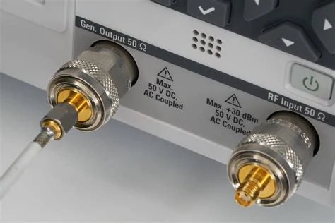
Close-up of the 50-ohm input and output ports on RF test equipment fitted with coaxial adapters. The image illustrates how SMA connectors and cable assemblies can be tested for frequency response, return loss, insertion loss, and repeatability.
Caption: Cable construction, connector termination, and cable length can limit usable RF performance even when the SMA interface itself looks correct.
Cable loss can matter more than connector rating
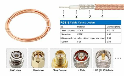
Different coaxial cables behave differently as frequency rises. RG58, RG142, RG316, RG402, and RG405 are not just different names or diameters. They differ in dielectric, shielding, conductor structure, flexibility, heat resistance, and loss.
A flexible cable may be easier to install but less stable under bending. A semi-rigid cable may offer better RF stability but be unsuitable for repeated movement. A cable that works well in a short lab jumper may be a poor choice for a long antenna run.
For general comparison:
| Cable Type | Practical Character | Where It Fits | Watch Point |
| RG58 | Flexible, common, cost-effective | Short RF assemblies, radio, antenna leads | Higher loss at longer length or higher frequency |
| RG142 | Better heat resistance and shielding than basic RG58 | More demanding RF cable assemblies | Less flexible, higher cost |
| RG316 | Small, flexible, common in compact devices | Short internal jumpers, antennas, modules | Not a substitute for larger RG58/RG142 connector bodies |
| RG402 | Semi-rigid, stable RF geometry | Microwave test paths, fixed RF routing | Not suitable for frequent bending |
| RG405 | Smaller semi-rigid microwave cable | Compact microwave assemblies | Requires controlled forming and termination |
The practical question is not “which cable is best?” It is “which cable is best for this length, frequency, bend condition, and inspection requirement?”
For SMA cable assemblies, the wrong answer is usually caused by mixing one good feature with one ignored constraint. A buyer picks RG58 because it is flexible, then expects microwave-level loss. Another buyer picks semi-rigid cable for stability, then routes it like a flexible cable. Both decisions look logical in isolation. Both can fail in use.
Termination quality changes VSWR and insertion loss
The most sensitive area of many SMA cable assemblies is not the threaded interface. It is the transition under the rear body and ferrule.
A good termination keeps the RF geometry as controlled as possible. The center conductor fits the pin correctly. The dielectric is not burned or crushed. The braid has proper contact. The ferrule holds the cable without deforming the structure. The pin is centered and does not shift during mating.
A poor termination may show high VSWR near the target band, unstable insertion loss after bending, weak pull strength, intermittent contact, dielectric recession, center pin misalignment, or poor braid retention.
This is why two cables with the same visible connector and same cable marking can test differently. The assembly process is part of the RF product.
RG58 and RG142 require the correct ferrule and body size
RG58 and RG142 can often use similar SMA connector families because their size class is compatible in many designs. But that does not mean any SMA plug can fit them.
The connector must match the cable outer diameter, dielectric diameter, center conductor size, braid thickness, ferrule inner diameter, crimp hex size, and solder or crimp process.
A connector designed for RG316 is not automatically usable for RG58. The front SMA interface may look the same, but the rear cable-entry structure is different. If the ferrule does not compress correctly, the cable may feel attached but still have poor RF contact or weak mechanical retention.
For repeated orders, this detail should be written into the BOM. “SMA male for RG58/RG142” is better than “SMA male connector.” Adding frequency, impedance, cable type, and termination method reduces the chance that a supplier replaces the connector with a similar-looking but wrong part.
Use This Frequency Margin Table Before Ordering
Frequency margin is not a formal guarantee. It is a practical buying habit.
A connector should not be selected at the exact edge of the operating band unless the full assembly has been tested and the risk is understood. For a simple RF connection, a small margin may be acceptable. For a test lead, production fixture, or low-VSWR system, more margin is usually worth paying for.
A simple formula helps buyers and engineers talk about the same thing:
Frequency Margin Ratio = Connector Rated Frequency ÷ Highest Operating Frequency
For general RF connections, a ratio above 1.2x is often workable. For test leads and repeatable assemblies, 1.5x is a better starting point. For sensitive measurement or low-VSWR applications, 2.0x or more gives more comfort, provided the cable also supports the requirement.
| Application | Highest Frequency | Suggested SMA Rating | Cable Type | Risk Level | Recommended Action |
| GPS antenna lead | 1.575GHz | 6GHz | RG174 / RG316 | Low | Focus on shielding and routing |
| 2.4GHz Wi-Fi cable | 2.4GHz | 6GHz | RG58 / RG316 | Low to medium | Check length and adapter count |
| Sub-6 RF module | 3.8GHz | 6GHz | RG58 / RG142 | Medium | Keep assembly short and test VSWR |
| 5.8GHz Wi-Fi cable | 5.8GHz | 6GHz or 18GHz | RG58 / RG142 | Medium to high | Use 18GHz if margin matters |
| Lab VNA jumper | 6GHz | 18GHz | RG142 / RG402 | High | Use tested assembly, avoid low-grade adapters |
| Microwave test path | 12–18GHz | 18GHz or higher | RG402 / RG405 | High | Treat cable, connector, and adapters as one system |
This table is useful because it forces the right discussion before ordering. A buyer can see that GPS and VNA testing should not be sourced with the same logic, even if both use SMA connectors.
The second formula is just as useful:
Estimated RF Path Penalty = Cable Loss × Cable Length + Connector Count × Connector Insertion Loss + Adapter Count × Adapter Insertion Loss
This is not meant to replace measured data. It is a reminder that loss accumulates quietly. A “better GHz connector” does not cancel a long lossy cable, and one extra adapter may matter more than expected near the upper band.
That is why the final purchase decision should describe the assembly, not only the connector. Frequency rating, cable type, length, connector count, adapter count, and inspection target should be treated as one RF path.
FAQ
1. What is the typical frequency range of an SMA connector?
The frequency range of an SMA connector depends on its design and manufacturing precision. General-purpose SMA connectors are commonly rated from DC to 6 GHz, while higher-grade versions may support 12.4 GHz, 18 GHz, or 26.5 GHz. The usable frequency of a finished cable assembly also depends on the coaxial cable, termination quality, connector geometry, and adapter count.
2. Is a 6 GHz SMA connector suitable for Wi-Fi, LTE, and GPS applications?
Yes. A 6 GHz SMA connector is generally suitable for GPS, 2.4 GHz Wi-Fi, most LTE systems, and many sub-6 GHz wireless devices. However, applications operating close to 6 GHz require more attention to cable length, termination quality, bends, adapters, VSWR, and insertion loss.
3. When should I choose an 18 GHz SMA connector instead of a 6 GHz version?
An 18 GHz SMA connector is a safer choice when the system operates near 6 GHz, requires stable return loss, or is used for repeated RF measurements. It is often selected for VNA test cables, laboratory fixtures, microwave modules, production test systems, and other applications where measurement repeatability is important.
4. Can the coaxial cable limit the actual frequency range of an SMA assembly?
Yes. The coaxial cable can become the main performance limitation even when the SMA connector has a high frequency rating. Cable attenuation, length, shielding, flexibility, bend condition, and termination method all influence the finished assembly. For example, a long RG58 cable may introduce significant loss even when fitted with an 18 GHz connector.
5. How much frequency margin should an SMA connector have?
A practical starting point is to select a connector rated above the highest operating frequency of the system. General RF connections may use a frequency margin ratio of approximately 1.2 times, while test cables and repeatable assemblies often benefit from 1.5 times or more. Sensitive low-VSWR or precision measurement systems may require a margin of 2 times, provided the cable and adapters also support the required frequency.
