
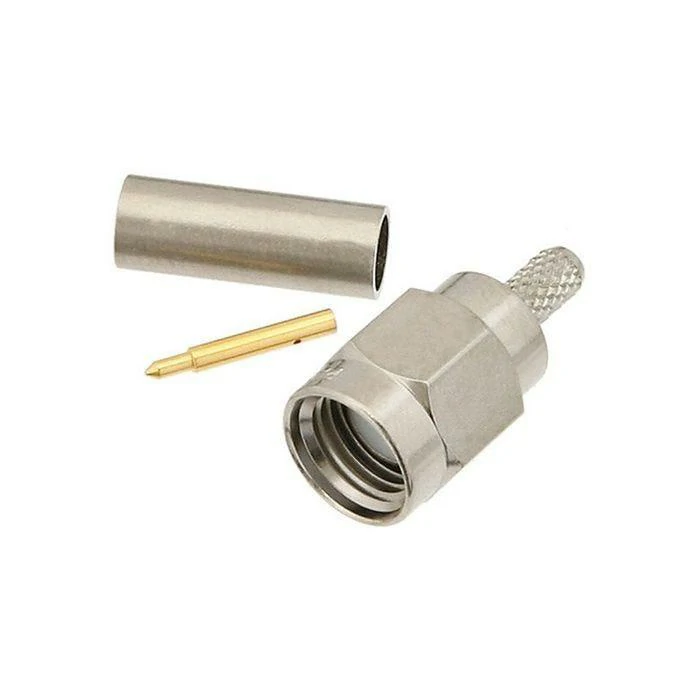
A disassembled crimp-style RF connector showing the connector body, center contact, and ferrule used to terminate a coaxial cable.
When an RF system starts losing range, stability, or measurement accuracy, engineers often check the antenna first. However, the cable between the radio and antenna can quietly become the limiting factor.
Choose Low Loss Coaxial Cable When Signal Margin Becomes Limited
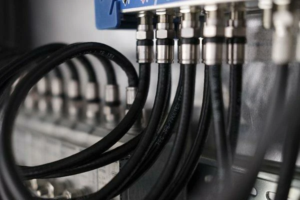
Low loss RF cable assemblies connected to a multiport test system, illustrating organized routing and reliable connector interfaces.
A low loss coaxial cable is not simply a premium version of a regular cable. It is selected when the RF system cannot afford unnecessary attenuation.
In many wireless designs, the available signal margin is smaller than expected.
This becomes especially important in:
- Outdoor antenna installations
- Cellular gateways
- Wi-Fi access points with external antennas
- GPS antenna extension systems
- RF test equipment connections
- Private wireless networks
A few decibels of loss may not appear significant during basic testing. However, near the edge of coverage, those same losses can reduce throughput, increase retransmissions, or create unstable communication.
Engineers usually review cable construction details before selecting a solution. Factors such as conductor size, dielectric material, shielding structure, operating frequency, and cable length all influence the final result.
The RG cable guide is often a useful reference when comparing common coaxial cable families because different RG cables are designed for different mechanical and electrical requirements.
Understand How Cable Loss Affects Antennas, Radios, and RF Modules
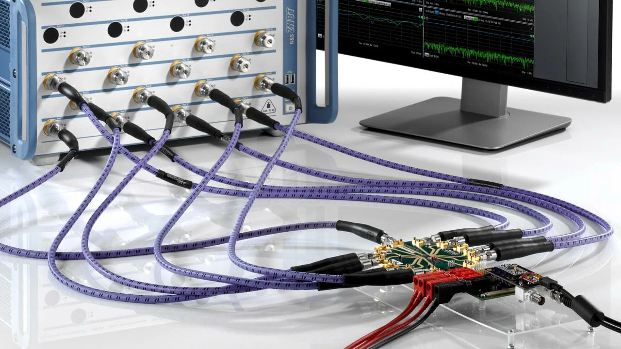
A multiport vector network analyzer setup using RF test cable assemblies to measure several signal paths and S-parameters simultaneously.
In an RF system, the cable is part of the signal path, not just a connection accessory.
Consider a wireless gateway installed inside a building while the antenna is mounted outside.
A typical RF path may include:
| Component | Possible Signal Impact |
| Coaxial cable | Main attenuation over long distances |
| Connector interface | Additional insertion loss |
| Adapter chain | Extra loss and possible reflection |
| Antenna mismatch | Increased return loss |
| Cable installation | Performance variation |
For example, a short SMA cable inside a device may only contribute a small amount of loss. The same cable type used for a several-meter antenna feeder can create a much larger problem.
This is also why professional RF cable assembly suppliers usually consider cable length, connector type, frequency range, and test requirements together instead of selecting the cable separately from the connectors.
Compare Low Loss Cable With Standard RG58 and RG316 Options
Choosing a low loss cable does not mean replacing every existing coaxial cable.
Different cable types solve different engineering problems.
RG58: Flexible and Cost-Effective for Short Connections
RG58 remains popular because it is easy to install, widely available, and compatible with many common RF connectors.
It works well for:
RG316: Small Diameter for Compact RF Designs
RG316 is commonly used where space and flexibility matter more than minimum attenuation.
Typical applications include:
Its smaller diameter allows easier routing, but the trade-off is higher attenuation compared with larger low loss coaxial cables.
The RG316 coaxial cable guide provides more details about its frequency range, construction features, and suitable application scenarios.
Low Loss RF Cable: Designed for Longer and More Demanding Paths
A low loss RF cable becomes the better choice when:
- The cable length increases
- Operating frequency moves higher
- Signal margin becomes limited
- The antenna cannot be placed close to the radio
- RF test accuracy becomes important
A common mistake is choosing cable only by diameter. A larger cable may reduce attenuation, but it must still match the installation requirements.
Before upgrading, engineers should also check:
- Minimum bend radius
- Connector compatibility
- Installation space
- Cable weight
- Environmental conditions
- Required frequency range
The best cable is not always the cable with the lowest published loss. It is the cable that provides enough RF performance without creating mechanical or installation problems.
How Much Cable Loss Can Your RF System Tolerate?
Before selecting a low loss coaxial cable, engineers should understand the actual loss budget.
A cable upgrade only makes sense when the existing cable loss affects system performance.
The calculation normally starts with:
- Transmitter output power
- Receiver sensitivity
- Antenna gain
- Cable length
- Cable attenuation
- Connector quantity
- Adapter quantity
- Required system margin
A system with a short cable and large signal margin may not benefit much from upgrading.
A long cable operating near the frequency limit may require a different approach.
Use a Cable Upgrade Decision Table Before Changing Your RF Cable
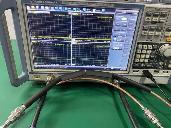
A vector network analyzer is used to measure the insertion loss, return loss, and impedance matching of low loss coaxial cable assemblies.
Replacing an existing coaxial cable is not always the first solution when an RF system has performance issues.
In many cases, engineers discover that the actual limitation comes from a combination of factors:
- Cable length
- Operating frequency
- Connector quality
- Adapter quantity
- Installation environment
- Antenna location
A low loss coaxial cable upgrade can improve the system, but only when the cable is the main source of signal degradation.
For this reason, cable selection should begin with the actual application instead of choosing the lowest attenuation specification available.
Low Loss Cable Upgrade Decision Table
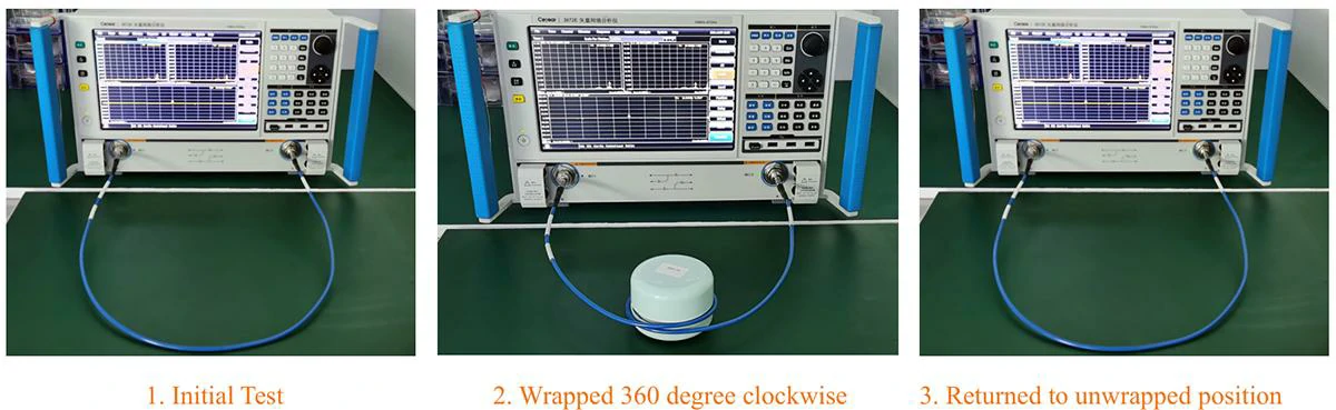
A three-stage VNA test compares coaxial cable performance in its initial position, after a 360-degree bend, and after returning to the original position.
The following table helps engineers decide whether upgrading the cable is necessary.
| Application | Frequency Band | Cable Length | Existing Cable | Common Problem | Recommended Action |
| Indoor Wi-Fi antenna jumper | 2.4 GHz | <1 m | RG316 / RG58 | Minor loss difference | Keep flexible cable |
| Outdoor Wi-Fi antenna feeder | 5 GHz / 6 GHz | 5–15 m | RG58 | High attenuation | Consider low loss RF cable |
| GPS antenna extension | L1/L2 bands | Several meters | Small coax | Weak received signal | Check cable loss first |
| LTE gateway antenna | Sub-6 GHz | Long outdoor route | General coax | Reduced coverage | Upgrade cable type |
| VNA measurement cable | GHz range | Flexible test setup | Standard cable | Unstable measurement | Use tested RF cable assembly |
| Laboratory RF connection | High frequency | Short distance | Mixed adapters | Measurement uncertainty | Reduce adapter chain |
The purpose of this table is not to select one universal cable.
Instead, it helps identify the point where cable loss becomes a system problem.
Choose Cable Based on Loss Risk Instead of Diameter Alone
A common misunderstanding is that a thicker coaxial cable is automatically the best choice.
A larger cable usually provides lower attenuation because it can use a larger conductor and improved dielectric structure. However, RF installation is rarely determined by electrical specifications alone.
A practical cable selection also needs to consider:
Mechanical Space
Large low loss cables may require more room inside equipment cabinets or antenna mounting systems.
A cable that performs well electrically may become difficult to install if the bend radius exceeds the available space.
Connector Compatibility
Not every connector family is available for every cable diameter.
For example, a compact SMA connector may be suitable for a small flexible cable, while a larger feeder cable may require a different connector design.
This is why professional RF projects often select a complete cable solution rather than purchasing cable and connectors separately.
A properly designed RF cable assembly considers the cable, connector interface, length tolerance, and final testing requirement together.
Compare Low Loss Coaxial Cable With Phase Stable Cable
Low loss coaxial cable and phase stable cable are sometimes compared because both are used in demanding RF applications.
However, they solve different engineering problems.
Choosing between them depends on whether the main concern is signal strength or measurement repeatability.
Use Low Loss Cable to Reduce Signal Attenuation
The primary purpose of a low loss coaxial cable is reducing transmission loss.
When a signal travels through coaxial cable, part of the energy is absorbed by conductor resistance and dielectric loss.
The longer the cable and the higher the frequency, the more important this becomes.
Typical situations where low loss cable provides value include:
- Antenna feeder systems
- Wireless communication equipment
- RF modules connected over distance
- Outdoor communication links
- High-frequency signal routing
For example, a 10-meter antenna cable operating near 6 GHz requires a very different approach compared with a short internal jumper operating below 1 GHz.
The cable specification should always match the real working condition.
Use Phase Stable Cable When Measurement Repeatability Matters
A phase stable cable focuses on keeping electrical performance consistent when the cable moves, bends, or experiences temperature changes.
This difference becomes important in:
- VNA testing
- Calibration systems
- Semiconductor testing
- Antenna measurement
- Precision RF laboratories
A standard low loss cable may provide excellent attenuation performance but still experience phase variation after repeated movement.
A phase stable cable is designed to minimize this change.
For engineers working with network analyzers, the cable behavior itself becomes part of the measurement accuracy.
A test cable that changes phase position after bending can introduce uncertainty into S-parameter measurements.
Decide Which RF Problem You Need to Solve First
Before selecting between low loss coaxial cable and phase stable cable, define the actual problem.
| Problem | Better Direction |
| Signal level is too low | Low loss coaxial cable |
| Cable run is too long | Low loss RF cable |
| Measurement changes after moving cable | Phase stable cable |
| VNA calibration is unstable | Phase stable test cable |
| RF path loss affects results | Low insertion loss cable |
| Repeatability is more important than minimum loss | Phase stable solution |
The wrong selection can increase cost without solving the original problem.
A laboratory may not need the lowest attenuation cable if the main issue is phase repeatability.
A wireless installation may not need phase stability if the real limitation is simply excessive feeder loss.
Check Connector Limits Before Choosing a Low Loss Cable
A low loss cable cannot compensate for a poor connection point.
In many RF systems, the connector becomes the weakest part of the transmission path.
A cable may have excellent attenuation specifications, but performance can still decrease because of:
- Incorrect connector installation
- Poor impedance matching
- Damaged contact surfaces
- Loose connections
- Excessive adapter combinations
This is especially important at higher frequencies where small mechanical errors create larger electrical effects.
Match Connector Frequency Rating With Cable Performance
The connector and cable must operate as one system.
For example:
- SMA connectors are widely used for compact RF applications.
- N-type connectors are common in outdoor and higher-power systems.
- TNC connectors provide threaded stability in vibration environments.
- 2.92 mm and 3.5 mm connectors are used in higher-frequency test applications.
Selecting a high-performance cable but using an unsuitable connector can limit the entire RF path.
The final assembly should always be evaluated based on the complete frequency range.
Check Insertion Loss, Return Loss, and VSWR Together
Many engineers focus only on insertion loss when discussing low loss cable.
However, RF performance depends on both transmitted energy and reflected energy.
Insertion Loss
Insertion loss describes how much signal power is lost while passing through the cable assembly.
VSWR
VSWR provides another way to describe impedance matching quality.
A cable assembly with acceptable insertion loss can still have poor VSWR if the interfaces are not properly matched.
Reduce Adapter Chains Before Increasing Cable Performance
Adding adapters is sometimes unavoidable during equipment integration.
However, every additional transition introduces another possible loss point.
A signal path containing:
Radio → adapter → cable → adapter → antenna
may perform worse than:
Radio → customized RF cable assembly → antenna
when the adapter chain becomes excessive.
Reducing unnecessary transitions often improves both reliability and long-term maintenance.
How Do 6 GHz Wireless Systems Change Cable Selection?
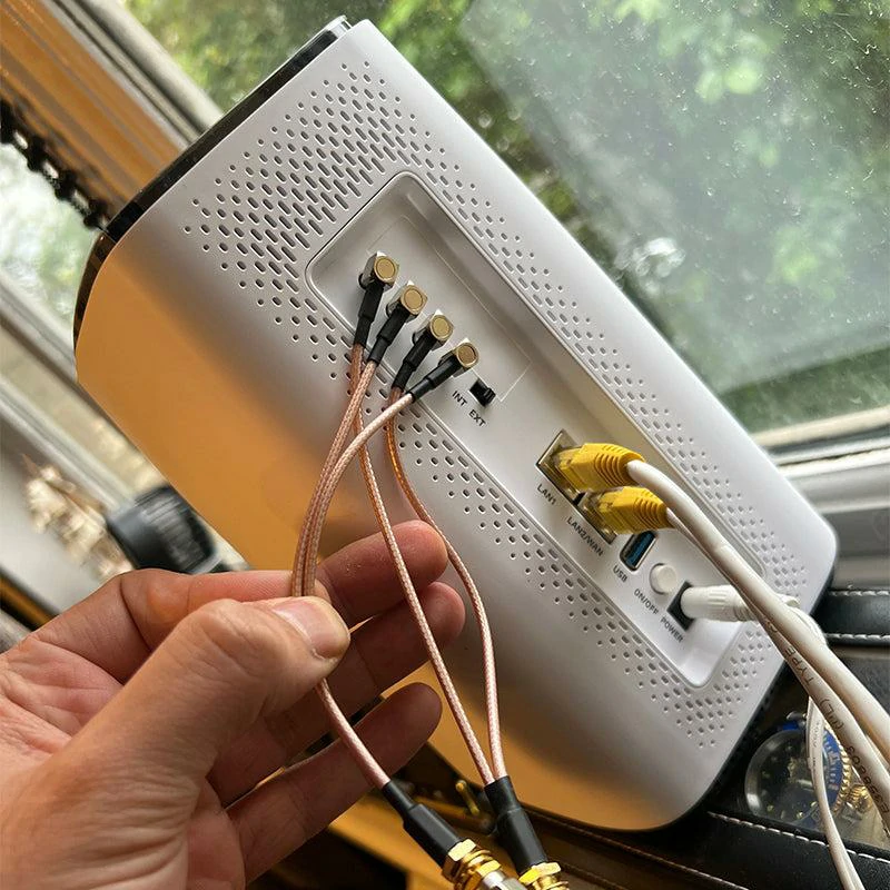
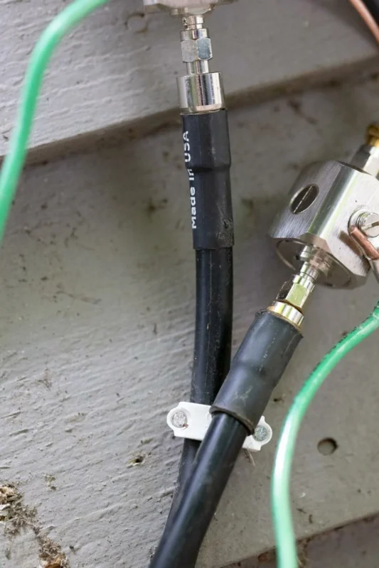
Compact coaxial cable assemblies connected to the antenna ports of a wireless router for cellular or wireless signal transmission.
Wireless technology continues moving toward higher frequency bands.
Wi-Fi 6E, Wi-Fi 7, private wireless networks, and future high-capacity wireless systems all place more attention on RF path quality.
At lower frequencies, a cable with moderate attenuation may still provide enough margin. As frequency increases toward 5 GHz and 6 GHz, the same cable can introduce significantly higher loss.
Treat 5 GHz and 6 GHz as Higher-Loss Planning Zones
Many wireless designs focus on antenna gain and transmitter power but underestimate cable loss.
At 5 GHz and 6 GHz frequencies, small differences in cable attenuation become more important because the available signal margin is often limited.
For example, a short internal cable inside a Wi-Fi access point may not require a premium low loss solution.
However, an external antenna installed several meters away creates a different engineering challenge.
The cable must maintain:
- Low attenuation
- Stable impedance
- Good shielding effectiveness
- Reliable connector performance
- Mechanical durability
A common mistake is using the same cable strategy for both situations.
A compact wireless device and an outdoor antenna feeder may operate in the same frequency range, but their mechanical requirements are completely different.
Keep Cable Runs Short in Compact Wireless Equipment
In many modern wireless products, reducing cable length is often more effective than simply upgrading the cable type.
Shorter RF paths provide several advantages:
- Lower transmission loss
- Fewer connector transitions
- Reduced mechanical stress
- Easier production control
- More consistent RF performance
This is especially important for:
- IoT gateways
- Wireless modules
- Industrial communication equipment
- Embedded antenna systems
For these products, a short flexible cable assembly may provide better overall results than installing a larger low loss cable that creates mechanical problems.
The goal is not to maximize cable specification.
The goal is to achieve reliable RF performance inside the actual product environment.
Test Near the Real Operating Frequency
A cable specification is only useful when it matches the working frequency.
A cable that performs well at 1 GHz may show very different behavior near 6 GHz.
Use Low Loss Coaxial Cable Correctly in VNA Testing
RF measurement systems are particularly sensitive to cable performance.
A test cable is not just a connection between the instrument and the device under test. It becomes part of the measurement system.
When using a VNA, cable characteristics directly influence:
- S-parameter accuracy
- Calibration stability
- Repeatability
- Measurement confidence
Use Low Loss Cable When Test Path Loss Affects Results
A VNA test setup may include several components:
VNA port → cable → adapter → DUT
Every component contributes some electrical effect.
If the cable introduces excessive insertion loss, the measured result may not accurately represent the DUT performance.
This becomes especially important when testing:
- Low-loss filters
- RF amplifiers
- Antennas
- High-frequency connectors
- Microwave components
For these applications, engineers usually select a tested vna test cable with controlled electrical characteristics.
A suitable test cable should provide:
- Stable impedance
- Low insertion loss
- Good return loss
- Reliable connector repeatability
Compare Low Loss Cable With Phase Stable Cable Before Purchasing
A common purchasing mistake is selecting a cable only from the attenuation specification.
For laboratory applications, phase stability may be equally important.
A standard low loss coaxial cable may provide excellent signal transmission, but repeated bending can change electrical phase.
A phase stable cable is designed for applications where the cable position changes during measurement.
Examples include:
- Antenna measurement systems
- VNA calibration environments
- Automated test equipment
- Production RF inspection
The selection depends on the measurement requirement:
| Requirement | Recommended Cable Type |
| Minimum attenuation | Low loss coaxial cable |
| Long RF connection path | Low loss RF cable |
| Frequent cable movement | Phase stable cable |
| Precision measurement | Phase stable test cable |
| General RF connection | Standard coaxial cable |
Save Baseline Measurements After Cable Installation
A new RF cable assembly should be measured before entering regular service.
A useful baseline record includes:
- Cable model
- Cable length
- Connector type
- Frequency range
- Insertion loss curve
- Return loss result
- VSWR measurement
- Test date
Saving this information helps engineers identify future changes caused by:
- Connector wear
- Cable bending damage
- Environmental exposure
- Repeated installation cycles
For professional RF systems, the original test data becomes part of the product history.
Specify RF Cable Assembly Requirements Before Ordering
Many cable problems happen before production begins.
The supplier receives a request such as:
“Need a low loss cable with SMA connectors.”
However, this description does not define enough information for a reliable RF assembly.
A complete specification should include:
- Cable type
- Impedance
- Connector A
- Connector B
- Cable length
- Frequency range
- Maximum insertion loss
- Return loss or VSWR requirement
- Jacket material
- Operating environment
A clearer requirement could be:
50 ohm low loss coaxial cable assembly, SMA male to N male, 3 meters length, DC–6 GHz operation, tested for insertion loss and return loss.
This type of specification reduces communication errors between engineering and manufacturing teams.
Define Connector Orientation and Installation Limits
Connector selection is not only about interface type.
The final assembly should also define:
- Straight or right-angle connector
- Panel mounting requirement
- Cable routing direction
- Minimum bend radius
- Strain relief requirement
- Outdoor protection level
These details affect both installation reliability and production consistency.
A cable that works electrically but cannot be installed correctly will still create field problems.
Validate Low Loss Coaxial Cable Before Deployment
Before installing a large quantity of cable assemblies, incoming inspection helps prevent expensive field failures.
Compare New Cable Performance With the Previous Solution
When replacing an existing cable, the best validation method is comparison.
Engineers can compare:
- RSSI improvement
- S21 measurement
- Signal level
- Network throughput
- Antenna performance
- Test repeatability
This provides real application evidence instead of relying only on catalog specifications.
Document the Final Installed RF Path
The final cable installation should be recorded.
Important information includes:
- Cable part number
- Length
- Connector combination
- Adapter quantity
- Installation route
- Bend radius
- Test results
Good documentation makes future maintenance and repeat purchasing much easier.
FAQ
Is low loss coaxial cable always better than RG58?
No.
Low loss coaxial cable is better when attenuation affects the system budget. For short flexible connections, RG58 may still be the practical choice because of cost and installation convenience.
Can a low loss cable still have poor VSWR?
Yes.
A cable can have low attenuation but poor VSWR because of connector mismatch, installation problems, damaged interfaces, or incorrect components.
