
Many RF cable problems start before the cable is even ordered.
A drawing may only show “SMA cable” or “50 ohm coaxial cable”. For a simple connection, that description may be enough. But once the application moves into higher frequency ranges, longer cable routing, or RF testing equipment, the missing details become important.
The connector interface is only one part of the assembly.
A cable with the same SMA connector can have a different loss value, different flexibility, and different frequency capability depending on the coaxial cable used inside.
This is also why replacing an RF cable is not always a simple “same connector, same length” job.
An engineer checking a failed RF path usually looks at several points:
- Is the cable impedance correct?
- Is the operating frequency within range?
- Is the attenuation acceptable?
- Are the connectors suitable for the cable diameter?
- Was the assembly damaged during installation?
A low loss RF cable is selected when the signal margin is limited and unnecessary transmission loss needs to be reduced.
For RF buyers, the specification written on the purchase order often determines the final result. A clear requirement saves more time than comparing products only by price.
How Do Low Loss RF Cables Improve Signal Transmission?
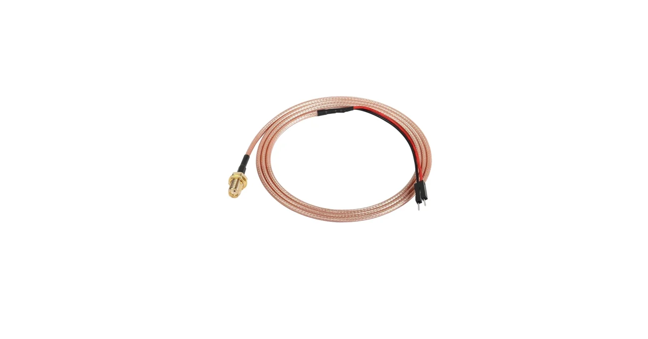
RF signals become weaker as they travel through a coaxial cable.
For short internal connections, the loss difference between cable options may not affect the final equipment performance. However, when the cable length increases, the attenuation accumulates.
This situation appears in many applications:
- antenna connection systems
- wireless communication equipment
- RF measurement setups
- microwave modules
- outdoor communication links
A common purchasing situation is choosing between a flexible cable and a lower loss cable.
Flexible cables are easier to install inside compact equipment.
Low attenuation cables usually provide better transmission characteristics over longer distances.
The choice depends on the actual installation.
For example, an RG316 cable assembly is often selected when space is limited and flexibility is needed. A larger coaxial cable may be considered when lower loss is more important than bending performance.
Neither option replaces the other.
The wrong selection usually happens when the cable is treated as only a mechanical connection.
Check RF attenuation before selecting the cable
Cable loss is usually expressed in dB.
The value changes with frequency and cable length. A cable specification that looks acceptable at a lower frequency may not provide the same result near the upper frequency limit.
| Check Item | Why It Should Be Confirmed |
| Frequency | Determines whether the cable is suitable |
| Length | Directly affects total attenuation |
| Connector type | Influences insertion loss and matching |
| Adapter quantity | Adds extra loss |
| Installation condition | Affects long-term stability |
This is especially important for RF test cables.
A short sample cable may show acceptable results during evaluation. After the production version changes length, connector type, or routing method, the measured result may change.
How Does Low Loss RF Cable Construction Reduce Attenuation?
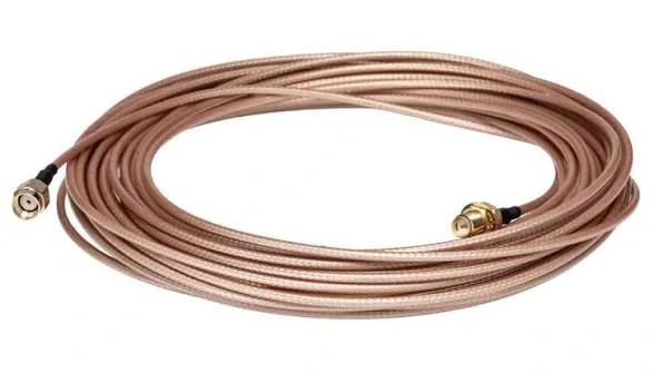
N type RF cable assembly designed for reliable signal transmission. The connector interface, coaxial cable type, and operating frequency should be matched according to application requirements.
The cable structure decides how the RF signal travels.
A coaxial cable is not only a conductor with a protective cover. Inside the cable, each layer has a specific function.
The center conductor carries the signal.
The dielectric maintains the electrical distance between the conductor and shielding.
The shielding layer helps control external interference.
During sourcing, engineers normally check more than the cable name.
| Cable Section | Selection Point |
| Center conductor | Material and conductor size |
| Dielectric | Electrical characteristics |
| Shielding | Interference protection |
| Jacket | Mechanical protection |
A cable with better shielding is not automatically a lower loss cable.
These two specifications solve different problems.
Lower attenuation mainly relates to how efficiently the signal travels through the cable. Shielding focuses more on preventing interference from entering or leaving the signal path.
This difference is sometimes missed during product selection.
For production orders, the cable request should contain enough information for the supplier to match the complete assembly.
A practical RF cable specification normally includes:
- 50Ω impedance
- working frequency
- cable model
- cable length
- connector combination
- termination method
- inspection requirement
For example:
50Ω SMA cable assembly, RG316 coaxial cable, specified length, operating frequency requirement, VSWR inspection required.
This description is much clearer than simply writing “low loss cable”.
The cable, connector, and application need to be considered together. A suitable RF assembly starts with correct information before production begins.
How Do You Calculate RF Cable Attenuation Before Selection?
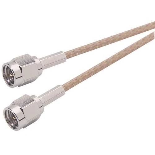
Low loss coaxial RF cables help reduce signal attenuation in longer transmission paths. Frequency range, cable structure, impedance, and connector type should be considered before selection.
A cable specification sheet usually provides attenuation data, but many purchasing mistakes happen because the value is read without considering the complete signal path.
For example, a cable may show a low loss value at 1 GHz. That does not mean the same cable will maintain the same loss at 6 GHz or 18 GHz.
The operating frequency changes the result.
Cable length changes the result.
Even the number of connectors in the assembly changes the final measurement.
This is why RF engineers normally calculate the expected loss before confirming a cable design.
A simple cable calculation starts with attenuation per meter.
This calculation only covers the cable itself.
The complete assembly may include:
- SMA connectors
- N-type connectors
- adapters
- panel interfaces
- additional connection points
Each part can introduce additional insertion loss.
RF Attenuation Calculation Table
| Parameter | Example Value | Purpose |
| Cable Model | Low Loss RF Cable | Identify cable construction |
| Frequency | 6 GHz | Confirm operating range |
| Length | 2 m | Calculate cable loss |
| Attenuation | dB/m | Estimate signal reduction |
| Connector Count | 4 pcs | Add connection loss |
| Total Loss | dB | Check final RF margin |
This type of calculation is especially useful before making custom cable assemblies.
A common production issue is that the sample and mass production cable use different lengths or different cable models.
The sample passes testing.
The production batch shows different insertion loss.
The problem is not always the connector. The cable specification may have changed.
How Does Cable Length Affect Low Loss RF Cable Performance?
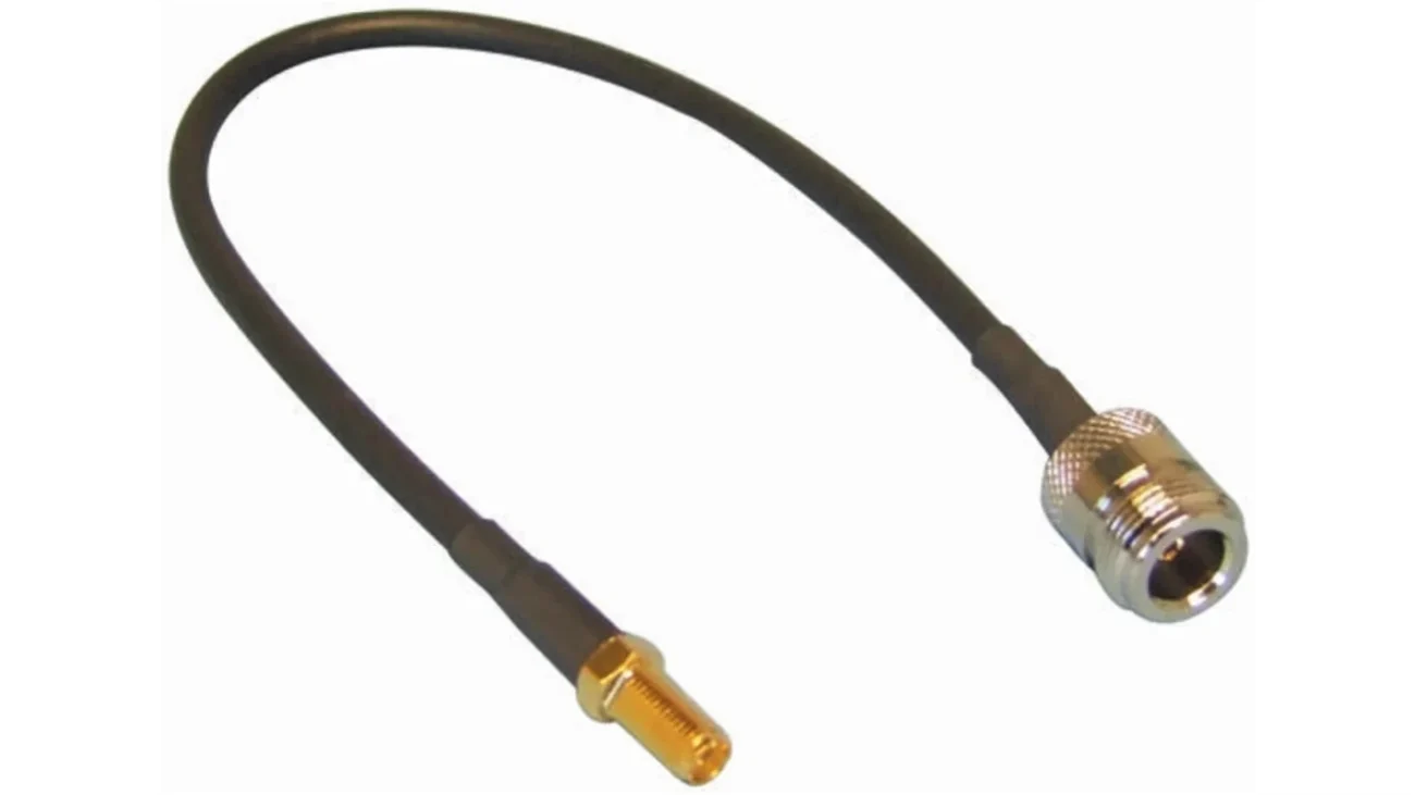
Cable length is often treated as a mechanical requirement.
In RF applications, it is also an electrical parameter.
A 20 cm cable and a 2 m cable may use the same connector combination, but their transmission performance will not be identical.
Longer cable means:
- more conductor loss
- more dielectric loss
- higher total attenuation
This does not mean every system should use the shortest possible cable.
A cable that is too short may create installation problems:
- excessive bending near the connector
- mechanical stress on solder joints
- difficulty routing inside equipment
The practical solution is usually finding a suitable balance between electrical loss and mechanical installation.
For example, an antenna cable installed inside a device may require flexibility because the routing path is limited.
A laboratory test cable may accept a larger cable diameter because measurement stability is more important than installation space.
Different applications require different priorities.
How Do Frequency and Impedance Affect Low Loss RF Cable Selection?
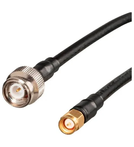
N type to SMA low loss RF cable assembly designed for RF signal connection applications. Connector type, impedance, cable loss, and frequency capability should be confirmed before production.
Frequency is one of the first specifications to confirm.
A low loss RF cable suitable for a lower frequency application may not be the right option for microwave systems.
When checking cable suitability, engineers usually review:
- frequency range
- attenuation curve
- VSWR
- impedance
- connector frequency rating
A cable assembly is a complete RF path.
The cable, connector, and equipment port should work within the same electrical system.
Match 50Ω Cables With RF Systems
Most RF communication and test systems use 50Ω impedance.
Two connectors may physically connect together, but the electrical specification still needs to match.
For example, a 50Ω SMA cable assembly should normally connect with 50Ω RF equipment ports.
The connector appearance alone does not confirm compatibility.
50Ω Low Loss RF Cable Matching Checklist
| Component | Confirm Before Ordering |
| Cable | 50Ω impedance |
| Connector | Matching RF interface |
| Equipment Port | Correct impedance |
| Adapter | Suitable frequency range |
| Antenna | Compatible RF specification |
How Are Low Loss RF Cables Used in Microwave and Antenna Systems?
Higher-frequency applications usually leave less room for cable selection mistakes.
In microwave systems, a small increase in loss can affect the available signal margin.
Typical applications include:
- microwave test systems
- radar equipment
- wireless communication devices
- antenna connection systems
At these frequencies, the cable assembly should be considered together with the connector.
A cable may have suitable attenuation characteristics, but an unsuitable connector termination can still create problems.
Select Cable Assemblies for Antenna Connections
Antenna systems often use coaxial cable assemblies because the cable needs to transfer RF signals between the antenna and equipment.
Common requirements include:
- stable impedance
- suitable frequency range
- reasonable cable loss
- mechanical durability
For example, an SMA antenna cable used in a wireless device may require a different cable structure compared with an outdoor antenna feeder.
The indoor cable may prioritize flexibility.
The outdoor cable may require stronger mechanical protection.
The application environment changes the selection.
How Do RF Connectors Influence Low Loss Cable Performance?
The connector is the visible part of an RF cable assembly, but it is not the only performance factor.
A connector must match the cable size, termination method, and operating frequency.
For example, an SMA connector designed for RG316 cable is not automatically suitable for a larger RG58 cable.
The rear section of the connector is different.
The ferrule size is different.
The termination process is different.
A correct connection starts from the cable side, not only the mating interface.
Check Connector Loss During RF Assembly Selection
Connector-related problems may come from:
- poor termination
- incorrect cable matching
- damaged center pin
- improper assembly process
Visual inspection can find some mechanical issues.
It cannot confirm complete RF performance.
For production cable assemblies, engineers may use:
- VSWR testing
- insertion loss testing
- return loss measurement
- continuity checking
A continuity test only confirms that the electrical path is connected.
It does not prove that the RF characteristics meet the requirement.
How Should Engineers Select Low Loss RF Cables for Custom Projects?
A custom RF cable order usually starts with a simple request.
“Need SMA cable, 500 mm length.”
For a mechanical drawing, this may look complete.
For cable production, it is only the beginning.
The same SMA interface can be assembled with different coaxial cables. RG316, RG174, RG58, and other cable families have different outside diameters, attenuation values, and bending characteristics.
The cable choice affects the finished assembly.
During project communication, engineers normally confirm the details step by step instead of selecting only from a connector picture.
A supplier may need to check:
- cable size
- connector structure
- frequency requirement
- impedance
- assembly method
A small mismatch at this stage can create problems later.
For example, a connector that fits the equipment port may not match the cable used for production. The assembly may look correct but require a different crimp tool, different soldering process, or different inspection method.
This is why RF cable selection should be considered as an assembly process, not only a component purchase.
What Details Should Be Confirmed Before RF Cable Production?
A production drawing should describe the electrical and mechanical requirements together.
A typical RF cable specification may include:
| Item | Example |
| Cable | Low loss coaxial cable |
| Impedance | 50Ω |
| Frequency | Required operating band |
| Length | Finished cable length |
| Connector | SMA / N / BNC |
| Testing | VSWR or insertion loss |
The purpose of these details is not to make the document complicated.
They help both sides understand the same product.
This becomes more important when the order moves from sample stage to batch production.
A sample cable may be approved after bench testing.
Later, production cables may use a different cable batch, different assembly operator, or different process condition. Without clear specifications, it becomes difficult to identify where the difference comes from.
How Does the Application Change the Cable Choice?
The same RF cable may behave differently in different environments.
Inside a compact electronic device, the cable route may contain several bends. A flexible coaxial cable may be preferred because installation space is limited.
A measurement setup is different.
The engineer may focus more on repeatability and RF stability. Cable movement, connector quality, and phase change may receive more attention.
Outdoor equipment creates another set of requirements.
The cable may experience:
- temperature variation
- mechanical pulling force
- long-term exposure
The selection is not only about lower attenuation.
The assembly must also survive the environment where it will be used.
How Should Low Loss RF Cables Be Tested Before Delivery?
RF cable inspection usually includes two different parts.
The first part is physical checking.
The second part is electrical verification.
A connector can be installed correctly and the cable can pass a continuity test. However, this does not confirm the RF performance.
For higher-frequency applications, additional measurement is often required.
Which Measurements Are Used for RF Cable Assemblies?
Different projects require different inspection levels.
A basic production check may include:
| Test | Purpose |
| Continuity | Check electrical connection |
| Appearance | Check assembly condition |
| VSWR | Check matching condition |
| Insertion Loss | Check transmission loss |
For test cables and microwave applications, engineers usually pay more attention to VSWR and insertion loss.
A continuity tester only checks whether the circuit is connected.
It cannot show whether the signal path has excessive reflection.
That difference matters when the cable operates near the upper frequency range.
What Problems Can Appear During Cable Assembly Inspection?
Some RF issues are not visible from the outside.
Examples include:
- center pin alignment problems
- poor termination
- cable damage near the connector
- incorrect connector and cable matching
A finished assembly may pass visual inspection but still require RF measurement.
This is especially true for small connectors and high-frequency cable assemblies.
During production, consistent inspection methods are more useful than checking only the first few pieces.
Low Loss RF Cable Acceptance Checklist
| Check Point | Confirmation |
| Cable model | Match approved specification |
| Impedance | Confirm 50Ω system |
| Frequency | Within application range |
| Length | Match drawing |
| Connector | Correct interface |
| RF test | Complete when required |
| Appearance | No assembly damage |
FAQ
A customer wants to replace an existing RF cable. Can the connector stay the same?
The connector interface can sometimes remain unchanged, but the cable behind the connector still needs checking.
Different cable sizes may require different connector bodies or termination methods.
Is a cable with a higher frequency rating always better?
Not necessarily.
The actual application frequency, cable loss, connector matching, and testing requirement should be considered together.
What information helps suppliers quote a custom RF cable quickly?
The most useful information is the cable type, connector combination, finished length, frequency requirement, impedance, and quantity.
A drawing or sample can also help confirm the assembly structure.
When should RF cable assemblies be tested with a VNA?
VNA testing is commonly considered for applications where return loss, VSWR, or insertion loss needs verification.
The required test depends on the system sensitivity and operating frequency.
Final Practical Note
Selecting a low loss RF cable is not only a matter of finding a cable with a lower attenuation number.
The complete assembly needs to fit the actual system.
Before production starts, engineers and suppliers should have the same understanding of the cable structure, connector interface, working frequency, and inspection method.
A clear specification at the beginning usually prevents repeated changes after samples are tested or products enter production.
