
A cable assembly can pass continuity and still be the wrong RF part.
This happens more often than many buyers expect. The connector mates correctly, the cable diameter looks similar, and the first sample works during a basic bench test. The problem appears later when the assembly is installed into the final system, routed through a tighter space, exposed to vibration, or operated near the upper frequency limit.
A coaxial cable assembly is not only a cable with two connectors attached. The cable type, connector interface, termination method, impedance control, and inspection process all affect the final RF result. A mismatch in any one of these areas can increase insertion loss, change VSWR, or create inconsistent performance between production batches.
This guide explains how to evaluate coaxial cable assemblies from an engineering and procurement perspective, including cable selection, connector matching, loss estimation, testing requirements, and custom assembly considerations.
How Does a Coaxial Cable Assembly Build a Complete RF Connection?
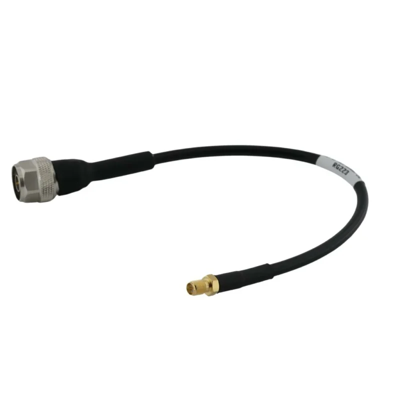
Many sourcing problems begin with an incomplete definition of the product.
A request such as “Need an RF cable” or “Need SMA cable” usually describes only the visible interface. It does not define the electrical and mechanical requirements that determine whether the assembly will work correctly.
A complete coaxial cable assembly normally includes:
- Coaxial cable
- Connector A
- Connector B
- Cable termination process
- Mechanical protection
- Electrical testing
The final product is a complete transmission path, not a combination of independent components.
For example, an SMA male connector designed for a thin cable such as RG316 is not automatically suitable for RG58 or RG142 cable. The front interface may look identical, but the rear body, ferrule size, center pin design, and termination method are different.
This is a common procurement mistake:
The connector fits mechanically, so the buyer assumes the assembly is interchangeable.
In RF systems, mechanical compatibility is only the first check.
Electrical compatibility requires confirmation of:
- Impedance
- Frequency range
- Cable attenuation
- Connector rating
- Assembly quality
- Application environment
A cable assembly used for a short internal connection inside a device may have completely different requirements from a test cable used with a vector network analyzer.
Understand Why a Cable Assembly Is More Than Just a Coax Cable
A coaxial cable itself provides the transmission medium. However, the assembly process determines whether the cable can maintain its intended electrical characteristics.
Common methods include:
- Crimp termination
- Solder termination
- Clamp termination
The correct method depends on cable construction, connector design, and application requirements.
Cable construction affects assembly selection
The coaxial cable inside the assembly determines many practical limits.
Important cable characteristics include:
| Parameter | Why It Matters |
| Conductor size | Affects signal transmission and DC resistance |
| Dielectric material | Influences impedance and frequency capability |
| Shielding structure | Determines interference protection |
| Outer diameter | Affects connector matching and installation space |
| Flexibility | Determines routing and bending capability |
| Attenuation | Determines signal loss over distance |
A small diameter cable may be easier to install, but it usually has higher attenuation compared with larger low-loss cables.
A larger cable may provide better RF performance but require more installation space and a different connector design.
Identify the Role of Cable Assemblies in RF Systems
Coaxial cable assemblies are used wherever RF signals need to move between two points while maintaining controlled impedance.
Typical applications include:
- Antenna systems
- Wireless communication equipment
- RF testing instruments
- Microwave modules
- Navigation systems
- Industrial communication equipment
Every connection point in this path should be considered.
For example:
- A high-frequency connector cannot compensate for a cable with excessive loss.
- A low-loss cable cannot solve an impedance mismatch caused by the wrong connector.
- A good connector cannot fix poor termination quality.
The assembly must be evaluated as one complete RF component.
Match Cable Assemblies With the Complete RF Signal Path
Before selecting an assembly, engineers and buyers should define the entire connection requirement.
A practical specification should include:
| Requirement | Example |
| Connector A | SMA Male |
| Connector B | N Female |
| Cable Type | RG316 / RG58 / LMR series |
| Impedance | 50Ω |
| Length | 1 m |
| Frequency Range | DC–6 GHz |
| Application | Antenna / RF Test / Communication |
This information prevents incorrect substitutions during purchasing.
For example, replacing an RG58 assembly with a thinner RG316 assembly may solve a space problem, but it will also change attenuation characteristics. Likewise, replacing a standard SMA assembly with a higher-frequency connector does not automatically improve the complete system.
The limiting factor may still be the cable.
How Do You Choose the Right Coaxial Cable Assembly for an RF Application?
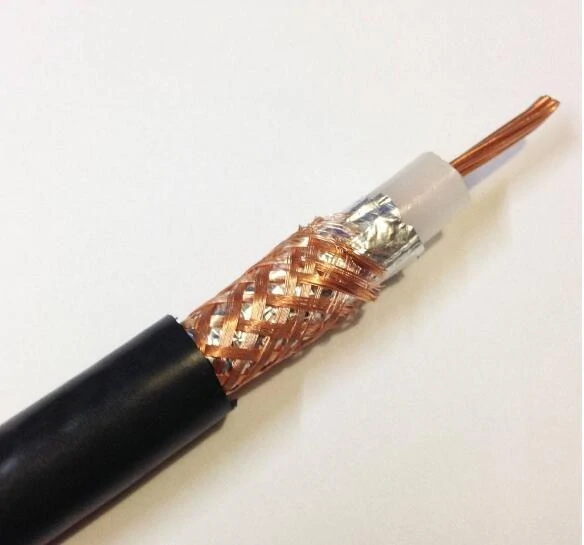
Cross-section view of a coaxial cable showing the inner conductor, dielectric insulation, braided shielding layer, and outer jacket used for RF signal transmission.
Selecting a coaxial cable assembly starts with the operating environment, not the connector name.
Two assemblies may use the same connector interface but serve completely different purposes.
A short SMA-to-SMA jumper inside a test fixture has different requirements from a 5-meter outdoor antenna cable.
Common selection factors include:
Frequency requirement
The cable assembly should have enough frequency margin above the working frequency.
A cable assembly operating close to its maximum rated frequency may show greater sensitivity to:
- Connector quality
- Cable bending
- Assembly variation
Cable attenuation
For long-distance transmission, attenuation often becomes the main limitation.
A buyer should not only ask:
“Can this cable work at 6 GHz?”
The more useful question is:
“How much loss will this 2-meter assembly introduce at 6 GHz?”
The answer depends on:
- Cable model
- Cable length
- Connector quantity
- Termination quality
Installation requirements
Mechanical requirements often conflict with electrical performance.
| Application Requirement | Typical Consideration |
| Tight installation space | Small diameter flexible cable |
| Long distance | Low attenuation cable |
| Repeated movement | Flexible cable with suitable bend radius |
| Laboratory measurement | Precision assembly |
| Outdoor installation | Weather-resistant construction |
A cable that performs well electrically may not be suitable mechanically.
For example, a low-loss semi-rigid cable can provide excellent RF characteristics but may fail in an application requiring repeated bending.
How Do Cable Type and Connector Choice Affect Assembly Performance?
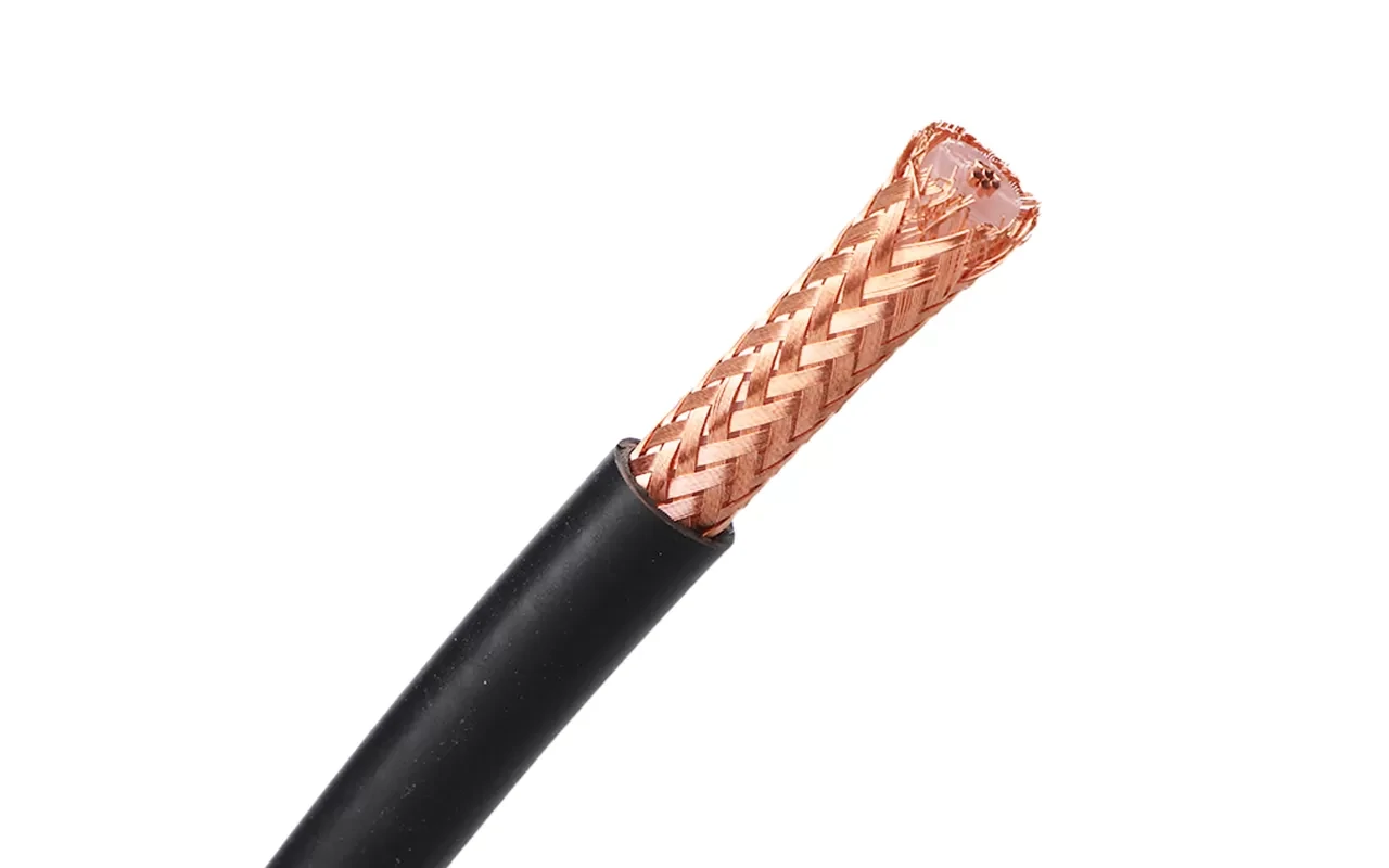
Close-up view of the braided copper shielding layer inside a coaxial cable, helping reduce electromagnetic interference and maintain RF signal integrity.
A connector can look correct and still create problems after the cable assembly enters production.
This is something suppliers often see when customers replace an existing RF cable assembly. The interface is usually the first thing people check:
“Is it SMA?”
“Is it N type?”
“Does it connect to the equipment?”
If the answer is yes, the assembly appears acceptable.
However, the connector interface is only the front end of the assembly. The rear structure must match the cable that it is installed on. A connector designed for RG316 is not automatically suitable for RG58, even though both may use an SMA interface.
The difference is inside the connector:
- Center pin diameter
- Cable dielectric size
- Braid position
- Ferrule dimensions
- Termination method
These details determine whether the assembly maintains stable RF performance after production.
A sample may pass a simple continuity check and still fail later during:
- VNA testing
- vibration testing
- repeated mating cycles
- high-frequency operation
This is why experienced buyers specify the complete assembly, not only the connector name.
Match the Connector Body With the Cable Before Ordering
One of the most common purchasing mistakes is selecting connectors separately from cable specifications.
An SMA connector for RG316 and an SMA connector for RG58 are mechanically different products.
The front mating interface may be identical, but the cable side is not.
A practical RF cable assembly specification should look closer to this:
| Item | Example Requirement |
| Connector A | SMA Male |
| Connector B | N Female |
| Cable | RG316 50Ω |
| Length | 1 m |
| Frequency | DC–6 GHz |
| Termination | Crimp / solder |
| Test Requirement | VSWR + insertion loss |
This type of description reduces supplier interpretation errors and improves repeat production consistency.
Compare Cable Families Before Building the Assembly
The cable inside the assembly usually determines the final limitation.
Many buyers focus on connector frequency ratings because the specification is easy to read. A connector may be rated for 18 GHz, but if the selected cable has high attenuation or poor mechanical compatibility, the complete assembly may not achieve the expected result.
Some common cable choices:
| Cable Family | Practical Advantage | Typical Limitation |
| RG316 | Small diameter, easy routing in compact equipment | Higher loss at longer lengths |
| RG58 | Cost-effective general RF cable | Not ideal for long high-frequency links |
| RG142 | Better temperature resistance and stability | Larger diameter, less flexible |
| LMR series | Lower attenuation for longer runs | Requires more installation space |
| Semi-flex cable | Stable microwave performance | Limited repeated bending |
There is no universal replacement between cable families.
A thinner cable may solve an installation problem but increase insertion loss.
A low-loss cable may improve RF performance but create problems inside a small enclosure.
The final choice depends on what the assembly needs to do after installation.
How Does Connector Selection Influence RF Reliability?
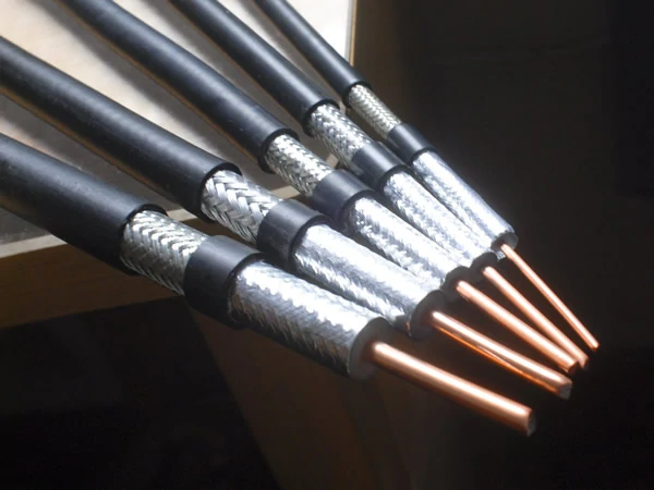
Multiple coaxial cable designs showing different conductor sizes, shielding structures, and cable constructions for RF applications.
The connector is not only a mechanical interface.
Inside an RF cable assembly, the connector affects:
- signal transition
- impedance continuity
- return loss
- insertion loss
- mechanical stability
At lower frequencies, some assembly problems may remain unnoticed.
At higher frequencies, small dimensional differences become more visible.
For example, poor center pin alignment or inconsistent termination can create impedance discontinuity near the connector transition area.
This is one reason why RF manufacturers normally perform electrical testing after assembly rather than relying only on incoming component inspection.
Consider Connector Type According to the Application
Different connector families solve different connection problems.
SMA cable assemblies
SMA is widely used in:
- RF modules
- wireless devices
- laboratory equipment
- antenna connections
The compact size makes SMA suitable where installation space is limited.
However, buyers should confirm:
- standard SMA or reverse polarity SMA
- male/female interface
- cable compatibility
- operating frequency
A visually similar connector may not be electrically interchangeable.
N Type cable assemblies
N type assemblies are often used where mechanical strength is important.
Common applications include:
- outdoor antennas
- communication systems
- base station connections
Compared with smaller connectors, N type provides a more robust threaded connection.
For outdoor applications, buyers should also consider:
- waterproof structure
- sealing method
- cable jacket material
- environmental exposure
The connector itself is only one part of the outdoor reliability equation.
BNC cable assemblies
BNC remains common in test and measurement environments because it allows fast connection.
However, one detail is often overlooked:
50Ω BNC and 75Ω BNC are different.
They may physically connect, but they are intended for different systems.
For RF applications, impedance should always be confirmed before substitution.
Which Cable Assembly Details Should Be Confirmed Before Production?
Before placing a production order, buyers should confirm more than the connector names.
A complete RF cable assembly requirement normally includes:
| Specification | Why It Matters |
| Cable model | Determines loss and mechanical characteristics |
| Connector gender | Prevents interface mismatch |
| Polarity | Avoids SMA/RP-SMA mistakes |
| Length tolerance | Affects installation and RF loss |
| Impedance | Maintains system matching |
| Frequency range | Confirms application suitability |
| Test requirement | Defines acceptance criteria |
This information is especially important for OEM projects.
A cable assembly may be acceptable for a prototype but create problems when production volume increases.
Common production issues include:
- cable length variation
- inconsistent crimping
- connector damage during assembly
- missing test records
- mixed cable specifications
For repeat orders, keeping the assembly specification documented is often more valuable than simply keeping the product name.
How Does Cable Length Change RF Assembly Performance?
Cable length is often underestimated during purchasing.
A 20 cm cable and a 3 m cable using the same connector combination are not the same RF product.
The longer assembly introduces additional:
- attenuation
- phase change
- mechanical loading
- installation difficulty
For low-frequency applications, the difference may be acceptable.
For microwave systems, even small changes can affect measurement accuracy.
A useful calculation method is:
Total Assembly Loss = Cable Loss + Connector Loss
Where:
- Cable Loss = Length × Attenuation per meter
- Connector Loss = Total loss from installed connectors
Example:
A 3 m cable assembly:
- Cable attenuation: 0.3 dB/m
- Two connectors: 0.2 dB total
Estimated loss:
3 × 0.3 + 0.2 = 1.1 dB
This calculation helps compare options before testing.
It does not replace measurement, because actual results are also affected by:
- termination quality
- cable bending
- connector condition
- production consistency
Coaxial Cable Assembly Selection Decision Matrix
When evaluating an assembly, buyers can use the following quick decision guide:
| Application Condition | Recommended Direction | Main Reason |
| Short internal connection | Flexible small cable | Easier installation |
| Long antenna feeder | Low-loss cable assembly | Reduce attenuation |
| High-frequency measurement | Precision assembly | Control VSWR and loss |
| Outdoor communication | Weather-resistant assembly | Environmental protection |
| Repeated production | Documented custom assembly | Maintain consistency |
| Limited installation space | Small diameter cable | Mechanical fit |
This type of evaluation prevents selecting an assembly only by connector appearance.
How Are Coaxial Cable Assemblies Verified Before Shipment?
A cable assembly can look perfect on the outside and still create problems after installation.
This is why RF assembly inspection cannot stop at connector appearance or continuity checking.
Continuity only confirms that the electrical path is connected. It does not show whether the assembly maintains stable RF characteristics at the working frequency.
For production cable assemblies, the inspection process usually covers two areas:
- Mechanical quality
- Electrical performance
Mechanical inspection confirms the assembly was built correctly. RF testing confirms whether it performs as expected.
Check Mechanical Details Before RF Testing
Before connecting the assembly to test equipment, manufacturers normally verify basic production details:
| Inspection Item | Purpose |
| Connector model | Confirm correct interface |
| Cable type | Prevent material substitution |
| Length | Match installation requirement |
| Termination condition | Check crimp/solder quality |
| Label information | Support traceability |
Some problems are difficult to find after installation.
For example, a weak braid connection may pass a basic continuity test but become unstable after repeated bending or vibration.
For OEM applications, keeping assembly records is also important. A cable ordered six months later should match the original specification, not only the appearance.
Measure RF Performance Instead of Guessing
For RF applications, electrical testing is usually required.
Common tests include:
- VSWR
- Insertion loss
- Return loss
- Continuity
- Insulation resistance
A Vector Network Analyzer (VNA) is commonly used when the application requires accurate RF measurement.
When Should You Specify a Custom Coaxial Cable Assembly?
Standard cable assemblies cover many common requirements.
However, production equipment and communication systems often have their own limitations:
- special connector combinations
- fixed installation space
- unusual cable length
- environmental requirements
In these cases, a custom coaxial cable assembly is usually more practical.
Define the Complete Requirement Before Production
A custom assembly request should include more than:
“SMA cable”
A supplier normally needs:
- Connector A and B
- Cable model
- Length
- Impedance
- Frequency range
- Quantity
- Testing requirement
For example:
50Ω coaxial cable assembly, N male to SMA female, RG316 cable, 1 m length, DC–6 GHz application, require VSWR inspection before shipment.
This type of specification reduces communication errors between engineering, purchasing, and production teams.
Custom Assembly Helps Maintain Repeatability
For prototype testing, one working sample may be enough.
For mass production, repeatability becomes the priority.
How Should Buyers Prepare a Coaxial Cable Assembly Request?
Many RF sourcing problems start with incomplete information.
A request like:
Need RF cable
does not provide enough details for accurate production.
A practical RF cable assembly request should include:
| Required Information | Example |
| Connector | SMA Male to N Female |
| Cable | RG316 |
| Impedance | 50Ω |
| Length | 500 mm |
| Frequency | DC–6 GHz |
| Application | Antenna / Test Equipment |
| Quantity | 100 pcs |
This information helps suppliers recommend a suitable assembly instead of making assumptions.
FAQ
Can different connectors be used on each side of a coaxial cable assembly?
Yes. Many assemblies use different interfaces, such as N male to SMA female.
Does cable length affect RF performance?
Yes. Longer cable assemblies generally introduce more attenuation.
Why does a new RF cable assembly need testing if the cable and connectors are correct?
Because the parts being correct does not always mean the finished assembly will perform correctly. Problems can come from the connector installation, cable termination, or impedance transition area. A cable assembly may look normal and pass a basic connection check, but RF tests can show different results at the working frequency.
Why can the same coaxial cable assembly perform differently after production?
A prototype and a production batch are not always identical if the assembly details are not fixed. Changes in cable source, connector batch, or termination process may affect the result. For projects requiring repeated supply, it is better to keep the approved cable model, connector specification, and test method as part of the product record.
What should I send to a supplier when requesting a custom coaxial cable assembly?
A product photo or connector name is usually not enough. A useful request should include both connector ends, cable type, length, impedance, operating frequency, quantity, and any test requirements. If the assembly is part of an existing device, a drawing or sample can help reduce misunderstanding.
