
A cable assembly can pass continuity testing and still create problems in an RF system.
This happens more often than many buyers expect. The connector mates correctly, the cable length looks right, and the first prototype performs normally on the bench. The issue appears later when the assembly is installed inside equipment, bent around a limited space, exposed to vibration, or tested near the upper frequency limit.
A coax cable assembly is not only a cable with two connectors attached. The cable structure, connector interface, termination process, and inspection method all affect the final RF path. A mismatch between these elements can increase insertion loss, raise VSWR, or create inconsistent results between prototype samples and production batches.
For engineers and purchasing teams, the key question is not simply “Can this cable connect?” The more practical question is “Will this assembly maintain the expected RF characteristics after installation and repeated production?”
Why Are Coax Cable Assemblies Used in RF Systems?
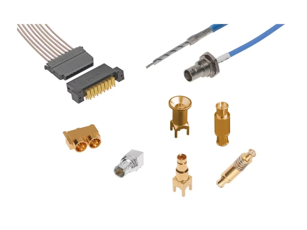
Various RF connectors and cable assembly components used for customized coaxial cable solutions. Connector selection, cable type, termination method, and frequency requirements determine the final RF performance.
In an RF system, the cable assembly acts as the connection between two points that need controlled signal transmission. Instead of installing raw coaxial cable and attaching connectors during equipment assembly, many manufacturers use pre-terminated assemblies supplied with defined dimensions and tested performance.
A typical coax cable assembly contains four main elements:
| Component | Function |
| Coaxial Cable | Transfers RF signals while maintaining impedance |
| RF Connector | Provides mechanical and electrical interface |
| Termination Process | Creates the connection between cable and connector |
| Testing | Confirms electrical and mechanical requirements |
The cable itself determines many basic characteristics, including attenuation, flexibility, shielding effectiveness, and frequency capability. A small flexible cable such as RG316 may fit compact equipment designs, while a larger cable such as RG142 or LMR series may be selected when lower loss is required.
The connector choice is equally important. An SMA connector designed for RG316 cannot automatically replace an SMA connector designed for RG58, even though both share the same external interface. The rear body, ferrule size, center contact, and assembly method must match the cable construction.
This is a common sourcing mistake. Buyers sometimes compare only the front connector interface because it is the visible part of the assembly. In RF production, the hidden section behind the connector often determines whether the assembly remains stable.
Identify where cable assemblies replace separate cable installation
Using finished cable assemblies provides several practical advantages in manufacturing:
- Reduced assembly work during equipment production
- Consistent connector termination quality
- Repeatable cable length and routing
- Easier incoming inspection
- Lower risk of incorrect connector installation
For production environments, repeatability matters more than a single successful prototype. A manually assembled cable may work during testing but produce variation when multiple operators repeat the same process.
A factory-produced RF cable assembly normally controls details such as stripping dimensions, crimp force, soldering temperature, connector torque, and final electrical inspection. These details are difficult to maintain when assembly work is distributed across different production locations.
Connect cable assemblies with complete RF transmission paths
A coax assembly is only one part of the entire RF path.
Every transition point can introduce a small amount of loss or mismatch. The cable may have excellent specifications, but an unsuitable connector transition or poor termination can reduce the performance of the complete path.
For this reason, RF engineers usually evaluate the assembly as a system rather than checking individual parts separately.
How Do You Select the Right Coax Cable Assembly?
Selecting a cable assembly starts with the operating requirements, not the connector drawing.
Many RF purchasing problems come from specifying only the connector type and cable length while leaving out frequency, impedance, and testing requirements.
A practical RF request should include:
- Cable model
- Connector type on both ends
- Connector orientation
- Cable length
- Operating frequency
- Impedance
- Required inspection items
Match cable type with operating frequency
Different coaxial cables have different attenuation characteristics and mechanical behavior.
A shorter cable run inside a wireless module may prioritize flexibility and compact size. A longer connection between an antenna and communication equipment may require a lower-loss cable.
| Cable Type | Typical Application Consideration |
| RG316 | Small equipment, flexible internal wiring |
| RG178 | Compact RF modules requiring very small diameter |
| RG405 | Semi-rigid applications with stable routing |
| LMR Series | Longer RF links requiring lower attenuation |
The highest frequency rating of the cable alone does not define the complete assembly capability. Connector design, termination quality, and installation conditions also affect the final result.
A cable assembly used near its frequency limit requires more attention to connector matching and test verification.
Coax Cable Assembly Selection Checklist
Before sending an RF cable assembly request to a supplier, confirm the following:
| Parameter | Requirement |
| Cable Type | RG316 / RG178 / RG405 / LMR or specified model |
| Connector | SMA / N / BNC / MMCX or custom interface |
| Impedance | 50Ω or required value |
| Frequency | Operating frequency range |
| Length | Finished assembly dimension |
| Environment | Indoor, outdoor, vibration, temperature |
| Test Requirement | VSWR, insertion loss, continuity |
A complete specification reduces repeated sample changes and prevents substitutions that look acceptable mechanically but fail electrically.
How Do Cable and Connector Choices Change the Final RF Result?
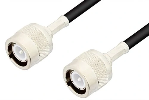
A connector that fits does not always mean the assembly is electrically correct.
This is a situation that appears frequently during RF sourcing. A buyer receives a sample, checks the mechanical dimensions, and confirms that both ends mate properly. The problem only appears after the cable is installed into the actual equipment.
The reason is simple: a coax cable assembly is a complete RF path. The cable, connector, termination method, and installation condition all affect the final measurement.
A cable assembly used at 900 MHz may have enough margin to tolerate small differences. The same assembly operating near several GHz can become much less forgiving.
Before selecting components, engineers usually need to look at three questions:
- How much loss can the system accept?
- How stable must the connection remain after installation?
- Which component becomes the limitation at the target frequency?
Check cable loss before focusing only on connector specifications
A common purchasing mistake is selecting the connector first because it is the most visible part of the assembly.
For example, an 18 GHz rated connector does not automatically create an 18 GHz capable cable assembly. If the selected cable has high attenuation at the operating frequency, the connector rating does not solve the problem.
Cable length has a direct effect. A short jumper inside a device and a several-meter antenna cable have completely different requirements.
| Item | Influence on RF Assembly |
| Cable length | Longer distance increases signal loss |
| Cable construction | Affects attenuation and flexibility |
| Connector quantity | Each transition may introduce loss |
| Adapter stack | Adds extra mismatch possibility |
| Assembly process | Influences repeatability |
In low-frequency applications, small differences may not create obvious problems. At higher frequencies, the same difference can appear during VNA testing.
This is why RF buyers should provide the operating frequency rather than only asking for a connector-to-connector cable.
Do not judge an RF connector only by appearance
Two connectors can look almost identical in a catalog image.
The internal dimensions may still be different.
The center contact position, dielectric support, cable entry design, and termination structure determine whether the connector works correctly with a specific cable.
SMA is a common 50Ω interface used in RF modules, antennas, and measurement systems. However, an SMA connector for RG316 is not necessarily interchangeable with one designed for RG58 or RG142.
The difference is usually located behind the mating interface:
- Cable entry diameter
- Ferrule size
- Crimp area
- Center pin design
- Shield connection method
A connector may pass a basic continuity check while the RF performance remains unstable.
For production orders, this difference matters because the first sample and the thousandth piece need to behave the same way.
How Should SMA Cable Assemblies Be Specified for Production?
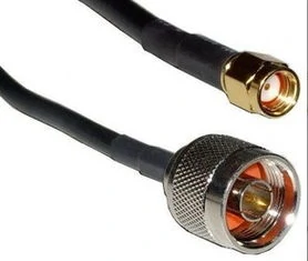
A coax cable assembly featuring SMA and N type connectors designed for reliable RF signal transmission. The assembly combines flexible coaxial cable with matched connectors for applications including wireless communication, antenna systems, and RF testing equipment.
SMA cable assemblies are widely used because they provide a compact solution for many RF connections. They appear in wireless equipment, test fixtures, communication devices, and antenna systems.
However, a purchasing request that only says “SMA cable” leaves too many details open.
Without these details, different suppliers may provide assemblies that look similar but produce different results.
Match the SMA connector with the cable structure
The cable and connector should be treated as a pair.
For example:
| Cable Model | Typical Consideration |
| RG178 | Very small diameter, suitable for compact routing |
| RG316 | Flexible RF wiring applications |
| RG405 | Semi-rigid applications requiring stable shape |
| RG142 | Higher power or lower-loss requirements |
The connector body must match the cable diameter and termination method.
During assembly production, several details affect the final connection:
- Strip length accuracy
- Center conductor alignment
- Braid contact condition
- Crimp force
- Solder temperature control
- Mechanical pull strength
A small deviation in these areas may not be visible from outside the connector.
Select connector orientation according to installation space
Cable routing is another factor often missed during ordering.
A straight SMA connector may work well on an open test bench but become difficult to install inside a compact enclosure.
Right-angle versions are often used when space is limited, but the bend area near the connector requires attention. Excessive pulling force or repeated bending at this point can damage the internal connection.
Before production, confirm:
- Straight or right-angle connector
- Cable exit direction
- Minimum bend radius
- Installation clearance
Use RF testing instead of relying only on appearance inspection
A finished assembly should be checked according to the application requirement.
Basic inspection may include:
- Connector type verification
- Cable length measurement
- Visual inspection
- Continuity testing
RF applications may additionally require:
- VSWR testing
- Return loss measurement
- Insertion loss testing
A continuity test only confirms that the conductor path is connected. It cannot identify every RF problem.
A cable assembly may pass continuity but show poor VSWR because of incorrect termination, damaged dielectric, or connector mismatch.
SMA Cable Assembly Specification Table
| Field | Example Requirement |
| Cable Model | RG316 / RG405 |
| Connector A | SMA Male |
| Connector B | SMA Female |
| Impedance | 50Ω |
| Frequency | Application operating range |
| Length | Finished cable length |
| Inspection | VSWR / Insertion Loss |
A clear specification allows the supplier to control production consistently. It also gives the buyer a reference when comparing samples from different sources.
How Does Cable Length Change the Behavior of a Coax Cable Assembly?
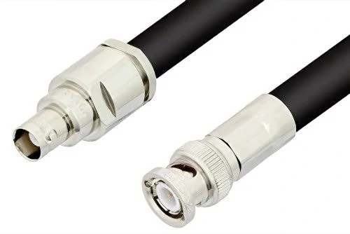
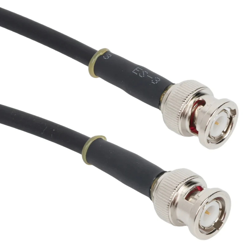
BNC coax cable assembly designed for test equipment, communication systems, and signal measurement applications. The BNC connector provides secure bayonet coupling while maintaining stable RF performance.
The cable length written on a purchase order looks like a simple mechanical dimension.
In RF applications, it is also an electrical parameter.
A 300 mm cable and a 3 m cable may use the same connector combination, but the longer version introduces more attenuation and gives installation conditions a greater influence on the final result.
This difference is easy to miss during prototype development. A short sample cable often has enough signal margin to perform well. Problems appear later when the production version becomes longer, passes through a different routing path, or operates closer to the frequency limit.
Before approving a coax cable assembly, engineers normally check the relationship between:
- Operating frequency
- Cable length
- Cable attenuation
- Connector quantity
- Required signal margin
Estimate loss before moving into production
A basic loss estimation can help during the selection stage.
This calculation does not replace RF testing, but it helps identify possible problems before samples are built.
For instance, an RG316 assembly may be suitable for a short internal connection. The same cable lengthened several meters may no longer be the preferred choice because attenuation becomes a larger part of the system budget.
| Situation | Possible Consideration |
| Short internal jumper | Flexibility and size may matter more |
| Long antenna connection | Lower attenuation may become a priority |
| High-frequency test cable | Connector quality and measurement stability become critical |
| Multiple adapters | Additional mismatch points should be reviewed |
A common mistake is adding adapters to solve a mechanical problem without considering the RF effect. Each additional connection creates another transition in the signal path.
Leave enough margin for real installation conditions
Laboratory samples are usually tested under controlled conditions.
Production equipment is different.
The final assembly may experience:
- Tight cable routing
- Repeated connection cycles
- Temperature changes
- Mechanical vibration
- Different installation operators
A design that works with almost no margin may become difficult to maintain during mass production.
For this reason, many engineers avoid selecting an assembly only according to the maximum listed frequency. The actual working environment matters just as much as the catalog specification.
What Information Should Be Included When Ordering a Custom Coax Cable Assembly?
Many cable assembly problems start with incomplete information.
A request such as:
“Need 1,000 pieces of SMA cable.”
does not define a production requirement.
The supplier still needs to know what cable, what SMA version, what length, and what acceptance standard are required.
A more useful RF request includes:
| Item | Example |
| Cable Model | RG316 |
| Connector End A | SMA Male |
| Connector End B | SMA Female |
| Length | 500 mm |
| Impedance | 50Ω |
| Frequency Range | DC–6 GHz |
| Quantity | Prototype / Production |
| Test Requirement | VSWR or insertion loss |
This information helps avoid unnecessary sample revisions.
Drawings become important for complicated assemblies
Text descriptions work well for simple jumper cables.
They become less effective when the assembly includes:
- Multiple bends
- Panel mounting connectors
- Fixed routing requirements
- Special connector orientation
- Defined installation space
A simple drawing showing cable direction and connector position can prevent misunderstanding between engineering and production teams.
The drawing does not need to be complicated. Even basic dimensions can remove uncertainty.
For example:
- Overall finished length
- Connector direction
- Bend location
- Mounting hole position
- Label location
These details are often the difference between a sample approval and several rounds of modification.
How Should Finished RF Cable Assemblies Be Checked Before Shipment?
A cable assembly can look correct and still fail an RF test.
Visual inspection is necessary, but it only covers part of the requirement.
A practical inspection process normally combines mechanical checks with electrical measurement.
Check the items that affect repeatability
Production inspection may include:
- Correct connector model
- Correct cable type
- Finished length measurement
- Connector appearance
- Strain relief condition
- Label confirmation
These checks prevent basic assembly mistakes.
For RF performance, additional testing may be required:
- Continuity test
- VSWR measurement
- Return loss test
- Insertion loss test
Each test answers a different question.
Coax Cable Assembly Acceptance Checklist
The following checklist can be used during sample approval or incoming inspection:
| Inspection Item | Check Method |
| Cable Model | Confirm against specification |
| Connector Interface | Verify type and gender |
| Cable Length | Measure finished assembly |
| Impedance | Confirm design requirement |
| Frequency Range | Match application |
| VSWR | Test if required |
| Insertion Loss | Test if required |
| Appearance | Visual inspection |
A clear acceptance standard reduces disagreement after delivery and makes repeated orders easier to control.
FAQ
What details should be provided for a custom coax cable assembly?
The supplier normally needs the cable model, connector combination, finished length, impedance, operating frequency, quantity, and required testing method. Complex assemblies may also require a mechanical drawing.
Can different connectors be used on each side of a coax cable assembly?
Yes. Assemblies such as SMA-to-N or SMA-to-BNC are common. The interface, impedance, and frequency range still need to match the RF system.
Does a longer coax cable always create problems?
Not necessarily. The effect depends on cable type, operating frequency, and acceptable signal loss. A longer assembly may work well when the cable selection matches the application.
Why can a cable assembly pass continuity but fail RF testing?
Continuity only checks the electrical connection. RF measurements can reveal problems caused by impedance mismatch, poor termination, or mechanical damage.
