
A cable assembly can pass a continuity test and still be the wrong RF part.
This happens more often than many buyers expect. The SMA connector mates correctly, the cable looks similar to the previous batch, and the first prototype works on the bench. The problem appears later when the cable is installed into a tighter enclosure, routed near other components, or operated closer to the upper frequency limit.
For RF systems, an SMA coax cable is not only a connector with a piece of wire attached. The connector interface, coaxial cable structure, termination method, impedance, and operating frequency all affect the final signal path.
This guide explains how to select an SMA coax cable based on connector configuration, cable type, frequency requirements, attenuation, and practical sourcing considerations.
How Does an SMA Coax Cable Connect RF Devices and Systems?
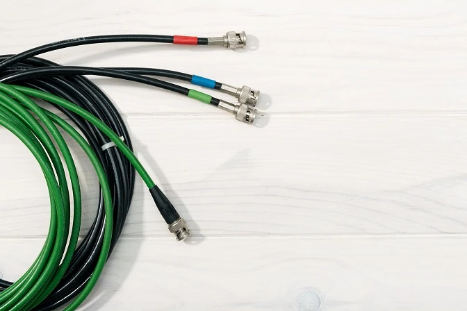
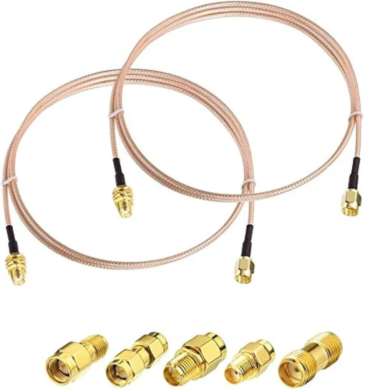
SMA cable assemblies can be customized with different connector combinations, including SMA male and SMA female interfaces, to meet different RF installation requirements.
An SMA coax cable is typically used as a flexible RF connection between two points in a signal chain. A complete cable assembly normally includes three parts:
- SMA connector interface
- Coaxial cable
- Cable termination structure
The connector provides the mechanical connection. The coaxial cable carries the RF signal. The termination process determines whether the electrical transition between connector and cable remains stable.
A common RF path may look simple:
RF Module → SMA Cable → Antenna / Test Equipment
However, every connection point introduces possible variables:
- connector gender mismatch
- incorrect impedance
- unsuitable cable diameter
- excessive cable length
- poor termination quality
A cable that physically fits does not always provide the expected RF performance.
Understand why SMA coax cables are widely used in compact RF applications
SMA coax cables are widely used because the SMA interface provides a compact threaded connection with good mechanical stability.
Typical applications include:
- wireless modules
- antenna connections
- RF evaluation boards
- communication equipment
- laboratory test systems
- microwave measurement setups
The SMA interface is commonly associated with 50Ω RF systems. This makes it suitable for many communication and test applications where impedance matching is required.
However, the connector itself does not determine the complete performance of the assembly.
A high-frequency SMA connector installed on a lower-performance cable may still become limited by cable attenuation or termination quality.
Identify where SMA coax cables fit in an RF signal chain
When selecting an SMA coax cable, engineers usually need to confirm four matching points:
- Connector interface
- Cable specification
- Operating frequency
- Installation environment
For example, an SMA cable used between a GPS module and antenna may prioritize flexibility and small diameter.
A cable used for VNA testing may require:
- lower insertion loss
- stable phase characteristics
- better VSWR control
- repeatable production quality
The same SMA interface can be used in different applications, but the cable construction may need to change.
Separate SMA coax cables from simple connector adapters
A common sourcing mistake is confusing an SMA coax cable with an SMA adapter.
An adapter only changes the interface between two connector standards.
Examples:
- SMA male to SMA female adapter
- SMA to N adapter
- SMA to 2.92 mm adapter
An SMA coax cable provides signal transmission through a cable path.
It is selected when the system requires:
- flexible routing
- additional installation distance
- connection between separated RF components
For a short laboratory connection, an adapter may solve the problem. For a device assembly or production system, a cable assembly is usually the correct approach.
How Do You Select the Correct SMA Connector Configuration?
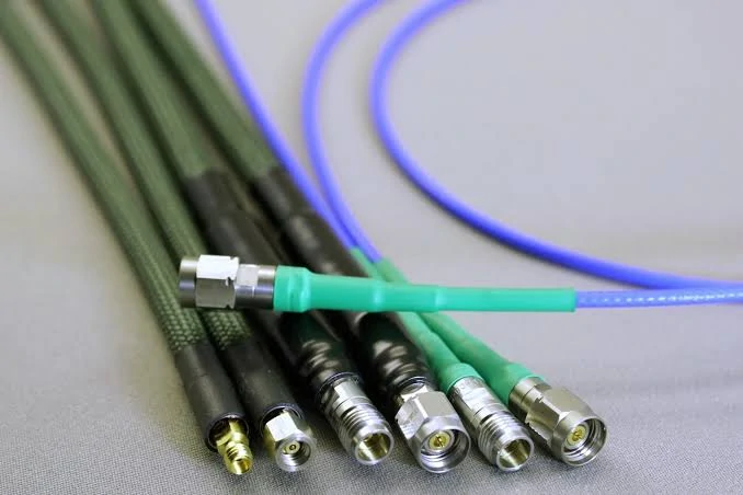
SMA coax cable assemblies are widely used in RF modules, antenna systems, and testing equipment. The connector type, cable structure, and frequency capability determine the overall RF performance.
The SMA connector side is the first specification that should be confirmed before ordering a cable.
Many production problems start from a simple mistake: the connector looks correct in the drawing, but the mating interface is wrong.
Choose SMA male connectors for cable-side applications
An SMA male connector normally has:
- center contact pin
- external thread
- plug-style interface
It is commonly installed on cable ends and connected to SMA female ports.
Typical applications include:
- RF jumper cables
- antenna cables
- module test cables
However, the rear cable termination must also match the cable type.
An SMA male connector designed for RG58 cable is not automatically suitable for RG316 or miniature coax cables.
The body size, ferrule, center pin, and termination structure must match the cable diameter and construction.
Choose SMA female connectors for equipment interfaces
An SMA female connector normally has:
- socket contact
- internal thread
- equipment-side mounting structure
It is commonly found on:
- RF modules
- PCB interfaces
- test equipment ports
When specifying an SMA female cable assembly, buyers should confirm whether the connector is:
- cable mount
- panel mount
- PCB mount
The mounting method affects mechanical installation and long-term reliability.
Confirm connector gender before ordering SMA coax cables
Before releasing a purchase order, the following information should be clearly defined:
| Check Item | Requirement |
| Connector Side A | SMA male / SMA female |
| Connector Side B | SMA male / SMA female |
| Impedance | 50Ω |
| Cable Type | RG316 / RG174 / 1.13mm / other |
| Length | Actual installed length |
| Application | Antenna, module, test, equipment |
A simple connector mismatch may stop assembly completely, even when the cable specification itself is correct.
For RF buyers, connector confirmation should happen before price comparison. A lower-cost cable with the wrong interface usually creates more cost during production.
SMA Connector Gender Selection Table
| Feature | SMA Male | SMA Female |
| Center Contact | Pin | Socket |
| Thread | External | Internal |
| Typical Side | Cable | Equipment |
| Common Use | RF jumper | Device interface |
| Identification | Visible pin | Recessed contact |
The connector interface is only the first step. Cable selection determines whether the assembly can maintain acceptable RF behavior after installation.
How Do Cable Structure and Materials Affect SMA RF Performance?
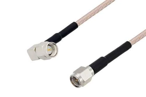
SMA male and SMA female connectors are commonly used in RF coax cable assemblies. Correct connector gender selection helps prevent installation problems and ensures proper signal connection.
Many SMA cable problems are not caused by the SMA connector itself.
A common situation in production is that a sample cable passes the initial test, but the same specification becomes unstable after mass production. The reason is often hidden inside the cable selection: different coaxial structures may have similar appearances but very different RF behavior.
For an SMA coax cable, the connector only defines the interface. The coaxial cable determines how much signal is lost, how easily the cable can be installed, and whether the assembly remains stable after repeated use.
Before placing an order, buyers should not only specify “SMA cable.” The cable type behind the connector is usually the part that decides whether the assembly fits the application.
Compare different coax cable structures for SMA applications
A coaxial cable is a complete RF structure, not just a conductor inside a jacket.
The main layers include:
- center conductor
- dielectric material
- shielding layer
- outer jacket
Small changes in these materials affect attenuation, flexibility, shielding effectiveness, and mechanical durability.
For SMA cable assemblies, common cable choices include RG316, RG174, RG178, miniature coax cables, and semi-rigid cables.
| Cable Type | Where It Usually Fits | Main Consideration |
| RG316 | Internal RF connection, short jumpers | Flexible but higher loss than larger cables |
| RG174 | General RF equipment | Good balance of size and cost |
| RG178 | Space-limited electronics | Small diameter, limited power capability |
| 1.13 mm coax | Wireless modules and antennas | Very compact, requires careful handling |
| Semi-rigid cable | Test fixtures and precision systems | Stable geometry, less flexible |
A buyer choosing between RG316 and RG174 should not only compare price.
The actual question is:
Where will the cable be installed, and how much RF loss can the system accept?
For example, an SMA-RG316 cable inside a communication module may be a reasonable choice because the cable length is short and routing space is limited.
The same cable may become unsuitable when used as a longer test cable operating near the upper frequency range.
Select cable diameter based on installation requirements
Cable diameter creates a trade-off that appears frequently in RF projects.
Smaller cables are easier to install.
They can pass through:
- narrow equipment spaces
- compact housings
- crowded PCB layouts
This is why miniature coax cables are common in GPS, Wi-Fi, LTE, and IoT products.
The problem appears when a design team increases cable length without reviewing the RF impact.
A smaller cable generally has higher attenuation. The additional loss may not be obvious during early prototype testing, especially when the test setup has strong signal margin.
During production, the same design may show:
- reduced receiving distance
- unstable wireless performance
- lower measurement repeatability
Larger coaxial cables usually provide better electrical margin, but they require more installation space.
This is why cable selection should happen together with mechanical design, not after the enclosure is finalized.
Balance flexibility and attenuation when choosing SMA cables
Flexibility is often requested by assembly teams because it makes installation easier.
But excessive flexibility usually comes from smaller cable construction, thinner conductors, or different dielectric structures.
The buyer needs to balance:
- minimum bend radius
- installation space
- cable length
- operating frequency
- acceptable insertion loss
A short SMA jumper inside equipment may prioritize flexibility.
A VNA test cable or calibration cable usually prioritizes stability and repeatability.
These two products may use the same SMA connector but require completely different cable structures.
SMA Coax Cable Selection Matrix
| Application | Recommended Cable Direction | Main Reason |
| Internal wireless module | RG316 / miniature coax | Easier routing |
| Short RF jumper | RG174 / RG316 | Cost and flexibility balance |
| Antenna connection | Depends on distance | Loss becomes important |
| Microwave testing | Low-loss or semi-rigid cable | Better measurement stability |
| Compact IoT device | Small diameter coax | Space limitation |
The mistake is not choosing a flexible cable.
The mistake is choosing a flexible cable without checking whether the RF budget allows it.
How Does Frequency Range Affect SMA Coax Cable Selection?
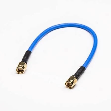
Flexible SMA coax cable jumpers are commonly used in wireless communication equipment, RF modules, and antenna connections where compact installation and reliable signal transmission are required.
A connector marked with a high-frequency rating does not guarantee the whole SMA cable assembly can operate at that frequency.
A typical SMA assembly includes:
SMA connector → termination area → coaxial cable → termination area → SMA connector
Each transition can introduce loss or mismatch.
At lower frequencies, small manufacturing differences may not create obvious problems.
At microwave frequencies, the same differences become measurable.
Match SMA cable specifications with operating frequency
Before selecting an SMA coax cable, the buyer should define:
- working frequency range
- cable length
- acceptable insertion loss
- VSWR requirement
- installation condition
For example, a cable used in a 2.4 GHz wireless device and a cable used in an 18 GHz laboratory setup should not be selected using the same standard.
The second application normally requires tighter control of:
- connector geometry
- assembly process
- cable consistency
- inspection method
Frequency selection should include some margin.
A cable operating continuously close to its maximum specification leaves less room for production variation.
Understand why high frequency systems require better cable quality
High-frequency RF assemblies expose problems that low-frequency testing may not reveal.
Typical issues include:
- center contact misalignment
- damaged dielectric
- incomplete shielding contact
- inconsistent soldering
- poor crimping
A continuity test only confirms that electricity can pass through the cable.
It does not confirm:
- insertion loss
- return loss
- VSWR
This is why production RF cable suppliers usually combine electrical testing with mechanical inspection.
For high-frequency SMA assemblies, a simple “looks correct” inspection is not enough.
Select suitable SMA cables for microwave applications
Microwave applications usually have stricter requirements.
Typical examples:
- vector network analyzer connection
- microwave module testing
- RF calibration equipment
- laboratory measurement systems
For these applications, buyers often care about:
| Parameter | Why It Matters |
| VSWR | Shows mismatch level |
| Insertion Loss | Shows signal reduction |
| Return Loss | Shows reflected energy |
| Phase Stability | Important for measurement repeatability |
| Connector Repeatability | Important for repeated mating |
A cable assembly specification should be written clearly.
Instead of:
“SMA cable, 1 meter”
A more useful BOM description would be:
“SMA male to SMA female cable assembly, 50Ω, RG316, 1000 mm length, operating frequency DC–6 GHz, tested for continuity and VSWR.”
The additional details reduce the possibility of receiving a similar-looking but unsuitable replacement.
How Do You Calculate Signal Loss in SMA Coax Cables?
Cable length is one of the easiest specifications to overlook.
During prototype development, engineers often use a short cable because it is convenient for testing.
After the product moves into production, the cable routing may become longer because of enclosure changes.
The additional length increases RF loss.
The calculation requires:
| Parameter | Example Input |
| Cable Type | RG316 / RG174 / Low Loss Cable |
| Frequency | Operating GHz |
| Cable Length | Actual installed length |
| Attenuation | dB/m at working frequency |
| Connector Quantity | Number of RF transitions |
| Total Loss | Estimated dB |
The formula does not replace laboratory measurement, but it helps prevent obvious specification mistakes.
Understand why longer SMA cables require lower attenuation
A longer cable creates additional loss.
The effect becomes stronger when:
- frequency increases
- cable diameter decreases
- signal margin is limited
This is why antenna feeder cables often use larger low-loss coax instead of miniature cables.
A compact cable may be perfect for a 100 mm internal connection but unsuitable for a 3-meter external antenna path.
The application decides the cable.
Not the connector name.
Compare standard SMA cables with low loss solutions
Low-loss SMA cable assemblies are normally considered when the system has limited RF margin.
Typical cases include:
- long cable routing
- high-frequency measurement
- weak received signals
- precision RF testing
But low loss is not the only requirement.
A larger low-loss cable may create problems if:
- the enclosure cannot support the bend radius
- the connector is under mechanical stress
- the assembly cannot be installed consistently
Good RF sourcing is usually a compromise between electrical performance and production reality.
The best specification is the one that matches the actual system condition.
How Are SMA Coax Cables Tested Before Use?
The cable passed the bench test. The production batch still failed.
This situation is not unusual for RF assemblies.
A prototype cable is often tested under ideal conditions: short length, straight routing, clean connector mating. After installation, the cable may be bent, pulled, placed close to other components, or produced by a different operator.
The electrical path has changed.
That is why SMA coax cable inspection cannot rely only on appearance or a simple continuity check.
Check the details that are easy to miss during assembly
Most SMA cable problems do not start from the front connector interface.
They appear during termination.
Typical issues include:
- incorrect cable stripping length
- poor solder control
- incomplete shielding contact
- damaged dielectric during assembly
- loose crimp connection
These problems are difficult to find from photos.
A cable may have the correct SMA male connector and the correct cable model, but the transition between the connector and coax cable may already affect RF performance.
For production orders, suppliers normally need to control:
- connector installation
- cable length tolerance
- pulling strength
- appearance inspection
For higher-frequency applications, mechanical consistency becomes more important because small geometry changes can affect the RF path.
Why continuity testing is not enough
Continuity testing is useful, but it only answers one question:
“Is the conductor connected?”
RF engineers usually need more information.
A cable can pass continuity and still show:
- high VSWR
- excessive insertion loss
- poor return loss
This is why test requirements should be discussed before production, not after a quality issue appears.
For example:
A short SMA-RG316 jumper inside equipment may only require basic inspection.
A cable used for RF measurement equipment may require VNA testing because repeatability matters more than cost.
When Does an SMA Cable Become an SMA Cable Assembly?
During early development, engineers often describe the product simply as an “SMA cable.”
After entering production, the specification usually becomes more detailed.
The difference is not only the name.
A production cable assembly represents a controlled manufacturing process.
The supplier needs to know:
- connector combination
- cable structure
- finished length
- tolerance requirement
- testing method
- packaging method
A drawing that only shows:
“SMA to SMA cable, 500 mm”
still leaves many questions unanswered.
Which SMA?
Male to male?
Male to female?
RG316 or RG174?
DC–6 GHz or DC–18 GHz?
These details directly affect whether the assembly can be used.
Why production buyers need clearer specifications
A common purchasing mistake is treating RF cables like ordinary wires.
Two cables may look almost identical but use different internal structures.
The difference may come from:
- dielectric material
- shielding design
- connector machining
- termination process
For small quantities, this may only create a testing inconvenience.
For thousands of pieces, it can become a production problem.
A clear BOM specification reduces unnecessary replacement and communication time.
How Should SMA Cables Be Compared With Other RF Solutions?
SMA is popular because it is compact and easy to integrate.
But it is not automatically the right choice.
A compact wireless module and an outdoor antenna system have completely different requirements.
| Application | Possible Solution | Reason |
| Internal RF module | SMA cable | Small size, easy routing |
| Outdoor antenna connection | N Type cable | Better mechanical strength |
| Test equipment | SMA/BNC solution | Measurement convenience |
SMA cable assemblies are often selected for:
- RF modules
- communication devices
- laboratory equipment
- antenna connections
N Type assemblies are more common when the cable faces:
- outdoor installation
- weather exposure
- mechanical stress
The connector is only one part of the decision.
The cable length, frequency, environment, and installation method all affect the final choice.
What Information Should Be Sent When Ordering SMA Coax Cables?
Many RF sourcing problems start with an incomplete request.
A supplier receives:
“Need SMA cable, 1 meter.”
That description is not enough for a production quotation.
A useful specification normally includes:
| Item | Example |
| Connector | SMA male to SMA female |
| Cable | RG316 |
| Impedance | 50Ω |
| Length | 1000 mm |
| Frequency | DC–6 GHz |
| Test | VSWR requirement |
For custom SMA coax cables, additional details may include:
- bending requirement
- installation space
- connector plating
- labeling
- batch inspection method
These details help the supplier understand the actual application instead of only matching a connector shape.
FAQ
Can the same SMA cable be used for different frequency ranges?
Not always. A cable that works well at a lower frequency may show higher loss or mismatch when used closer to the upper operating limit.
Why does my SMA cable have the correct connector but still show poor RF performance?
The SMA interface may be correct, but the complete cable assembly includes more than the connector.
Problems can come from the termination area, cable selection, shielding contact, or impedance transition.
This is why two SMA cables with the same connector combination can produce different test results. The connector model alone does not define the performance of the entire assembly.
Why can two SMA cables with the same connectors show different RF results?
This usually happens when the cable part behind the connector is different.
The SMA interface may look identical, but the cable type, length, termination process, or assembly tolerance can change the result.
A replacement cable should be checked against the original specification. Matching only “SMA male to SMA female” is not enough for RF applications.
What details should I provide when asking for a custom SMA cable quotation?
A supplier usually needs more than the connector name.
The basic information should include:
- connector type on both ends
- cable model
- finished length
- operating frequency
- impedance requirement
For production orders, it is also useful to provide the installation condition and inspection requirements.
