
Building the Right RF Signal Path Through Cable Assemblies
A cable assembly can pass a continuity test and still be the wrong RF part.
This happens more often than many buyers expect. The connector mates correctly, the cable length looks acceptable, and the first prototype works on the bench. The problem appears later when the assembly is installed inside a device, bent around a chassis, exposed to vibration, or tested near the upper frequency limit.
A coaxial cable assembly is not simply a piece of coaxial cable with connectors attached at both ends. It is a complete RF transmission component that combines the cable structure, connector interface, termination process, and electrical verification.
How Does a Coaxial Cable Assembly Create a Complete RF Signal Path?
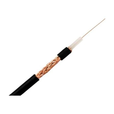
This image illustrates the internal construction of a coaxial cable, including the center conductor, dielectric insulation, shielding layer, and outer jacket. Different cable structures influence RF transmission loss, frequency range, and mechanical flexibility.
A typical coaxial cable assembly includes:
- Coaxial cable
- RF connectors
- Connector termination structure
- Strain relief or protection components
- Electrical testing and inspection records
The cable determines many electrical characteristics, including attenuation, shielding effectiveness, flexibility, and frequency capability. The connector determines how the assembly interfaces with the equipment and whether the RF transition remains stable.
This is why two assemblies using the same connector type may not perform the same way.
For example, an SMA connector installed on RG316 cable is not equivalent to an SMA connector installed on RG142 cable. The interface may look identical from the outside, but the cable diameter, dielectric structure, shielding layer, and termination method are different.
A correct assembly requires matching:
| Parameter | Why It Matters |
| Connector interface | Determines mechanical connection and RF transition |
| Cable type | Affects loss, flexibility, and frequency capability |
| Impedance | Prevents signal reflection |
| Length | Directly affects total attenuation |
| Termination method | Influences consistency and reliability |
| Test requirement | Confirms actual RF performance |
A common sourcing mistake is specifying only:
“Need SMA cable.”
This description is incomplete for production use.
A proper RF cable assembly request should include connector gender, cable model, length, impedance, operating frequency, quantity, and application environment.
Where Are Coaxial Cable Assemblies Used in RF Systems?
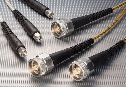
This image shows multiple RF coaxial cable assemblies with different connector configurations. Cable assemblies are selected according to connector type, cable specification, frequency range, impedance requirements, and application environment.
Coaxial cable assemblies are widely used wherever RF signals need to move between separated components.
This difference is often overlooked during purchasing.
A cable assembly that works well inside a laboratory may not be suitable for outdoor installation. Likewise, a flexible cable that is easy to route may introduce more loss than a larger low-loss cable.
The application environment should be considered before selecting the assembly.
Match the Cable Assembly With the Complete RF Transmission Chain
The cable assembly should be selected as part of the entire RF system, not as an independent component.
A typical RF path may look like:
RFtransmitter → SMA cable assembly → filter → adapter → antenna
Every additional connection introduces possible loss and mismatch.
For high-frequency systems, adapter quantity and connector transitions become increasingly important. A connection that appears mechanically correct may still create RF problems if the impedance transition is not controlled.
For example, adding multiple adapters between different connector standards may increase insertion loss and affect return loss. In measurement applications, this can introduce errors that are difficult to identify because the cable itself may appear normal.
This approach reduces the risk of receiving a cable assembly that fits mechanically but fails electrically.
Why Cable and Connector Matching Matters During Production
Prototype samples often hide problems.
A short sample cable installed in a controlled environment may perform well. Production assemblies can behave differently because of:
- Different cable routing
- Longer cable length
- Different bending radius
- Assembly variation
- Connector installation tolerance
For RF production, repeatability is as important as the first test result.
A professional cable assembly supplier should control not only the connector and cable selection but also the termination process. Important manufacturing details include:
- Center pin alignment
- Shield contact quality
- Crimping consistency
- Soldering temperature control
- Cable stripping dimensions
- Final RF testing
Visual inspection can confirm appearance, but it cannot confirm high-frequency behavior.
A cable assembly may look perfect and still show excessive VSWR when measured with a vector network analyzer.
Practical Selection Rule for Buyers
Before requesting a quotation for a coaxial cable assembly, prepare the following information:
| Required Information | Example |
| Connector A | SMA Male |
| Connector B | N Female |
| Cable Type | RG58 / RG316 / LMR series |
| Impedance | 50Ω |
| Length | 1 m |
| Frequency Range | DC–6 GHz |
| Quantity | 100 pcs |
| Application | Antenna / Test / Communication |
Providing complete specifications helps suppliers select the correct cable structure and avoid unnecessary replacements caused by incomplete requirements.
A coaxial cable assembly is a small component in an RF system, but it directly affects signal quality. Selecting it correctly requires looking beyond the connector shape and considering the complete transmission path.
Selecting Cable Types, Connector Combinations, and RF Performance Requirements
A cable assembly can have the correct connector on both ends and still fail the application.
One common mistake during sourcing is focusing only on the connector interface. Engineers may confirm that an SMA, N Type, or BNC connector physically mates with the equipment, but ignore whether the cable structure behind the connector can support the required frequency, loss target, and installation condition.
The connector is only one part of the RF path.
The cable diameter, dielectric material, shielding structure, and termination method all affect the final performance of the coaxial cable assembly.
For this reason, cable and connector selection should always be performed together.
How Do You Select Cable and Connector Combinations for RF Assemblies?
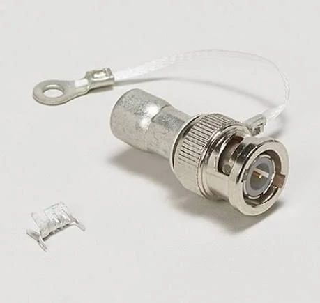
This image shows a coaxial cable assembly structure, including the RF connector interface, cable connection section, and mechanical protection components. Proper matching between the connector and cable type is essential for stable RF performance, impedance control, and reliable signal transmission.
Different RF applications require different connector combinations.
A compact SMA assembly may be suitable for an RF module or test port, while an N Type cable assembly is often selected for antenna systems where mechanical strength and environmental resistance are more important.
The correct choice depends on both electrical and mechanical requirements.
Match Connector Types With RF Application Requirements
The following table shows common RF connector choices used in coaxial cable assemblies.
| Connector Type | Typical Application | Main Consideration |
| SMA | RF modules, wireless devices, test equipment | Compact size and wide frequency availability |
| N Type | Antenna systems, communication equipment | Strong mechanical structure and outdoor suitability |
| BNC | Test instruments, measurement equipment | Quick locking connection |
| TNC | Mobile communication and vibration environments | Threaded coupling with better mechanical stability |
| 2.92 mm / 3.5 mm / 2.4 mm | Microwave and high-frequency testing | Precision interface control |
The connector rating alone does not define the assembly performance.
For example, a high-frequency SMA connector installed on an unsuitable cable may not achieve the expected operating frequency. The cable becomes the limiting factor.
A 26.5 GHz connector does not automatically create a 26.5 GHz cable assembly.
The complete assembly must be evaluated as a system.
Select Cable Structure According to Connector Compatibility
Each coaxial cable family has its own mechanical characteristics.
The connector rear section must match the cable diameter and construction.
Important matching factors include:
- Outer diameter
- Dielectric diameter
- Shielding layers
- Center conductor size
- Termination method
A connector designed for RG316 cable cannot simply replace a connector designed for RG58 cable, even if both use an SMA interface.
The difference appears during assembly.
A poor match may cause:
- Weak cable retention
- Poor shield contact
- Incorrect center pin position
- Increased VSWR
- Reduced mechanical reliability
For production quantities, this mismatch can create repeated failures that are difficult to solve after assembly.
Why Connector Compatibility Is More Than Mechanical Matching
A connector can physically connect while still creating an RF problem.
This is especially important when different connector families or adapters are involved.
For example:
Equipment → Adapter → Cable Assembly
Each transition introduces another RF interface.
Every additional interface may affect:
- Insertion loss
- Return loss
- VSWR
- Mechanical stability
A common mistake is adding adapters to solve a mechanical mismatch without checking RF performance.
For low-frequency applications, the effect may be acceptable.
For microwave systems, measurement equipment, or sensitive communication links, the additional transition may become a problem.
Before replacing or modifying a cable assembly, confirm:
- Interface type
- Gender
- Impedance
- Frequency range
- Connector specification
- Required test standard
How Do Cable Specifications Affect Coaxial Assembly Selection?
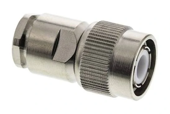
This image shows an N Type RF coaxial connector commonly used in antenna systems, communication equipment, and outdoor RF applications. N Type connectors provide strong mechanical performance and are suitable for applications requiring stable RF connections.
The cable inside the assembly determines many of the final RF characteristics.
Different cable types are designed for different priorities:
- Lower loss
- Higher flexibility
- Smaller diameter
- Better shielding
- Higher power capability
- Higher frequency operation
There is usually no cable that provides every advantage at the same time.
A larger low-loss cable may provide better attenuation performance but become difficult to install in compact equipment.
A thin flexible cable may simplify routing but introduce higher signal loss.
The correct selection depends on the system requirement.
Choose Cable Types According to Frequency and Attenuation Requirements
Frequency is one of the first parameters to confirm.
A short internal connection may prioritize flexibility.
A long antenna feed line may require lower attenuation.
Balance Flexibility and RF Performance
Many buyers want a cable assembly that is:
- Thin
- Flexible
- Low loss
- High frequency
- Low cost
In practice, these requirements often conflict.
A larger cable usually has lower attenuation because of its construction. However, larger diameter cables have a larger bending radius and require more installation space.
A simple RF loss calculation can help determine whether the selected cable type is appropriate.
Calculate Total RF Transmission Loss Before Ordering
The actual loss depends on frequency, connector design, and manufacturing quality, but this calculation helps during initial selection.
Why Longer Cable Assemblies Need More Attention
A longer cable does not only increase physical size. It increases RF loss.
This becomes more noticeable in:
- High-frequency systems
- Weak signal applications
- Long antenna connections
- Precision measurement systems
For example, replacing a short laboratory cable with a longer production cable may change measurement results even if the connector type remains unchanged.
This is why cable length should always be included in the RF specification.
Standard Cable Assembly vs Low Loss Cable Assembly
A standard assembly may be sufficient for:
- Short internal connections
- General communication equipment
- Low-frequency applications
A low-loss cable assembly is usually considered when:
- Cable length is longer
- Frequency is higher
- Signal power is limited
- Measurement accuracy is important
However, low-loss does not always mean the best choice.
A large low-loss cable may not fit inside a compact enclosure.
The correct selection is a balance between:
- Electrical loss
- Mechanical installation
- Cost
- Production requirements
Testing Methods, Custom Cable Assembly Requirements, and Supplier Evaluation
A cable assembly usually fails at the stage where engineers assume everything is already correct.
The connector fits. The cable length is close. The signal appears on the screen.
Then the problems start.
A production batch shows unstable VSWR. A measurement system gives different results from the prototype. A cable routed through the final enclosure introduces unexpected attenuation.
The reason is simple: RF cable assemblies are sensitive to details that are often ignored during early selection.
A coaxial cable assembly is not finished when the connector is attached. The termination quality, cable preparation, mechanical stress, and final RF verification determine whether the assembly can perform consistently.
How Can RF Cable Assemblies Be Verified Before Production Use?
A common misunderstanding is that electrical continuity testing is enough.
It is not.It cannot detect problems such as impedance discontinuity, excessive insertion loss, or poor connector transitions.
For low-frequency applications, this basic check may be acceptable.
For RF systems operating at several GHz, the inspection method needs to match the application.
Check Mechanical Details Before Measuring RF Performance
Many RF problems start during assembly rather than during design.
Small manufacturing differences can affect the final result.
Examples include:
- Cable stripping length variation
- Incorrect crimp position
- Damaged shielding braid
- Center pin misalignment
- Excessive soldering temperature
- Connector not fully seated
These issues may not be visible from the outside.
A cable assembly can look clean while the internal connection is already affecting RF performance.
This is especially important for OEM customers. A single sample cannot represent long-term production stability.
Why Does RF Testing Matter More at Higher Frequencies?
At low frequencies, some assembly errors may have limited impact.
At higher frequencies, the same mechanical variation can become measurable.
For example, a slightly poor connector transition may have little effect at hundreds of MHz but create noticeable return loss variation at microwave frequencies.
Common RF tests include:
VSWR Test
VSWR indicates how well the assembly matches the RF system impedance.
A higher value may come from:
- Connector mismatch
- Poor termination
- Damaged cable structure
- Incorrect cable selection
Insertion Loss Test
Insertion loss shows how much signal power is lost through the assembly.
The result depends on:
- Cable type
- Cable length
- Frequency
- Connector quantity
- Manufacturing quality
A longer cable assembly will normally require more attention to cable attenuation.
VNA Measurement
For demanding applications, a vector network analyzer provides a more complete view.
It can evaluate:
- Return loss
- VSWR
- Insertion loss
- Frequency response
For test cables and microwave assemblies, VNA verification is often more meaningful than simply checking whether the signal passes.
When Does a Standard Cable Assembly Become the Wrong Choice?
Standard assemblies are useful when the equipment interface and cable requirements are already common.
However, many industrial applications do not fit standard combinations.
A custom coaxial cable assembly may be required when:
- The equipment has uncommon interfaces
- The cable routing space is limited
- A specific length is required
- The assembly must fit an existing structure
- The customer needs repeat production
A typical custom request is not only:
“Make this cable longer.”
The supplier needs to understand:
- What connector is required on each end?
- What frequency range is needed?
- What cable type fits the installation?
- Is the assembly for testing or final equipment?
- What inspection standard is required?
Connector Combination Is Often the First Custom Challenge
Many RF systems use different connectors on each side.
For example:
- SMA to N Type
- BNC to SMA
- TNC to N Type
- MMCX to SMA
This is normal in RF systems because different devices are designed with different interfaces.
However, the connection should not be selected only by appearance.
The supplier needs to check:
- Interface compatibility
- 50Ω impedance
- Frequency capability
- Mechanical strength
- Cable matching
A wrong connector-to-cable combination can create problems that are difficult to diagnose after installation.
How Should Buyers Evaluate an RF Cable Assembly Supplier?
Price is usually easy to compare.
Technical capability is harder.
Two suppliers may quote the same connector and cable description, but the actual assembly quality can be different.
For production purchasing, buyers should pay attention to several points:
| Evaluation Item | What Buyers Should Confirm |
| Cable source | Is the cable specification stable? |
| Connector matching | Is the connector designed for this cable? |
| Assembly process | Are stripping and termination controlled? |
| Testing ability | Can the supplier perform RF tests? |
| Production consistency | Can repeated orders maintain the same result? |
A supplier that can provide one sample is not necessarily ready for volume production.
For repeated orders, consistency is usually more valuable than a slightly lower initial price.
What Information Should Be Included in an RF Cable Assembly Request?
Many quotation delays happen because the request only includes a connector name.
For example:
“Need SMA cable, 500 pcs.”
This does not define the actual product.
FAQ
Does using a higher-frequency connector improve the whole cable assembly?
Not necessarily. The cable type, termination quality, and connector-to-cable matching also determine the final frequency capability.
Why do production cable assemblies sometimes perform differently from samples?
Production variation may come from cable routing, termination consistency, connector installation, and testing differences.
Should every RF cable assembly receive VNA testing?
Not every application requires VNA testing. The required inspection level depends on frequency, application risk, and performance requirements.
Why can two coaxial cable assemblies with the same connector perform differently?
The connector interface is only one part of the assembly.
Two cable assemblies using the same SMA or N Type connector may perform differently because the cable type, dielectric structure, shielding design, cable diameter, and termination process are not the same.
For example, an SMA assembly using RG316 cable is not interchangeable with an SMA assembly using RG142 cable. The external connector may look similar, but the internal electrical characteristics and mechanical requirements are different.
Why do RF buyers need to provide cable type and frequency when requesting a quotation?
Because “RF cable” is not a complete specification.
The same connector can be assembled with different cable families, and each cable has different attenuation, flexibility, size, and frequency capability.
Providing cable type, length, frequency range, and application helps avoid selecting an assembly that fits mechanically but does not meet the RF requirement.
