
A TNC-to-SMA connection can look correct on the bench and still be a poor installation.
The threads mate, continuity passes, and the first RF check may even look acceptable. Then the assembly is installed in an enclosure. A heavier cable pulls sideways on the SMA port, the route needs a tighter bend than expected, or the two equipment ports sit at slightly different angles. What looked like a simple connector conversion becomes a mechanical problem as much as an RF one.
That is where a TNC to SMA cable can make more sense than a rigid adapter.
Instead of forcing two unlike interfaces into a fixed mechanical relationship, a short coaxial assembly gives the installation some compliance. The TNC side can remain on the larger, more rugged equipment interface while the SMA side reaches a compact radio, module, receiver, test port, or internal bulkhead.
The useful design question is not simply, “Can TNC connect to SMA?”
It is:
Which connector ends, cable construction, length, routing geometry, and mounting arrangement will still work after the assembly is installed?
Where should a flexible TNC-to-SMA link sit in the RF chain?
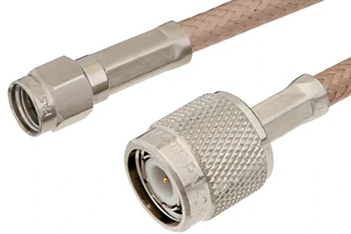
TNC-to-SMA coaxial cable assembly featuring a larger threaded TNC connector and a compact SMA connector for RF equipment interconnection.
Start by drawing the actual RF path.
A typical arrangement may look like this:
TNC antenna or radio port → coaxial cable → SMA module or instrument
That sounds obvious, but many sourcing errors happen because the buyer specifies only the two connector names. The mechanical role of the cable is never defined.
Consider an outdoor radio with a TNC interface feeding a compact receiver board inside an enclosure. The TNC side may be expected to tolerate repeated field mating, vibration, or a relatively heavy external feeder. The SMA side may sit on a small RF module where excess bending force is undesirable.
In that installation, the cable assembly is not just changing connector families. It is also acting as a mechanical transition between two very different pieces of hardware.
The same logic applies to several common layouts:
- TNC antenna to SMA gateway
- Outdoor radio to SMA receiver
- Vehicle antenna system to SMA electronics
- Rugged RF enclosure to compact internal module
- TNC bulkhead to SMA test port
- TNC-equipped radio to SMA-based measurement hardware
The route matters because a connector that is mechanically comfortable in one location may be awkward in another.
Separate the cable assembly from a rigid TNC/SMA adapter
A TNC to SMA cable assembly and a rigid TNC/SMA adapter solve related interface problems, but they should not be treated as interchangeable parts.
A rigid adapter works well when the two mating directions are already aligned and the resulting assembly does not create excessive leverage on either equipment port.
A cable assembly becomes more useful when:
- The ports are offset.
- The two mating axes do not line up.
- The connection must route around another component.
- Vibration or service movement is expected.
- One connector sits on a delicate module.
- The cable needs to be clamped independently of the equipment connector.
- A right-angle transition alone cannot solve the routing problem.
A short RF pigtail may also reduce the temptation to build a chain of rigid adapters.
That matters because every extra interface creates another place where mechanical looseness, mismatch, contact damage, or additional RF loss can enter the signal path.
A rigid stack also moves as one piece. If a heavy TNC-side cable is attached to that stack, the resulting leverage can be transferred directly to the smaller SMA port.
Flexibility is useful here, but only if the cable itself is selected correctly. Replacing a rigid adapter with an excessively stiff coax does not fully solve the problem.
Use cable compliance when the ports cannot align safely
The word “flexible” should not be interpreted as “anything will fit.”
The goal is controlled compliance.
The assembly should absorb reasonable alignment and routing differences without forcing the connector body, cable termination, or equipment port to carry loads it was not intended to handle.
Before releasing the BOM, check five installation conditions:
- Port alignment — Are the TNC and SMA mating axes naturally aligned?
- Cable torque — Will the cable try to rotate the SMA connector after installation?
- Bending location — Does the cable begin bending immediately behind the connector?
- Equipment vibration — Will repeated movement reach either termination?
- Service movement — Will technicians frequently disconnect, move, or reposition the cable?
A cable assembly that passes a straight bench test may behave differently after being bent, clamped, and installed. That installed geometry should be considered during selection, not after the first production batch arrives.
Which TNC and SMA end combination actually matches the equipment?
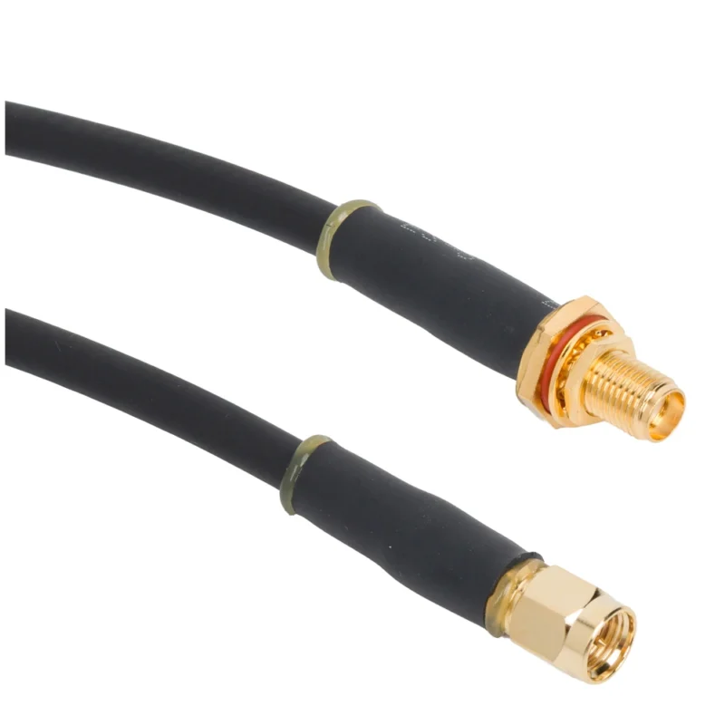
Do not select gender from the product title alone.
Identify each equipment port separately.
On the TNC side, confirm the connector body and the center contact. A TNC plug normally mates with the corresponding TNC jack, but purchasing mistakes still occur when a drawing shows only the external thread or when supplier photos hide the center contact.
Record:
- TNC male or female
- Center pin or socket
- Standard or reverse polarity, where applicable
- Equipment mating interface
- 50-ohm requirement
- Cable-mounted or bulkhead-mounted connection
Then repeat the same check independently for the SMA side.
Confirm the SMA interface independently
The SMA side may be:
- SMA male
- SMA female
- SMA female bulkhead
- SMA male bulkhead
- A cable connector
- A panel-mounted connector
Standard SMA and reverse-polarity SMA should also be separated during specification. A part that appears mechanically similar in a small supplier photo may not have the center-contact arrangement required by the equipment.
For mixed-interface cables, common combinations can include:
- TNC male to SMA female cable
- TNC female to SMA male cable
- TNC male to SMA male cable
- TNC female to SMA female cable
None of these combinations is inherently “correct.” The correct version is the one that mates with the two actual device ports.
This sounds basic, but it is one of the cheapest errors to prevent before production and one of the most irritating to discover after finished cable assemblies are labeled and packed.
Build a two-port mating record before requesting a quote
A simple interface record makes supplier communication much clearer.
| Field | TNC Side | SMA Side |
| Connected device | ||
| Connector gender | ||
| Center contact | Pin / Socket | Pin / Socket |
| Polarity | Standard / Other | Standard / RP |
| Impedance | ||
| Required frequency | ||
| Mounting style | Cable / Bulkhead | Cable / Bulkhead |
| Drawing or photo reference |
How do you choose RG316, RG58, or LMR240 for the assembly?
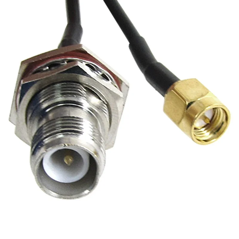
Do not start with the lowest-loss cable.
Start with the installed route.
A cable with lower attenuation can still be the wrong choice if its diameter, stiffness, or minimum bend radius puts too much load on the SMA connector. This becomes especially relevant in a TNC-to-SMA transition because the two ends often serve very different mechanical environments.
RG316, RG58, and LMR240-class coax can all appear in this type of assembly, but they solve different problems.
Use RG316 when flexibility and compact routing dominate
RG316 is usually the easier starting point for short equipment jumpers where space is limited.
Its smaller diameter and relatively flexible construction make it useful for:
- Short internal RF links
- Test racks
- Enclosure wiring
- Tight routing around PCBs or modules
- Reducing mechanical load near the SMA end
- Short transition sections between a larger feeder and compact hardware
That does not mean RG316 should automatically be selected for every compact assembly. Cable attenuation still increases with frequency and length.
A 150 mm jumper and a 2 m antenna run are very different RF problems.
For short connections, the mechanical advantage of RG316 may outweigh its higher attenuation compared with a larger low-loss cable. Once the run becomes longer, the loss budget needs to be checked before the cable is released.
For more cable-specific sourcing considerations, the RG316 cable selection guide can be used separately. In this TNC-to-SMA assembly, the key question is whether RG316 gives enough RF margin while keeping the SMA side mechanically comfortable.
Move to RG58 when the route is longer and space permits
RG58 is physically larger and normally less convenient in a very tight enclosure, but it can make more sense when the cable run becomes longer or the assembly needs more handling robustness.
Typical situations include:
- Equipment-to-antenna runs
- Rack interconnects with more routing space
- General-purpose 50-ohm RF assemblies
- Installations where a larger cable is easier to clamp and support
The important caution is at the SMA end.
A heavier cable should not simply be allowed to hang from a small panel connector or module-mounted SMA port. If RG58 is selected, define the first support point and the bend behind the connector.
The RG58 cable guide can provide the broader cable discussion. For this mixed-interface assembly, the useful decision is whether its lower loss and increased size justify the additional routing and strain-relief requirements.
Use LMR240-class cable when attenuation becomes the dominant limit
Longer outdoor runs can push the design toward a lower-loss cable family.
That may improve RF loss, but it changes the mechanical problem again.
A larger cable can introduce:
- Higher connector leverage
- Larger bend radius
- More difficult SMA-side termination
- Greater clamp requirements
- Less tolerance for tight enclosure routing
If a low-loss feeder reaches a small SMA device directly, the electrical improvement may come with a mechanical penalty.
One practical architecture is to keep the lower-loss cable for the main run and use a short, more flexible transition close to the SMA equipment. Whether that is acceptable depends on the added connector interfaces and the total RF budget.
The following matrix is more useful than a simple “lowest loss wins” comparison.
| Selection Factor | RG316 | RG58 | LMR240-Class |
| Relative diameter | Small | Medium | Larger |
| Flexibility | High | Medium | Lower |
| Relative attenuation | Higher | Medium | Lower |
| Tight routing | Good | Moderate | Limited |
| SMA-side port-load risk | Lower | Medium | Higher without support |
| Typical use | Short jumpers | General RF runs | Longer low-loss runs |
| Strain-relief need | Moderate | Important | Critical |
| Best design question | Is the loss acceptable? | Is there enough routing space? | Can the cable be mechanically supported? |
TNC-to-SMA Coax Selection Matrix
Exact attenuation should still come from the selected cable manufacturer’s datasheet. Do not substitute a generic cable-family value into a production RF specification.
How long can the cable be before loss becomes unacceptable?
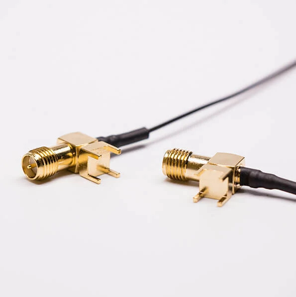
Two right-angle SMA connectors attached to miniature coaxial pigtail cables, showing a compact routing option for PCB modules and RF enclosures.
There is no universal maximum length for a TNC-to-SMA cable.
The acceptable length depends on frequency, cable attenuation, connector losses, and the system’s total insertion-loss budget.
Start with the cable contribution:
- cable attenuation at the operating frequency
- cable length
Then include the rest of the assembly:
Where:
- contribution from the TNC termination
- contribution from the SMA termination
- manufacturing and design margin
This is more useful than asking a supplier for a “low-loss cable.”
Reverse the budget to estimate maximum practical length
This does not produce one permanent cable length.
At 900 MHz, the same cable may have considerably more usable length than it does near 5 or 6 GHz. That is why procurement specifications should state both operating frequency and finished length.
A better RFQ requirement is:
Finished assembly insertion loss shall not exceed X dB from X MHz to X GHz.
A weaker requirement is:
Low-loss TNC to SMA cable.
The first can be tested. The second can be interpreted.
When should the TNC end stay rugged and the SMA end become bulkhead-mounted?
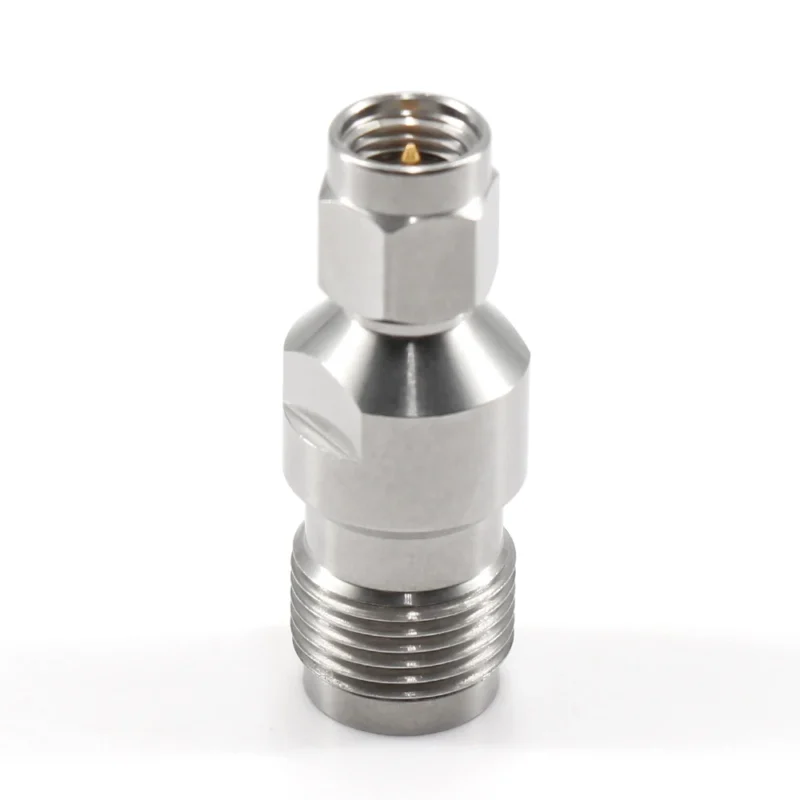
Connector placement should follow the mechanical architecture of the equipment.
If one side is repeatedly accessed in the field, exposed to vibration, or connected to a heavier external feeder, it may be sensible to keep the larger threaded TNC interface on that side.
The compact SMA interface can then remain inside the equipment or pass through a smaller panel where space is restricted.
One possible architecture is:
External TNC → flexible cable → internal SMA
Another is:
Internal TNC → flexible cable → SMA bulkhead
They use similar components, but the mechanical responsibilities are different.
Before choosing the layout, ask:
- Which side is exposed to repeated mating?
- Which panel has less available space?
- Which equipment port would be more expensive to repair?
- Where does vibration enter the system?
- Does the external connection require environmental sealing?
TNC/SMA Port Placement Decision Tree
These questions help determine whether the assembly should use TNC externally, SMA externally, or a dedicated bulkhead transition.
How should vibration change the cable and strain-relief design?
A threaded connector does not remove the need for cable support.
TNC retention can help keep the mating interface secure, but vibration can still travel through the cable body and into the termination. On the opposite end, that movement may be transferred to a much smaller SMA connector.
The risk increases with:
- Cable stiffness
- Cable weight
- Distance to the first clamp
- Continuous vibration
- Frequent service movement
- Weak SMA panel or PCB support
A larger cable such as RG58 or LMR240-class coax should normally be supported before its weight and bending moment reach the SMA termination.
Define the mechanical details in the drawing:
- No-bend distance behind the connector
- First clamp position
- Minimum bend radius
- Service loop
- Connector boot length
- Cable exit direction
A simple risk score can make this easier to review before production.
| Factor | 0 | 1 | 2 |
| Cable stiffness | Low | Medium | High |
| Cable weight | Low | Medium | High |
| Vibration | None | Moderate | Continuous |
| SMA support | Strong | Moderate | Weak |
| First clamp | Near | Medium distance | None |
| Service movement | Rare | Periodic | Frequent |
Cross-Interface Port Stress Score
A higher combined score should trigger a mechanical review rather than simply approving the drawing.
Possible corrections include adding a clamp, introducing a short flexible RG316 transition, moving the mating point to a bulkhead, or eliminating an unnecessary rigid adapter stack.
The cable should carry RF energy.
It should not become the structural member holding the SMA connector in place.
Choose straight or right-angle ends from the installed geometry
A right-angle connector should solve a routing problem, not create a new one.
On the TNC side, a straight connector is usually easier to handle when there is enough axial clearance for mating and service. It also keeps the cable exit direction predictable.
Typical locations include:
- Outdoor antenna connections
- Rack rear panels
- Open test setups
- Equipment with enough wrench and hand clearance
The SMA end is often where a right-angle version becomes more useful.
If the cable must turn immediately behind a compact receiver, PCB enclosure, or instrument port, a right-angle SMA can reduce the need for a sharp bend in the coax.
This is especially useful where the cable would otherwise be forced against a wall or neighboring connector.
A right-angle TNC requires more caution. The connector body is larger, so check side clearance, coupling access, cable exit direction, and interference with nearby hardware before freezing the drawing.
| End Combination | Main Advantage | Main Risk | Typical Fit |
| Straight TNC / Straight SMA | Simple assembly | Needs axial space | Open routing |
| Straight TNC / RA SMA | Protects compact SMA route | Orientation must be controlled | Enclosure or module |
| RA TNC / Straight SMA | Redirects larger end | Larger elbow clearance | Special panel layouts |
| RA TNC / RA SMA | Maximum routing control | Highest orientation complexity | Tight custom assemblies |
Straight/Right-Angle Architecture Matrix
Do not select both ends as right-angle parts just because space is limited. Two fixed elbows can make installation harder if their rotational orientation is not defined on the drawing.
How should outdoor sealing be specified?
A threaded TNC interface should not be treated as automatically waterproof.
The coupling structure improves mechanical retention, but environmental sealing depends on the actual connector design and the finished installation.
Separate the sealing problem into different zones:
- Connector mating interface
- Connector-to-cable termination
- Heat-shrink or boot area
- Panel interface
- SMA-side enclosure
- Unmated connector condition
If an IP rating is required, specify the required condition.
For example:
IP requirement applies to the complete assembly when fully mated and installed through the panel.
That is much clearer than writing:
Waterproof TNC to SMA cable.
Material selection also needs to match the environment. Check exposure to UV, moisture, oils, chemicals, temperature cycling, and repeated outdoor flexing.
The RF connector installation and waterproofing guide can be used for the broader installation process. The cable RFQ should still state exactly which portions of the assembly are expected to remain sealed.
Verify the full assembly instead of testing connectors separately
A correct TNC connector and a correct SMA connector do not automatically produce a correct cable assembly.
Start with workmanship inspection.
Check:
- Connector identity
- Cable part number
- Center contact condition
- Thread damage
- Ferrule position
- Heat-shrink condition
- Cable jacket damage
Then run basic electrical checks before RF testing:
- Center conductor continuity
- Shield continuity
- Center-to-shield isolation
- Movement-sensitive continuity
A continuity test can find an open or short. It cannot confirm acceptable high-frequency behavior.
For RF-critical assemblies, sweep the complete application band and review S21, S11, and S22.
The important test object is the finished cable, not the individual connector datasheet.
Compare free and installed cable response
A useful first-article check is to test the same assembly in more than one mechanical state.
Suggested states:
- Cable free and straight
- Normal installed bend
- Cable clamped
- Enclosure closed
- After connector remating
Installed-State RF Delta Test
If the response changes significantly after routing, the problem may not be the connector specification alone.
Cable stress, bend geometry, clamp location, or termination quality may be contributing.
How should a supplier-ready RFQ describe the assembly?
A good RFQ should let two suppliers quote the same part.
Start with both interfaces, then define the cable.
A useful description looks like:
TNC Male to SMA Female, RG58, 1 m, 50 Ω
A weak description looks like:
TNC-SMA Cable
The drawing or RFQ should also define the length datum. Otherwise one supplier may measure overall length while another measures mating-plane to mating-plane.
Specify:
- TNC interface
- SMA interface
- Cable family
- Impedance
- Finished length
- Length tolerance
- Length datum
- Frequency range
- Maximum insertion loss
- Return loss or VSWR target
- Straight or right-angle orientation
- Bend requirement
- Strain relief
- Environmental requirement
- Test documentation
- Prototype quantity
- Production quantity
TNC-to-SMA Cable RFQ Form
A better RFQ reduces substitution risk before production starts.
It also gives incoming inspection something measurable to compare against.
Release first articles and production lots with defined acceptance rules
Do not approve only the first sample and assume the production lot will remain identical.
Freeze the approved BOM after first-article acceptance.
Record:
- Connector part numbers
- Cable part number
- Length
- Termination process
- Heat-shrink material
- Label
- Drawing revision
Routine visual checks can cover obvious errors such as connector identity, damaged threads, wrong cable, jacket damage, and incorrect labeling.
Electrical continuity can be checked more broadly.
RF and mechanical tests can then follow a risk-based sampling plan based on the application and production history.
| Characteristic | Method | Sampling | Limit | Failure Action |
| Connector ends | Visual | 100% | Drawing | Quarantine |
| Cable P/N | Visual | 100% | BOM | Hold |
| Finished length | Measurement | Sample | Drawing | Sort |
| Continuity | Electrical | 100% | Pass | Rework |
| Pull retention | Fixture | Risk-based | Project limit | Expand sample |
| S21 | VNA | Risk-based | RFQ | Hold |
| S11 / S22 | VNA | Risk-based | RFQ | Investigate |
| Installed fit | Golden fixture | First article | Pass | Stop release |
TNC-to-SMA Lot Acceptance Matrix
This is especially useful when assemblies are sourced repeatedly. A sample that passed six months ago is not a substitute for a controlled production specification.
Which design mistakes turn a simple cable into a field failure?
Several mistakes appear simple on the drawing and expensive in the field.
Hanging a heavy feeder directly from the SMA end
A larger coaxial cable can place bending force on a compact SMA connector.
Add a clamp, support point, or flexible transition before the port.
Using a rigid adapter where a short cable should isolate movement
Rigid adapters are useful when interfaces align properly.
They become less attractive when port offset, vibration, or cable leverage must be absorbed. For aligned installations, the existing SMA to TNC adapter guide covers the rigid-adapter option separately.
Selecting cable length before confirming the routed path
A length chosen from straight-line distance can become too short after bend radius, service loop, and clamp locations are added.
Measure the installed route.
Assuming connector frequency determines assembly frequency
The complete path includes:
- TNC connector
- SMA connector
- Coax
- Terminations
- Bends
- Manufacturing variation
The lowest-performing element can set the real limit.
Testing the cable straight and installing it sharply bent
A straight bench result is not always representative of the installed assembly.
For critical applications, validate the final routing during first-article testing.
FAQ
How long can a TNC to SMA cable be before the coax should be upgraded?
There is no fixed maximum length. Calculate the allowable cable loss from the operating frequency and system loss budget. A short assembly may favor RG316 for flexibility, while a longer run may justify RG58 or a lower-loss cable family. The correct limit should come from the finished assembly requirement rather than connector type alone.
Should the TNC or SMA connector be placed on the externally accessible side?
It depends on the mechanical role of the connection. TNC is often useful where threaded retention, field handling, or a larger external feeder is involved. SMA is more compact and may fit better inside equipment or on a space-limited panel. Service access, vibration, repair cost, and panel space should decide the layout.
Can a heavy TNC feeder damage the SMA end of the assembly?
Yes. A stiff or heavy cable can transfer bending moment and vibration into the smaller SMA port if it is unsupported. Add strain relief, a clamp, a service loop, or a short flexible transition so the equipment connector is not carrying the cable mechanically.
Is a threaded TNC connection automatically waterproof?
No. Threaded coupling improves mechanical retention, but waterproofing depends on the connector seal, cable termination, panel gasket, boot, and the final mated condition. Any required IP rating should be specified and verified for the complete installed assembly.
Does using a TNC connector mean the complete cable can operate to 11 GHz?
Not automatically. The TNC interface may support that range under the relevant standard, but the complete assembly is also limited by the SMA connector, coaxial cable, termination quality, and routing. Finished-cable S-parameter testing is the safer basis for defining the usable band.
When should RG316 be used instead of RG58?
RG316 is useful when the assembly is short, space is tight, or the SMA side needs a lighter and more flexible cable. RG58 may be more practical when the route is longer and additional diameter is acceptable. Compare attenuation and mechanical routing together rather than selecting by cable size alone.
Should a TNC-to-SMA cable be VNA-tested after it is bent into its final route?
For RF-critical or higher-frequency applications, first-article testing in the installed routing is useful. Bending, clamping, connector stress, and enclosure geometry can change S21 and return loss. Testing only the cable in a straight free state may miss an installation-related problem.
Final buying guidance
A TNC to SMA cable should be specified as a complete RF and mechanical assembly, not as two connector names joined by coax.
Before ordering, confirm:
- Both mating interfaces
- Standard or reverse polarity
- 50-ohm requirement
- Cable family
- Finished routed length
- Operating frequency
- Maximum acceptable insertion loss
- Straight or right-angle geometry
- Strain-relief position
- Environmental exposure
- First-article and production test requirements
The connector ends may be the most visible part of the assembly, but the cable length, routing, termination, and mechanical support often decide whether the finished part works reliably in the equipment.
If the assembly will operate near its frequency or loss limit, send the operating band, cable type, routed length, connector configuration, and inspection target with the RFQ.
That gives the supplier something measurable to build and gives the buyer something measurable to accep
