
A PL259 plug can screw onto an SO239 socket perfectly and still leave you with a bad RF connection.
That sounds contradictory until the cable is put on a radio and the SWR jumps. On the bench, the assembly may even pass a continuity check. The center conductor is connected, the shield is connected, and nothing is shorted. Electrically, at DC, everything looks fine.
RF is less forgiving.
We have seen the same purchasing mistake in different forms: the buyer confirms “PL259,” but not the cable size; a cable shop installs a connector that physically accepts the coax but does not grip the braid correctly; or an older radio uses an SO239 port and the replacement cable is ordered only from a product photo. The parts mate. The system does not behave as expected.
That is why a UHF connector should be treated as part of the RF path, not as a simple threaded metal fitting.
For most amateur radio, CB radio, and two-way radio installations, the practical selection path starts with four things: the equipment port, the mating connector, the coaxial cable, and the operating band. If any one of those is guessed, the finished assembly may still “fit” while creating unnecessary mismatch or mechanical trouble.
Which UHF Connector Belongs at Each End of the RF Link?
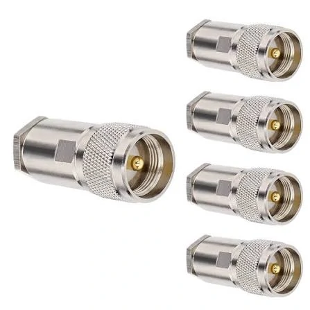
N Type male coaxial cable connectors for RF communication, antenna and test applications, commonly considered when a more controlled RF interface is required than traditional UHF connectors
The easiest place to make a mistake is often the first line of the purchase request.
“Need UHF cable, both ends.”
That is not enough information for production.
A common fixed-radio arrangement has an SO239 receptacle on the transceiver and another SO239 connection at the antenna side. In that case, a PL259 plug is normally fitted to each end of the coax. Simple enough.
But plenty of real systems do not follow that layout. A power amplifier may use an N-Type connector. A handheld radio may use SMA. A test instrument may use BNC. Some antennas leave the factory with a permanently attached coax lead rather than a chassis receptacle.
Identify the Radio Port Before Selecting a Cable Connector
Look at the actual radio port before approving the cable BOM.
An SO239 receptacle normally has external threads around the interface and a female center contact inside. The mating PL259 plug has the coupling nut around the body and a male center pin.
That distinction sounds basic, but it prevents a surprising number of sourcing errors.
Product listings are not always consistent with terminology either. Some suppliers describe the interface simply as “UHF female,” “UHF socket,” or “radio antenna connector.” Those names may point to the same general family, but purchasing should still be based on the physical interface and drawing rather than the listing title.
If the equipment is already in use, a front-facing photo of the connector is useful. A dimensional drawing is better.
For a repair job, also check whether the connector is mounted directly through the equipment panel or attached by a short internal pigtail. That detail can affect how much mechanical load the external coax should be allowed to place on the port.
Separate the Cable Plug From the Equipment Receptacle
In the traditional UHF connector system, PL259 and SO239 usually appear as a pair.
The PL259 is commonly the cable-side male plug. The SO239 is commonly the female receptacle mounted to a radio, antenna, enclosure, or adapter.
“Commonly” matters here.
Connector gender describes the mating interface. It does not guarantee where the connector must be installed. SO239 interfaces can appear in adapters and cable accessories, while PL259 variants differ in rear construction even though the front end looks familiar.
That rear construction is where many purchasing problems begin.
Two PL259 connectors can have the same mating face but completely different cable-entry diameters. One may be intended for a larger coax. Another may use a reducer. A modern crimp version may require a specific ferrule size and crimp die.
The front threads do not tell you any of that.
For detailed PL259 construction and termination considerations, TEJTE’s PL259 cable plug guide can be used as the interface-specific reference. In this article, the PL259 is treated as one part of the full UHF cable system rather than as a standalone product.
Distinguish Direct Antenna Connections From Coax Feed Lines
Cable length changes the problem.
A short jumper behind a radio and a 20-meter antenna feed line may both use PL259 plugs, yet the buying decision is not the same.
With a short jumper, flexibility may matter more than absolute cable loss. A smaller coax can be easier to route around equipment, through a console, or behind a rack.
Longer antenna runs shift attention toward attenuation and mechanical support. At that point, a larger cable may make more sense, but it also becomes heavier and less forgiving around tight bends.
This is where the connector and cable stop being separate purchasing items.
A heavy RG213-style feed line hanging directly from an equipment-mounted SO239 can put real bending force on the radio port. Even when the electrical connection is fine, poor strain relief can loosen the panel connector over time.
For procurement, this means cable diameter and routing should be discussed before the assembly drawing is frozen.
Confirm the Entire RF Path Before Ordering Components
A normal UHF feed line might look like this:
Radio SO239 → PL259 → 50Ω Coax → PL259 → Antenna-Side SO239
That is a useful starting point, not a universal rule.
If an adapter is added somewhere in the path, record it. If the antenna uses another connector family, record that too. If the cable changes halfway through the system, that also belongs in the RF path description.
The more accurately the path is documented at the quotation stage, the less likely it is that production ends up solving compatibility problems with extra adapters.
Those adapters may make the system connect mechanically, but they also add another interface that can loosen, corrode, or contribute to mismatch.
How Do PL259 and SO239 Interfaces Mate Correctly?
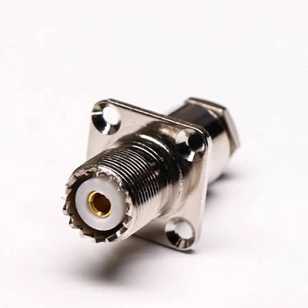
SO239 UHF female panel mount connector featuring a four-hole flange and threaded RF interface for radios, antennas, enclosures and communication equipment.
Correct mating is not only about getting the threads started.
A PL259 that has been dropped, overheated during soldering, or repeatedly forced onto a damaged socket may still screw into place. That does not mean the center contact is making good RF contact.
Identify the PL259 Plug by Its Coupling Structure
The typical PL259 plug uses a rotating threaded coupling section around the male center pin. During mating, that outer section engages the threads of the SO239 receptacle while the center pin enters the female contact.
On a new connector, the process should feel straightforward. If the plug needs to be forced, stop.
Cross-threading is easy to create and difficult to fix cleanly. Dirt, damaged threads, a tilted center pin, or a deformed socket can all increase resistance during mating.
The cable should also not be used as a handle for tightening the connector. Twisting the entire coax can transfer stress into the termination, especially on assemblies with a soldered center conductor or braid connection.
Check the SO239 Receptacle and Center Contact
The SO239 deserves the same inspection.
Look inside the center contact. If it appears spread, corroded, contaminated, or mechanically loose, simply replacing the cable may not solve the problem.
Panel movement matters too.
An SO239 mounted on thin sheet metal can gradually work loose if a heavy coax cable is left unsupported. In a mobile installation, vibration adds another variable. The RF problem may appear intermittent: the radio tests normally on the bench, then SWR shifts when the cable is moved.
That kind of fault is easy to misdiagnose as an antenna problem.
For equipment-side details, the SO239 connector guide is the better place to examine panel construction and receptacle selection in depth.
Avoid Confusing “UHF” With a Guaranteed Frequency Range
The name causes unnecessary confusion.
“UHF connector” is a historical connector-family name. It does not mean every PL259 and SO239 assembly is automatically suitable across the full modern UHF radio band.
Traditional UHF interfaces are not precision constant-impedance connectors in the same sense as SMA or N-Type.
At lower frequencies, the mismatch introduced by the interface may be acceptable for many radio systems. As frequency increases, the connector geometry, cable transition, assembly quality, and total RF path deserve more attention.
So a buyer should never approve a PL259 assembly only because the application frequency happens to fall inside something called “UHF.”
The actual operating band still belongs on the drawing or purchase specification.
Which Coax Cable Fits the Selected PL259 Connector?
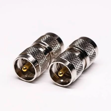
Metal UHF coaxial adapter connectors for joining threaded RF interfaces in radio, antenna, test and coaxial cable systems.
The front of the connector gets most of the attention. The rear is where compatibility is usually decided.
A PL259 plug may mate with the radio perfectly and still be the wrong part for the coax. Cable outside diameter, center conductor size, dielectric diameter, braid construction, and the connector’s rear entry all affect whether the termination can be assembled correctly.
This is why “PL259 for 50Ω cable” is not a complete purchasing description.
Compare RG58, RG8X, RG213, and LMR400-Type Cable Construction
RG58, RG8X, RG213, and LMR400-type cables can all appear in radio antenna systems, but they are not interchangeable at the connector rear body.
RG58 is relatively small and flexible. It can work well for short jumpers, mobile installations, and routing through limited space. RG8X is also popular where users want a compromise between flexibility and lower attenuation.
RG213 is much larger. It is commonly selected for longer antenna feed lines where cable loss matters more than compact routing. LMR400-type cables fall into a similar lower-loss application category, although their internal construction is different from traditional RG213.
That difference matters at termination.
| Cable family | Practical reason for selection | PL259 detail to verify | Common sourcing risk |
| RG58 | Flexible, compact routing | Rear entry or approved reducer | Connector body too large for cable |
| RG8X | Moderate-size radio feed line | Exact cable dimensions | Assuming all “mini-8” cable is identical |
| RG213 | Larger antenna feed line | Larger cable entry and shield termination | Poor braid contact during assembly |
| RG8 | Larger RF feeder | Exact cable variant | Ordering only by RG name |
| LMR400-type | Lower-loss longer runs | Connector made for actual cable construction | Using an RG213 connector because the OD looks similar |
The table is useful for initial selection, but it should not replace the connector drawing.
Two cables can have a similar outside diameter and still need different center contacts or shield termination geometry.
Check Cable Diameter Against the Connector Rear Body
The quickest inspection is usually the cable entry.
If the coax is too small for the connector body, the assembly may have poor mechanical retention unless the design uses the correct reducer. If the cable is too large, installers sometimes remove too much jacket, trim braid excessively, or force the cable into a body that was not intended for it.
None of those are good production solutions.
The drawing should identify the approved cable or at least provide the dimensions needed to confirm compatibility.
For custom assemblies, it is better to freeze the actual cable part number rather than write only “RG58” or “RG213” in the BOM. Different manufacturers may use slightly different constructions under the same general cable family.
Verify Center Contact and Shield Termination Compatibility
The outside diameter is only the first check.
The center conductor must also fit the center contact correctly. A solid conductor, stranded conductor, or different conductor diameter can change how the termination is soldered or crimped.
The shield deserves the same attention.
A connector may appear mechanically secure while the braid has poor contact with the outer body. That kind of defect can be difficult to find with a casual visual inspection. The assembly may still show continuity, yet RF behavior can become unstable when the cable is moved.
For repeat production, the operator should know exactly how much jacket and dielectric to strip. “Trim until it fits” is not a controlled assembly method.
Use Cable-Specific Reducers Only Where Approved
Some traditional PL259 installations use reducers for smaller coaxial cables.
A reducer is not simply a filler sleeve.
Its dimensions must allow the cable to sit correctly inside the connector while maintaining proper shield contact and strain support. A reducer that accepts the cable physically can still be wrong if the finished braid termination or center conductor position is incorrect.
For purchasing, specify the connector and reducer together whenever the design depends on both.
When Should You Choose Solder, Crimp, or Clamp Termination?
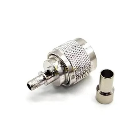
PL259 UHF male coaxial connector with threaded coupling structure and cable termination components for RF cable assemblies, radios and antenna feed lines.
There is no single “best” PL259 termination method.
The better question is which method matches the connector design, cable construction, available tooling, and production volume.
Evaluate Solder Termination for the Approved Cable Design
Traditional solder-style PL259 connectors remain common.
They can produce a sound connection when the cable preparation and soldering process are controlled, but workmanship matters. Too little heat may leave an incomplete joint. Too much heat can soften or deform dielectric material near the termination.
Excess solder creates another problem. It can interfere with assembly or allow solder to wick farther into stranded conductors than intended, producing a stiff section directly behind the connector.
That section is more vulnerable when the cable is repeatedly bent.
A good solder joint should not depend on covering the area with more solder than necessary.
Evaluate Crimp Termination for Repeatable Cable Assembly
Crimp designs are attractive for production because they can be more repeatable once the connector, cable, ferrule, and tooling are fixed.
The important phrase is once they are fixed.
A crimp connector should not be qualified using one cable and then moved to another cable simply because both are sold under a similar RG designation.
Ferrule diameter and crimp die size matter. An oversized die may produce weak cable retention. An undersized die can deform the ferrule, damage the cable, or create an assembly that passes visual inspection but has inconsistent shield contact.
Production records should identify the crimp tool or die set when repeatability matters.
Use Clamp Termination Where the Connector Design Requires It
Clamp-style termination uses mechanical compression rather than relying entirely on solder or a separate crimp ferrule.
It can be useful where the connector was designed around that method, but assembly order becomes important. Braid preparation, washer orientation, clamping surfaces, and tightening sequence all need to follow the connector drawing.
Mixing instructions from another PL259 design is a common workshop mistake.
The mating face may be the same. The cable preparation may not be.
Inspect the Completed Cable Before RF Testing
Before connecting the assembly to a radio, check the basics.
The center conductor should be continuous from end to end. The shield should also show electrical continuity. There should be no unintended short between center and shield.
Then move the cable gently near both connectors while repeating the check. An intermittent termination sometimes appears only when the cable is flexed.
Mechanical retention should also be inspected. A connector that rotates on the cable or slides under light pulling force needs investigation before RF testing.
How Should You Evaluate UHF Connector Frequency and Impedance?
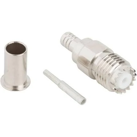
SO239 UHF female crimp coax connector showing the connector body, center contact and crimp ferrule used for coaxial cable termination and RF cable assembly.
A UHF connector should not be evaluated from its name.
Traditional PL259/SO239 geometry is not a precision constant-impedance interface in the same way as SMA or N-Type. That does not make it unusable. It means performance should be judged against the actual radio system.
At lower frequencies, the discontinuity may have little practical effect. As frequency rises, reflections from the connector transition can become more noticeable.
Cable loss also increases with frequency, so the connector should not be blamed automatically when a long feed line measures poorly.
Measure the Complete Assembly, Not Just the Connector
If SWR or return loss matters, test the finished cable assembly at the intended operating band.
A VNA or suitable antenna analyzer can reveal behavior that a multimeter cannot see.
This is especially useful when the assembly includes long coax, multiple adapters, or a cable type that has not previously been qualified with the selected PL259 design.
If performance becomes marginal near the upper operating band, moving to a more controlled RF interface such as N-Type may be worth evaluating.
The decision should come from the system requirement and measured results—not from the historical “UHF” label alone.
How Should You Route and Protect a UHF Coax Connection?
A cable assembly can test correctly on the bench and still develop trouble after installation.
The reason is often mechanical rather than electrical.
A heavy coax such as RG213 or an LMR400-type cable can place noticeable load on an SO239 panel connector. If the cable is allowed to hang directly from the radio, vibration and repeated movement may gradually loosen the receptacle or stress the termination behind it.
Support the cable before that load reaches the equipment.
For rack systems, vehicle installations, and outdoor antenna feeds, strain relief should be planned as part of the RF path rather than added after the connector begins moving.
Keep Cable Bends Away From the Connector Body
The tightest bend should not occur immediately behind the PL259.
A sharp bend near the connector concentrates stress at the termination. With soldered designs, repeated flexing may eventually affect the conductor near the solder joint. With crimped assemblies, excessive side loading can work against the ferrule and jacket retention.
The correct minimum bend radius depends on the actual cable construction.
Do not assume that two cables with similar outside diameters tolerate the same routing.
Protect Outdoor Connections From Moisture
A normal PL259/SO239 connection should not automatically be treated as weatherproof.
Outdoor installations need a separate protection plan.
That may include suitable sealing tape, weather-resistant overwrap, a drip loop, and mechanical support that prevents water from collecting around the connector.
The sealing material should also be compatible with the cable jacket and installation environment.
Corrosion can develop gradually, and the first symptom may be increasing SWR rather than a complete open circuit.
How Can You Diagnose High SWR After Installing UHF Connectors?
High SWR after installation does not prove that the connector is defective.
The antenna may be mistuned. The coax may be damaged. A shield connection may be incomplete. An adapter could be loose. The problem may even appear only when the cable is moved.
Start by separating the RF path into sections.
Separate Antenna Problems From Feed-Line Problems
If possible, replace the antenna with a suitable known load and test the feed line again using an antenna analyzer or VNA.
If the cable assembly behaves normally with the load, the antenna side deserves closer attention.
If the result remains poor, inspect the feed line and connectors.
This approach is more useful than immediately cutting off both PL259 plugs and replacing them.
Check Center-to-Shield Shorts and Intermittent Connections
A multimeter is useful for the first inspection.
Check center conductor continuity from one end to the other. Repeat the same test for the shield. Then confirm that there is no unintended short between the center conductor and outer conductor.
Move the cable gently near each connector while watching the measurement.
An assembly that changes continuity during movement probably has a termination problem, even if it looked correct while lying still.
But continuity is not an RF acceptance test.
A cable can pass every basic resistance check and still have poor return loss or excessive insertion loss at the operating frequency.
How Can You Qualify a Complete UHF Cable Assembly?
A useful qualification process checks more than whether PL259 and SO239 can screw together.
The connector, cable, termination, mechanical retention, and RF behavior should be treated as one assembly.
For production work, a compact acceptance matrix is easier to use than a long description.
| Inspection item | What should be confirmed |
| Interface | Correct PL259/SO239 mating |
| Cable | Exact approved cable part number |
| Cable dimensions | Match connector drawing |
| Center contact | Correct position and secure attachment |
| Shield | Full electrical and mechanical contact |
| Isolation | No center-to-shield short |
| Retention | Meets approved pull or handling requirement |
| RF test | Meets project SWR or return-loss limit |
| Environment | Suitable sealing and cable support |
| Documentation | Approved drawing and test record |
This table is not an industry certification standard. It is a practical release tool for sourcing and production.
Estimate the Cable Assembly Loss Before Testing
This is only an engineering estimate.
Reflections, adapter stacks, poor terminations, and the measurement reference plane can change the actual result.
The purpose of the formula is not to replace testing. It helps buyers recognize when the cable itself may become the larger loss contributor.
Use a Release Rule for Production Assemblies
If one of those items fails, the assembly should not be approved simply because continuity is normal.
That matters especially when a first sample is being converted into a repeat production order.
How Should Buyers Specify a UHF Connector Assembly for Production?
The safest purchase request is specific enough that the supplier does not need to guess.
Add environmental requirements when needed.
Outdoor use, temperature exposure, vibration, cable support, labeling, and packaging can all matter in production even though they do not change the mating interface.
Before quantity production, confirm the drawing and first article.
Freeze the approved connector, cable, termination process, and tooling. If one of those changes later, decide whether requalification is required.
That is more reliable than approving substitutions only because the replacement still carries the PL259 name.
FAQ
Can a PL259 fit an SO239 and still cause high SWR?
Yes. Correct mechanical mating does not prove good RF performance. Poor shield termination, damaged contacts, cable defects, or antenna mismatch can still produce high SWR.
Can one PL259 connector be used for both RG58 and RG213?
Not automatically. The rear body, reducer, center contact, and shield termination must match the actual cable construction.
Does “UHF connector” mean it works across the entire UHF band?
No. The name is historical. The actual connector, cable assembly, operating frequency, and measured RF performance should be checked.
Can an outdoor PL259/SO239 joint be left unsealed?
It should not automatically be considered weatherproof. Outdoor installations normally need suitable moisture protection and cable support.
Why can a cable pass continuity but fail RF testing?
Continuity only confirms basic electrical connection. It does not measure impedance discontinuity, return loss, SWR, or insertion loss.