
A cable can screw onto the radio and still be the wrong part.
That is the common problem with a PL259 connector. The front mating side looks familiar, the threaded coupling feels secure, and a quick continuity test may pass. But the actual selection work starts behind the connector: the installed SO-239 port, the coaxial cable diameter, the center conductor, the shield structure, and the termination method all decide whether the finished cable is usable or just mechanically attached.
For CB radio, HF amateur radio, antenna tuners, older VHF equipment, and some bench fixtures, the PL-259/SO-239 pair is still a practical legacy interface. The mistake is treating every catalog name as interchangeable. “PL259,” “PL 259 connector,” “UHF male connector,” and “UHF cable connector” may point to the same general family, but they do not automatically define the cable fit, reducer, ferrule, body style, or RF acceptance requirement.
How do PL-259, SO-239, and UHF connector names map to one mating pair?
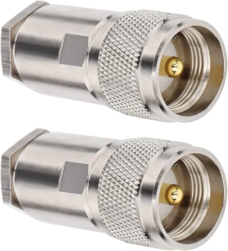
PL-259 is normally the cable-side plug. In many catalogs it is also described as a UHF male connector, especially in radio and antenna cable listings. The installed equipment side is usually SO-239, also called a UHF female connector or UHF jack.
The practical mating path is simple:
Coax cable -> PL-259 plug -> SO-239 equipment receptacle
That sounds obvious, but it prevents a lot of ordering mistakes. A buyer asking for a “UHF connector” may receive a PL-259 plug, an SO-239 panel jack, an inline adapter, or a bulkhead part, depending on the supplier’s catalog language. The family name alone is not enough for a production BOM.
Treat “UHF connector” as the connector family. Do not treat it as a gender description. PL-259 and SO-239 both belong to the UHF connector family, but they sit on opposite sides of the mating pair. The same rule applies when a customer says “UHF coax connector.” Ask whether they need the cable plug or the panel/device receptacle before confirming the part.
Here is a cleaner naming decoder for procurement and customer service teams:
| Search / Catalog Name | Connector Role | Typical Location | Mates With | Buyer Check |
| PL-259 | Plug | Cable end | SO-239 | Confirm cable size and termination |
| SO-239 | Jack / receptacle | Radio, chassis, panel | PL-259 | Confirm panel or device mounting |
| UHF male | Usually PL-259 plug | Cable end | UHF female | Verify front geometry and cable fit |
| UHF female | Usually SO-239 jack | Panel, device, adapter | UHF male | Verify mounting style and rear connection |
A useful RFQ should therefore say “PL-259 cable plug for RG58” or “SO-239 4-hole flange panel jack,” not just “UHF connector.” That one extra line removes most of the ambiguity before samples are made.
Which installed radio port should you identify before ordering the plug?
Start from the equipment, not from the cable listing.
If the radio, antenna tuner, amplifier, or test fixture already has an SO-239 connector, the cable side usually needs a PL-259 plug. But the buyer should still inspect the installed port before placing an order. Some older equipment has worn threads, recessed connector positions, limited wrench space, or center sockets that no longer grip correctly. A new cable cannot solve all of those problems.
Check these items before selecting the plug:
- Equipment model
- Port label
- Connector family
- Jack or plug
- Thread condition
- Center contact condition
- Chassis recess or panel clearance
- Intended operating band
- Existing mating cable, if available
Do not rely only on the word “UHF” printed near the port. On radio equipment, “UHF” may refer to the operating band, not the connector family. A device can operate in a UHF radio band and still use N-Type, BNC, SMA, TNC, or another RF interface. The connector must be confirmed by the port geometry, the equipment drawing, the manual, or a known-good mating cable.
This record is especially useful when the customer sends only a product photo. It gives sales, purchasing, and engineering the same reference point before choosing the connector or quoting a cable assembly.
How do you match a PL259 connector to the actual coax cable?
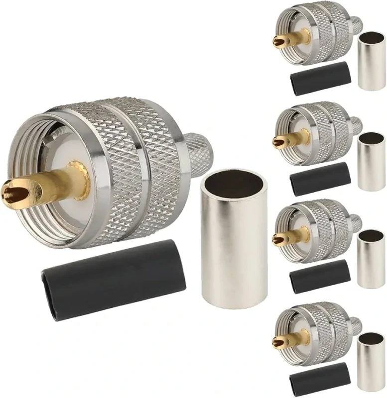
The front of the connector mates with the radio. The rear of the connector decides whether it fits the cable.
That is where many PL-259 mistakes happen. A PL259 connector RG58 configuration is not automatically the same as a PL-259 for larger radio coax. Even if both cables are 50 ohm, the jacket OD, braid diameter, dielectric diameter, and center conductor size may be different. A connector made for one cable group may not grip, solder, or crimp correctly on another.
Start with the cable construction:
- Jacket outside diameter
- Shield braid diameter
- Dielectric outside diameter
- Center conductor diameter
- Solid or stranded center conductor
- Reducer or sleeve requirement
- Rear bore of the connector body
- Ferrule size, if crimped
- Solder window or solder-hole design, if soldered
RG58-class cable is a common source of confusion because it is widely used and often sold with PL-259 plugs. The correct question is not “Does this PL-259 fit radio cable?” The better question is: “Is this PL-259 body, reducer, ferrule, and center contact designed for this exact RG58 cable construction?”
Small flexible coax, RG58-class cable, and larger feeder cable should stay on separate termination paths. A loose rear fit can reduce pull strength. Too much heat during soldering can move the dielectric. A mismatched ferrule can make the shield contact inconsistent. The finished cable may still pass a meter test, then show unstable RF behavior after bending or repeated mating.
This table looks basic, but it catches the real purchasing risk. The PL-259 name only defines the mating family. It does not prove that the rear hardware matches the coax cable.
For a custom RF cable assembly, write the BOM in a way the workshop can actually build from:
PL-259 cable plug, for RG58 coax, matched reducer or ferrule, defined termination method, 50 ohm radio cable assembly, inspection by continuity and project RF requirement.
That is much safer than writing “UHF cable connector” and leaving the rest to interpretation.
Which termination method fits the production or field-repair job?
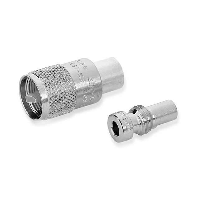
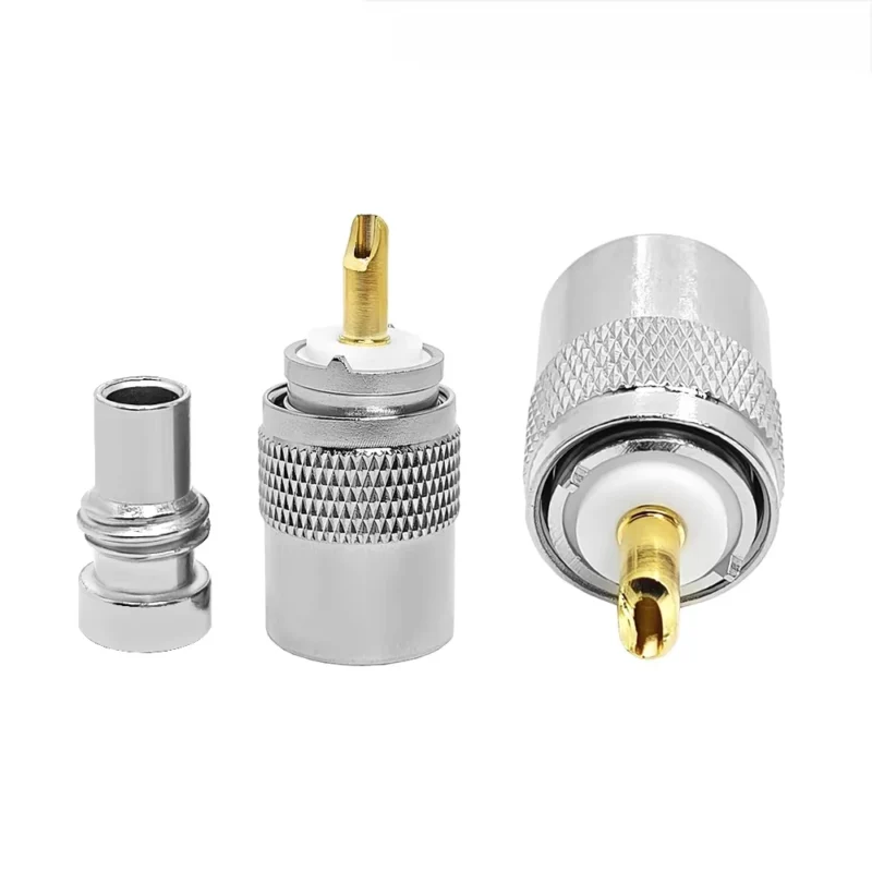
Disassembled PL259 compression connector showing the threaded connector body and rear termination component used for coaxial cable installation.
The connector style is only half of the decision. The termination method decides how repeatable the cable assembly will be after real handling, bending, and mating cycles.
For PL-259, the common routes are crimp, solder, and compression. They should not be treated as casual substitutes. A PL259 crimp connector depends on the correct ferrule size, crimp die, cable braid preparation, and center contact fit. A PL259 solder connector depends more heavily on operator control, heat input, solder wetting, and the way the shield is brought into contact with the body. A PL259 compression connector should only be used with a connector system designed for compression, not as a shortcut for a crimp or solder design.
Crimp is usually preferred when production speed and repeatability matter. It gives the workshop a more controlled process, provided the cable, ferrule, tool, and die are locked down. The risk appears when a buyer changes cable source or cable OD without updating the connector and crimp tool.
Solder still has a place, especially in field repair, legacy radio work, and connector styles built around soldering. The weak point is heat. Too much heat can soften or shift the dielectric, disturb the center conductor position, or leave the shield joint inconsistent. A cable may look acceptable from the outside while the internal geometry has already moved.
Compression is different again. It is clean and fast when the connector and tool are designed as a matched system. It is not a universal answer for every UHF cable connector.
Use the termination route as a process decision, not a catalog preference:
| Requirement | Crimp | Solder | Compression |
| Field repair | Good if tools are available | Common for legacy repair | Limited unless system matched |
| Production speed | Strong | Slower | Strong |
| Tool dependence | High | Medium | High |
| Operator dependence | Medium | High | Medium |
| Heat exposure | Low | High | Low |
| Pull repeatability | Good with correct die | Process-dependent | Good with matched system |
| Cable-size sensitivity | High | High | High |
| Inspection difficulty | Medium | Medium to high | Medium |
| Best use | Repeatable cable assembly production | Legacy and repair work | Matched compression connector systems |
The table is not a ranking. It is a way to stop the wrong question. “Which one is better?” is too broad. The better question is: which method fits the cable, tooling, operator skill, inspection target, and production volume?
How should solder or crimp dimensions be transferred into the work instruction?
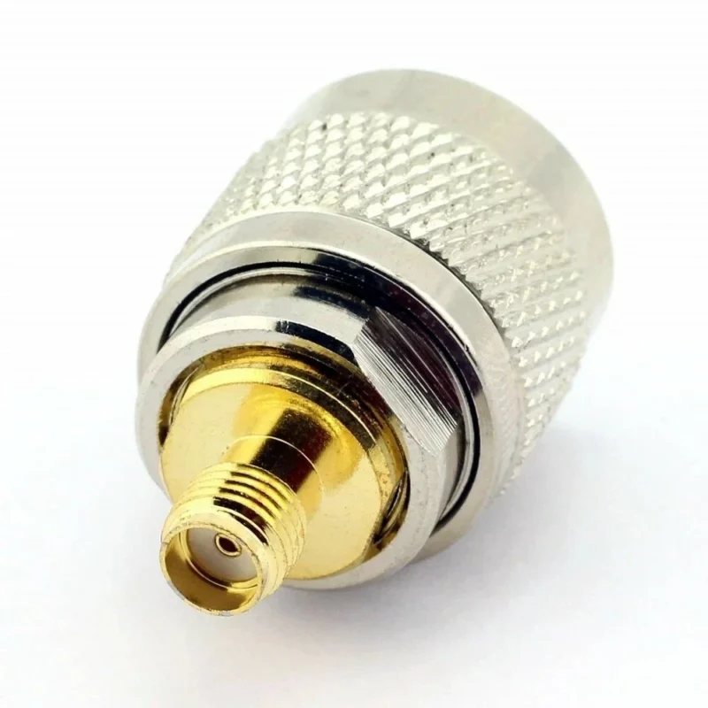
A sample can work because one technician adjusted by hand. Production needs numbers.
For a PL-259 cable assembly, cable preparation should be transferred into a work instruction from one reference end. Define jacket strip length, braid preparation, dielectric exposure, center conductor length, ferrule position, and finished connector length. Do not leave these as “same as sample” unless the sample is documented with dimensions.
The center conductor deserves special attention. If it is bent before final assembly, the finished connector may still mate, but the contact position can be off-center. If the dielectric recedes after soldering, the center conductor may move under mechanical stress. If the braid is loose or uneven, the shield contact becomes inconsistent.
Inspect the shield before it disappears under the body or ferrule. Once the connector is fully assembled, the most important workmanship area may no longer be visible.
A small cable prep record can prevent a large number of repeat mistakes:
This is especially useful when one factory is making several versions of the same radio cable. A PL259 connector RG58 assembly and a larger coax assembly may use the same front mating family, but the workstation dimensions should not be copied blindly.
Why does the name “UHF connector” create a frequency-selection trap?
The name causes trouble because it sounds more modern than the interface really is.
Today, many engineers understand the UHF radio band as 300 MHz to 3 GHz. But the UHF connector name comes from earlier radio usage. Standard PL-259/SO-239 interfaces are widely treated as low-frequency, general-purpose threaded RF connectors, not precision GHz connectors.
That is why a buyer should not write “UHF frequency capable” in an RFQ. It says almost nothing. A better requirement is the actual operating band, cable length, connector count, and test method.
The other issue is impedance. A PL-259/SO-239 interface is commonly described as non-constant impedance. That does not mean every cable will fail. It means the connector should not be judged like a controlled-impedance SMA or N-Type connector. At HF and many legacy radio frequencies, it may be completely practical. Near higher VHF or beyond, the exact part, cable assembly quality, and measured RF response matter more.
For background, manufacturer data such as UHF connector electrical and mechanical characteristics commonly describes UHF connectors as threaded, non-constant-impedance interfaces with typical low-frequency use. That is the key sourcing lesson: the name is not the rating.
A simple approval gate helps:
- Identify the exact connector part number.
- Identify the exact coax cable.
- Define the system operating band.
- Check the connector and cable manufacturer ratings.
- Measure the finished assembly if operating near the normal limit.
- Compare return loss and insertion loss against the project requirement.
- Approve, hold, or redesign.
The cable may become the bottleneck before the connector. Or the connector transition may be the weak point before the cable length becomes a problem. Testing the assembly is the only clean way to separate those two issues.
When should SO-239 be mounted as a chassis or bulkhead interface?
SO-239 is usually the fixed side of the PL-259/SO-239 pair. It belongs on the radio, panel, test fixture, antenna tuner, amplifier, or enclosure when repeated mating should be carried by a supported structure.
A UHF bulkhead connector or SO-239 panel jack is not the same thing as an inline female adapter. They may both be described as UHF female in a catalog, but their mechanical jobs are different. A panel connector must control mounting, grounding, anti-rotation, rear clearance, and cable or solder access. An inline female adapter only extends or changes the mating interface.
Before machining a panel, confirm the mounting geometry. Check hole size, flange dimensions, hole spacing, thread clearance, rear body clearance, and ground contact. A small drawing error can make the connector impossible to tighten or leave the cable exit under stress.
A panel architecture comparison is useful during design:
| Requirement | 4-Hole Flange | Bulkhead Nut | Inline Female |
| Panel support | Strong | Medium to strong | Weak |
| Anti-rotation | Strong | Depends on hardware | Weak |
| Grounding control | Good with metal panel | Good if tightened correctly | Limited |
| Serviceability | Good | Good | Good, but unsupported |
| Cable load isolation | Strong | Medium | Poor |
| Typical role | Radio chassis, fixture, equipment panel | Enclosure feedthrough | Adapter or extension |
If the cable is heavy, frequently removed, or routed outdoors, avoid leaving a long unsupported adapter stack hanging from the SO-239 port. The radio connector may survive the first installation and loosen later.
Decide when a UHF connector should give way to N-Type
Keep PL-259/SO-239 where legacy equipment compatibility is the main requirement. CB radios, HF amateur radio equipment, older antenna tuners, and many existing installations already use this interface. In that world, the simplest and most serviceable answer may be a properly matched PL-259 cable assembly.
Move toward N-Type when the RF path asks for a more controlled interface. N-Type is normally the safer direction when the system involves higher-frequency work, outdoor sealing options, lower VSWR expectations, low-loss feeder cable, or equipment where return loss matters more than legacy compatibility.
This is also where adapter stacks become suspicious. If the path becomes PL-259 to adapter to SMA to another adapter to N-Type, the design may be solving the wrong problem. Every adapter adds contact pairs, mechanical length, and one more place to loosen or reflect energy. A purpose-built cable assembly is often cleaner.
For coax selection before connector approval, the RG cable guide can help compare cable families, while a dedicated N-Type guide is better for deciding when a controlled-impedance threaded connector is the better fit.
| Requirement | PL-259 / SO-239 | N-Type |
| Legacy radio compatibility | Strong | Limited unless equipment supports it |
| HF use | Common and practical | Also possible, but often unnecessary |
| Higher-frequency precision | Limited | Stronger |
| Constant impedance interface | No, generally non-constant | Yes, in standard RF designs |
| Outdoor sealing options | Depends on version and sealing method | Common in many product lines |
| Low-loss feeder support | Possible with correct connector | Strong for larger RF cable systems |
| Existing installed base | Very strong | Strong in RF infrastructure |
| Cost and simplicity | Often simple | Usually higher specification |
The right answer is not always the newer connector. If the equipment already uses SO-239 and the application is within a practical frequency range, a well-built PL-259 cable can still be the most sensible option. If the system is drifting into precision RF, long outdoor feeder runs, or GHz-range expectations, it is time to compare N-Type before the adapter stack grows.
How should PL259 adapters be used without creating a long RF stack?
A PL259 adapter is useful when it solves one clear interface problem. It becomes risky when it turns into a chain of compromises.
One adapter may be reasonable when the equipment is fixed, the legacy radio port must be preserved, or the cable assembly is temporary. A short PL-259 to SMA, PL-259 to N-Type, or UHF male-to-female transition can keep older hardware in service without rebuilding the whole RF path. But every adapter adds another center contact, another outer contact, more mechanical length, and one more threaded joint that can loosen.
If the connection path is already:
PL-259 -> adapter -> SMA -> adapter -> N-Type
the better question is not which adapter to add next. The better question is whether the cable assembly should be rebuilt with the correct end connectors.
TEJTE already covers detailed SMA/UHF conversion in the SMA to UHF Adapter Guide, so the rule here is simple: use adapters to preserve a known legacy interface, not to hide an unclear specification.
Use this quick score before approving an adapter stack. Add one point for each condition:
0-1 points is usually manageable.
2-3 points should be reviewed.
4 or more points usually means the design should move to a direct cable assembly or a more suitable equipment-side connector.
Validate the finished cable before connecting it to the radio
Continuity is only the first test. It proves there is no obvious open circuit or short circuit. It does not prove the PL-259 transition is clean at RF.
Start with mechanical inspection. Check that the connector body is correct, the cable is fully seated, the thread is not damaged, the center contact is straight, and the solder or crimp area is acceptable. Rotate the connector gently by hand. Any looseness between the body and the cable should be treated as a process problem, not a cosmetic issue.
Then check electrical basics:
- Center conductor continuity
- Shield continuity
- No center-to-shield short
- Stable reading when the cable is lightly flexed
- No intermittent failure near the connector exit
For higher VHF use, test fixtures, antenna feed lines, or any cable used near the practical limit of the connector family, add RF verification. S11, return loss, insertion loss, or comparison against a known-good reference cable can reveal problems that a multimeter cannot see.
A practical acceptance matrix can be attached to the production record:
| Test | Method | Acceptance | Evidence |
| Connector identity | Visual | Matches BOM | Record |
| Cable fit | Dimension check | Matches drawing | Record |
| Thread condition | Visual | No damage | Check |
| Continuity | Electrical | Pass | Log |
| Isolation | Electrical | Pass | Log |
| Pull retention | Fixture | Project limit | Test |
| RF check | Project method | Project limit | Report |
The part may pass all routine checks and still need a higher-level RF test if the application is sensitive. That is not over-testing. It is matching inspection depth to the risk of the job.
Build a supplier RFQ around the cable rather than the connector nickname
Do not send an RFQ that only says “UHF connector.” It leaves too much room for interpretation.
Write the interface clearly. If the cable side is needed, specify PL-259 cable plug. If the equipment or panel side is needed, specify SO-239 panel jack, bulkhead jack, or flange jack. If the item is an adapter, state both sides.
A better RFQ includes:
- Interface: PL-259 or SO-239
- Plug or jack
- Cable part number
- Cable OD
- Termination method
- Reducer or ferrule requirement
- Operating frequency range
- Cable length, if assembled
- RF acceptance requirement
- Pull or bend requirement
- Panel mounting style, if applicable
- Material, plating, and insulator requirement
- Prototype and production quantity
For example:
PL-259 cable plug for RG58 coax, 50 ohm cable assembly, crimp or solder termination confirmed by supplier, operating band 0-300 MHz, continuity inspection 100%, RF sampling if required by project.
That is much clearer than “PL259 connector for radio cable.”
How should incoming lots be screened without over-testing every part?
Incoming inspection should focus on the risks that actually change the finished cable.
For routine lots, inspect the interface identity, threads, center contact, body damage, reducer, ferrule, and visible workmanship. These are fast checks and should catch obvious mixed parts or handling damage.
Increase sampling when something changes:
- New cable supplier
- New connector supplier
- New crimp tool or die
- New operator group
- New plating or body version
- Previous pull failure
- Previous RF complaint
- Higher-frequency application
Destructive pull testing does not need to be done on every piece, but it should be sampled when the process risk is real. RF testing should also be risk-based. A low-frequency legacy cable may only need routine electrical checks. A cable used near the upper practical range should have RF sampling or project-level test records.
| Characteristic | Method | Sampling | Acceptance | Failure Action |
| Interface identity | Visual | 100% | BOM match | Quarantine |
| Thread and contact | Visual | 100% | No damage | Sort |
| Cable fit | Dimension | Sample | Drawing match | Hold |
| Termination | Visual | Inspection plan | Work instruction | Rework |
| Pull retention | Fixture | Risk based | Project limit | Expand sample |
| Continuity | Electrical | Plan | Pass | Rework |
| RF response | VNA | Risk based | RFQ limit | Investigate |
This keeps inspection practical. The goal is not to make every PL-259 cable expensive to release. The goal is to catch the problems that create field failures later.
FAQ
Is PL-259 the same thing as a UHF male connector?
In the classic UHF connector family, PL-259 usually refers to the cable-side plug and is often called a UHF male connector. SO-239 is normally the mating jack or receptacle on the radio, panel, or equipment. For purchasing, it is still better to write PL-259 cable plug or SO-239 panel jack instead of only writing UHF connector.
Why is SO-239 usually installed on the radio or panel instead of the cable?
SO-239 is better suited as the fixed receptacle side. The chassis or panel can support repeated mating, cable weight, and service handling. PL-259 is normally terminated to the coax cable. This is the common arrangement, but the exact product drawing should still be checked before ordering.
Can one PL-259 connector fit every 50-ohm coax cable?
No. The front mating interface may be the same, but the rear cable entry is not universal. RG58-class cable, larger feeder cable, and smaller flexible coax can require different reducer sleeves, ferrules, solder dimensions, or connector bodies. Always confirm jacket OD, braid OD, dielectric size, and center conductor fit.
Is a crimp PL-259 always better than a solder PL-259?
No. Crimp is usually stronger for repeatable production when the correct tool, die, and ferrule are used. Solder can still be suitable for certain legacy connector designs and field repair jobs. The right method depends on cable construction, connector design, operator skill, tooling, and inspection requirements.
Is PL-259 suitable for the entire modern UHF frequency band?
Do not assume that from the name. The modern UHF band is commonly understood as 300 MHz to 3 GHz, but the UHF connector name comes from older radio usage. PL-259/SO-239 is generally treated as a low-frequency, non-constant-impedance interface. For higher-frequency work, verify the exact part number and test the finished cable assembly.
When should PL-259 be replaced with N-Type?
Consider N-Type when the system needs better controlled impedance, higher-frequency margin, outdoor sealing options, or lower-reflection performance. PL-259/SO-239 can still be practical for CB, HF, legacy radio equipment, and existing SO-239 ports. The decision should follow the operating band and system requirements, not only the connector name.
Can a PL-259 cable pass continuity but still perform poorly at RF?
Yes. Continuity only confirms basic electrical connection. Poor shield termination, dielectric movement, off-center contact, loose body fit, or a long adapter stack can still create RF problems. For sensitive or higher-frequency applications, compare the finished cable against a known-good reference or measure return loss and insertion loss.
Final buying guidance
A PL259 connector should be selected from the cable and port outward. First confirm the installed SO-239 or equipment-side interface. Then confirm the coax cable construction. After that, choose crimp, solder, or compression based on the connector system and production process.
For a clean order, do not write only “UHF connector.” Write the exact interface, cable type, termination method, frequency range, and inspection requirement. That small amount of detail prevents the most common PL-259 sourcing mistakes before they reach the workbench.
