
A mini UHF connector is often ordered after someone looks at a radio port, sees “UHF” in the equipment description, and assumes the connector family is obvious. That is where many wrong purchases start. “UHF radio” can describe the operating band, not the physical RF interface. A mobile radio, GPS tracker, fleet terminal, or older antenna lead may use Mini-UHF, full-size UHF, BNC, SMA, TNC, or another coaxial connector family entirely.
For buyers and installers, the safest approach is simple: identify the installed port first, then select the cable-side connector, then confirm the coax and termination method. Mini-UHF is a smaller connector family than the familiar PL-259/SO-239 interface, and it is not mechanically interchangeable with standard UHF hardware. A connector that looks “close enough” can still damage threads, fail to seat the center contact, or pass continuity while giving poor RF performance after the cable is routed behind a dashboard or enclosure.
How can you confirm a port is Mini-UHF rather than standard UHF?
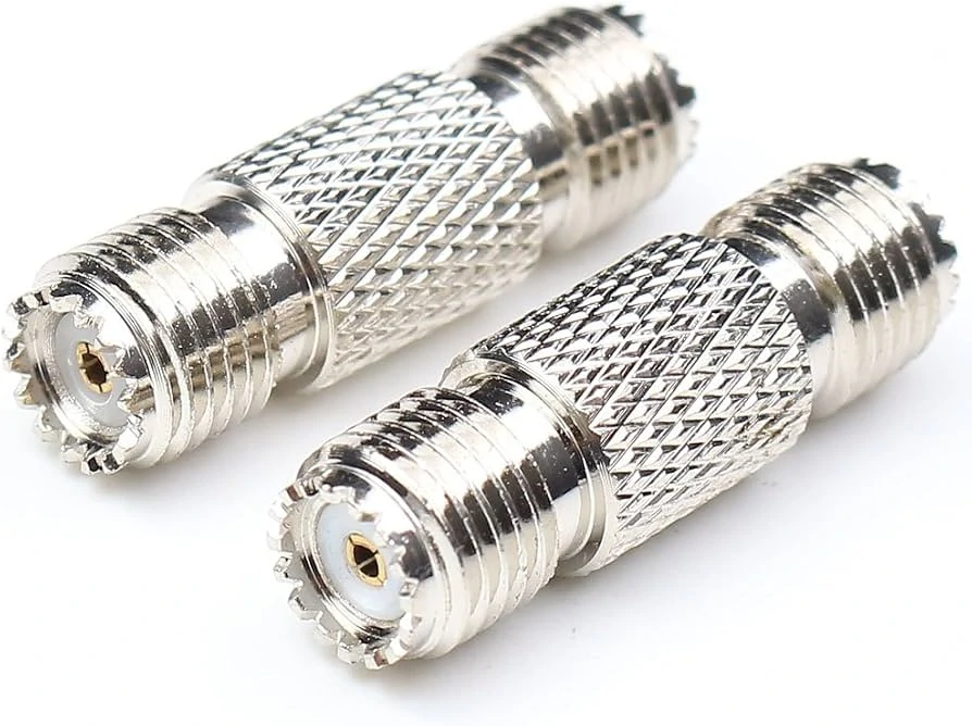
Straight Mini-UHF female-to-female coaxial adapters featuring knurled bodies for easier handling and connecting two compatible Mini-UHF male interfaces.
Start with the equipment port, not the loose cable in the installer’s hand. The port defines the mating connector, gender, thread engagement, and mechanical clearance. If the port is recessed in a radio chassis or mounted behind a panel, a correct RF interface may still fail if the connector body is too large or the cable exits at the wrong angle.
Check the coupling diameter, thread structure, center contact, equipment model, existing mating cable, and manufacturer drawing. If the equipment has an old cable attached, keep it as a reference until the replacement is fully verified. The old part can reveal whether the system used a straight plug, right-angle plug, molded cable assembly, or adapter stack.
Mini-UHF should also be kept separate from PL-259 and SO-239 terminology. PL-259 is commonly associated with full-size UHF cable plugs, while SO-239 usually refers to the matching equipment-side receptacle. Mini-UHF is a smaller connector family. It may appear in the same mobile-radio environment, but the hardware is different. If your project also includes full-size UHF interfaces, compare that separately in TEJTE’s UHF connector guide before mixing connector names in the RFQ.
A label such as “UHF radio” is not enough. In procurement language, separate four items: radio frequency band, connector family, connector gender, and cable termination. A 450 MHz radio may not use a UHF-family connector at all. A Mini-UHF port may be paired with RG58, RG142, RG223, RG400, or another coax depending on the connector part number and assembly design.
This small table prevents a common sourcing mistake: treating “Mini-UHF” as a complete specification. It is only the connector family. The exact cable-side plug or jack still needs a gender, cable group, impedance, body style, and termination method.
Which male or female configuration actually mates with the equipment?
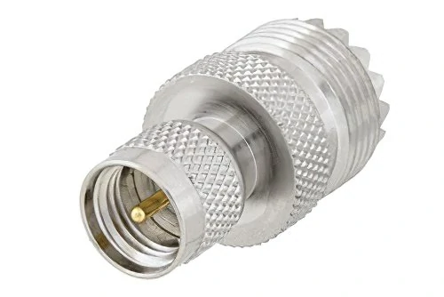
A straight Mini-UHF male to UHF female RF adapter used to convert between compact Mini-UHF equipment ports and standard UHF coaxial connectors.
After the connector family is confirmed, identify the mating role. Do not rely only on the words male and female without looking at the center contact and body style. RF connector gender can be misunderstood because some people describe the shell, while others describe the center pin or socket. For Mini-UHF purchasing, the approved manufacturer drawing or existing mating connector is more reliable than a verbal description.
In many mobile-radio installations, the equipment side is a receptacle and the cable side uses a Mini-UHF plug. But that is not universal enough to order blindly. Mini-UHF product families can include cable plugs, cable jacks, PCB receptacles, panel-mount receptacles, straight bodies, right-angle bodies, and bulkhead-style configurations. A mini UHF male connector may be correct for one radio cable and wrong for another if the port, panel depth, or coax routing is different.
The safest method is to map the equipment side and cable or adapter side separately. On the equipment side, record whether the interface is a plug or jack, whether the center contact is a pin or socket, and whether it is chassis, PCB, or panel mounted. On the cable side, confirm the connector type, coax compatibility, exit direction, and approved mating part number. This is especially important when replacing an old harness where the visible connector face is correct but the rear cable construction has changed.
This table is useful because many purchasing errors are not electrical errors at first. The cable may show continuity, the connector may start threading, and the part may look similar in a photo. The problem appears later when the plug bottoms out incorrectly, the coupling nut does not fully retain, or the cable exits into a bracket and creates strain on the port.
For repeat orders, save the verified connector callout as a complete line item: Mini-UHF family, plug or jack, male or female contact, impedance, cable type, body style, termination method, and approved mating equipment port. If the assembly will convert to another interface later, keep that decision for the adapter section rather than hiding it inside the Mini-UHF connector description.
How do you match a Mini-UHF connector to RG58?
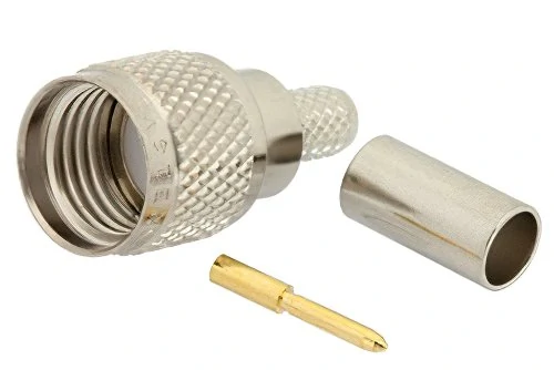
A disassembled Mini-UHF male cable connector displaying its connector body, gold-plated center contact, and metal ferrule for coaxial cable termination.
Treat RG58 as a cable family, not as a complete connector specification. A buyer may write “mini UHF connector RG58” in the RFQ, but the supplier still needs the physical cable dimensions and termination style. RG58, RG58A/U, RG58B, RG58C, and similar market descriptions can vary by jacket material, braid construction, conductor type, and actual outside diameter. Those details decide whether the rear body, center contact, ferrule, and crimp sleeve fit correctly.
The front mating face only tells you whether the connector can mate with the Mini-UHF port. It does not prove the rear side fits the coax. Two Mini-UHF cable plugs may look almost identical from the front, while using different rear bores, ferrules, contact sizes, or cable-preparation dimensions. This is why connector selection should be approved by exact part number, not only by connector family.
This matrix is especially useful when one project uses RG58 and another uses RG142, RG223, RG400, or a low-loss alternative. A Mini-UHF connector that works well on one cable may fail pull retention, crimp height, or RF consistency on another. For broader cable comparison, keep the cable choice aligned with an RG cable guide rather than forcing one connector onto every coax type.
When should you choose a crimp Mini-UHF connector?
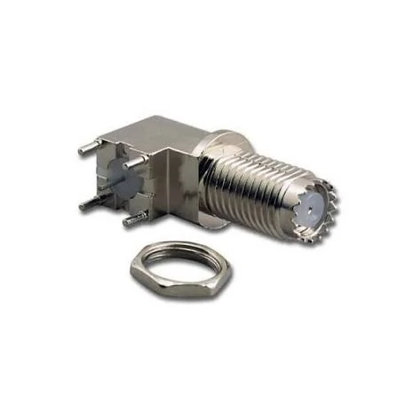
A right-angle Mini-UHF female receptacle with PCB terminals and a mounting nut, suitable for compact radio equipment and panel-mounted RF interfaces.
Choose a mini UHF crimp connector when repeatability matters more than field improvisation. Crimp termination is usually preferred for production cable assemblies, fleet-radio harnesses, and repeat orders where the same coax, stripping length, ferrule, die set, and inspection method can be controlled. It also helps reduce operator variation compared with a purely hand-soldered process.
A common mistake is assuming that “crimp” describes the whole connector in one step. In practice, the center contact and shield ferrule may require different tooling, different die cavities, or even different processes. Some connectors use a crimp center contact and crimp ferrule; others may combine solder, clamp, or mixed assembly steps. The correct question is not “Is crimp better?” but “Does this exact Mini-UHF connector and coax combination call for crimp, solder, clamp, or a mixed process?”
Use this termination decision matrix for production planning:
| Requirement | Crimp | Solder / mixed | Factory assembly |
| Production speed | High | Medium | High |
| Tool control | Required | Moderate | Supplier-controlled |
| Operator dependence | Lower when tooled | Higher | Lower |
| Field repair | Limited | Easier in some cases | Replace assembly |
| Pull consistency | Strong if validated | Process-dependent | Validated by supplier |
| RF repeatability | Good if controlled | Operator-dependent | Batch controlled |
| Traceability | Tool + lot records | Operator records | Supplier test report |
| Best use | Repeated builds | Repair or special builds | Stable BOM orders |
For repeat cable assemblies, ask for the connector part number, cable type, crimp tooling reference, cable prep drawing, and inspection method. If the assembly is for a vehicle, vibrating cabinet, or frequently serviced radio, also define pull retention and strain relief instead of only checking continuity.
How should the finished cable be routed behind the connector?
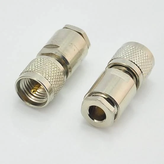
Two straight Mini-UHF male cable connectors with threaded coupling interfaces and rear cable entries for radio, antenna, and coaxial cable assemblies.
A compact connector does not remove the need for cable support. Mini-UHF is useful where space is limited, but the smaller interface should not become the first bend point of a stiff cable. After installation, the cable should leave the connector with a short no-bend zone, then be supported by a clamp, tie point, service loop, or panel path that keeps side load away from the port.
The risk increases when a heavy cable is attached to a small chassis port, when the cable exits at an angle, or when the equipment is installed in a vehicle with vibration. Even a correct connector can loosen, rotate, or fatigue if the cable is allowed to pull on the termination.
Score each installation factor from 0 to 2 before approving the layout:
| Factor | 0 | 1 | 2 |
| Cable stiffness | Low | Medium | High |
| Cable support | Near connector | Moderate distance | None |
| Equipment movement | Fixed | Periodic | Frequent |
| Vibration | None | Moderate | Continuous |
| Connector overhang | Short | Medium | Long |
| Service frequency | Rare | Occasional | Frequent |
How much RF performance should you expect from Mini-UHF?
Use the exact product rating instead of the connector nickname. Mini-UHF is commonly used in 50-ohm RF systems, and some manufacturer families support frequencies up to the low-GHz range, but that rating should not be applied blindly to every Mini-UHF part number, cable type, adapter, and finished assembly.
Do not transfer PL-259 assumptions to Mini-UHF. Standard UHF and Mini-UHF are separate connector families, and the RF result depends on the complete path: connector geometry, cable loss, termination quality, adapter count, bend state, and mating condition. For low-frequency mobile-radio work, the connector may be mechanically selected first. For higher-frequency or measurement-sensitive systems, the finished assembly should be tested.
For production orders, request test conditions when they matter: S11, S21, frequency range, cable length, bend state, and mating cycles. Continuity alone only proves that the inner and outer conductors are connected correctly. It does not prove insertion loss, return loss, shielding condition, or connector repeatability.
When should a direct connector become a Mini-UHF cable or jumper?
Use a mini UHF cable or jumper when the two ports are not naturally aligned, when the cable must move, or when a rigid adapter stack would place leverage on the equipment port. This is common in mobile-radio installations, equipment-to-panel transitions, short service leads, and vehicle harnesses.
A rigid chain may look convenient during sourcing:
Equipment → rigid adapter → second adapter → cable
But in the actual installation, that stack can add weight, length, torque, and extra mating interfaces. A purpose-built Mini-UHF cable assembly often gives better strain relief, easier routing, and fewer mechanical surprises.
Use this quick decision tree: Are both ports aligned? Will either side move? Is the coax stiff? Is the connection repeatedly serviced? Is more than one adapter required? Can the cable be strain-relieved? If several answers create risk, specify a cable assembly instead of forcing a direct connector or adapter chain.
How should Mini-UHF to BNC or SMA conversions be selected?
Use a Mini-UHF to BNC adapter when the destination side is a BNC-based radio, test instrument, antenna lead, or patch panel. Use a Mini-UHF to SMA adapter when the connection must transition into compact RF modules, SDR hardware, small test cables, or modern SMA-based equipment. In both cases, the adapter should be selected from the two ends inward: Mini-UHF gender first, destination connector gender second, then impedance, frequency range, body length, and mechanical support.
Do not choose the adapter only because the names match. A mini UHF to BNC adapter can still be wrong if the BNC side has the wrong gender or impedance. A mini UHF to SMA adapter can also create a mechanical problem if a long rigid adapter is attached directly to a small radio port and then loaded by a stiff SMA cable.
| Source port | Destination port | Adapter ends | Impedance | Mechanical risk | Best use |
| Mini-UHF | BNC | Mini-UHF plug/jack to BNC plug/jack | Usually 50Ω, confirm | Medium | Radio to BNC test or cable system |
| Mini-UHF | SMA | Mini-UHF plug/jack to SMA male/female | Usually 50Ω, confirm | Medium to high if long | Compact RF test, SDR, module connection |
| Mini-UHF | Other RF connector | Confirm both sides | Confirm | Depends on adapter length | Only when the equipment interface requires it |
If more than one adapter is needed, pause and review the layout. A purpose-built cable assembly is often cleaner than stacking rigid transitions. TEJTE’s related coax adapter compatibility guide can be used when the project involves several connector families in the same RF path.
Validate mating retention before trusting continuity
Continuity is not enough to approve a Mini-UHF connection. A cable can pass a basic electrical check while the connector is only partially seated, the threads are damaged, the center contact is worn, or the cable is loading the port. For a compact threaded RF interface, mating retention and cable retention should be checked separately.
Mating retention means the connector stays fully engaged with the equipment. Cable retention means the coax remains securely terminated inside the connector body. These are different failure modes. A connector can remain attached to the port while the cable termination is weak, or the cable can be well-crimped while the Mini-UHF interface loosens after vibration or repeated servicing.
For installations that will be serviced often, cycle the connector during first-article approval. Record first mating, repeated mating, thread wear, contact repeatability, and signal stability. This helps catch problems that do not appear in a single bench check.
Build the supplier RFQ around the exact cable and equipment port
A weak RFQ says “Mini-UHF connector needed.” A useful RFQ says “Mini-UHF plug or jack, 50Ω, cable-mount, for approved coax part number, with defined termination and test requirements.” The second version gives the supplier enough information to quote the correct connector or cable assembly instead of guessing from a family name.
Lock the connector and cable into one controlled BOM. Include the equipment port, connector part number, cable part number, cable outside diameter, termination method, tooling requirement, finished length, and body style. If the project needs a right-angle connector, panel transition, or adapter conversion, state that directly.
For buyers comparing connector options, it also helps to state whether the part is for repair, production assembly, field installation, or new equipment design. The best Mini-UHF choice is not always the smallest or cheapest connector; it is the one that mates correctly, fits the cable, survives the route, and meets the RF requirement after assembly.
How should incoming Mini-UHF lots be screened?
Incoming inspection should catch obvious interface errors before parts enter production. Check the male/female configuration, thread condition, center contact, plating, body damage, cable assignment, and label. If the order is for finished Mini-UHF cable assemblies, also check cable length, connector orientation, heat-shrink position, and whether the cable matches the approved BOM.
Increase sampling after any supplier change, cable change, tool change, drawing revision, or previous failure. If the application frequency is important, add RF sampling with S21 and return-loss checks instead of relying only on continuity.
| Characteristic | Method | Sampling | Acceptance | Failure action |
| Connector identity | Visual | 100% | Drawing match | Quarantine |
| Thread/contact | Visual | 100% | No damage | Sort |
| Cable fit | Dimension | Sample | Drawing match | Hold |
| Cable retention | Pull test | Risk-based | Project limit | Expand sample |
| Continuity | Electrical | Plan | Pass | Rework |
| S21 | VNA | Risk-based | RFQ limit | Investigate |
| Return loss | VNA | Risk-based | RFQ limit | Investigate |
The final approval should connect back to the original equipment port and cable requirement. If the lot passes inspection but the assembly still fails in the routed installation, review cable bend radius, adapter leverage, mating retention, and the installed RF path.
FAQ
How can I tell a Mini-UHF connector from a PL-259 without removing the radio?
Compare the actual mating interface, thread geometry, connector body size, existing cable end, and equipment documentation. Mini-UHF and PL-259/SO-239 are separate connector families, so they should not be treated as direct size variants. If the connector cannot be clearly identified from the front panel, use the equipment model or drawing before ordering.
Can every Mini-UHF connector terminate RG58?
No. RG58 compatibility depends on the exact rear body, ferrule, center contact, cable-preparation size, and termination method. Some Mini-UHF connectors are made for RG58-class cable, while others are designed for different coax groups. Always approve the connector and cable as one matched pair.
Does every Mini-UHF connector automatically work to 2.5 GHz?
No. Frequency capability belongs to the exact connector design, cable, adapter, and finished assembly. Some Mini-UHF product families include parts rated up to the low-GHz range, but the safest approval method is to check the datasheet and test the assembled cable when the application is frequency-sensitive.
When is a Mini-UHF cable better than a rigid adapter?
A Mini-UHF cable or jumper is usually better when the ports are offset, the equipment moves, the coax is stiff, or a rigid adapter would place torque on the radio port. A short flexible assembly can reduce side load and make the installation easier to service.
Can Mini-UHF-to-BNC and Mini-UHF-to-SMA adapters carry RF in either direction?
A passive coaxial adapter normally does not have a fixed RF input or output direction. What matters is the connector gender on both ends, impedance, frequency range, mating condition, and mechanical layout. Direction becomes important only when the assembly includes active or directional RF components.
What should be inspected first if a Mini-UHF connection becomes intermittent?
Start with thread engagement, center contact condition, connector rotation, cable pull retention, and movement near the termination. Intermittent faults often come from mechanical wear, side load, or repeated servicing, even when the cable passed static continuity earlier.
Should a Mini-UHF cable assembly be RF-tested after installation?
For production-critical, frequency-sensitive, or mechanically stressed installations, yes. Test the assembly in the final routed condition when possible. Cable bending, adapter leverage, port loading, and repeated mating can change the measured RF result compared with a loose bench assembly.
A reliable Mini-UHF specification is built from the complete connection, not from the connector name alone. Confirm the equipment port, select the correct male or female configuration, match the coax, define the termination, control the cable route, and screen incoming lots against measurable RF and mechanical limits. That process gives buyers, installers, and suppliers the same target before the first production cable is made.
