
A cable can screw on cleanly and still be the wrong RF connection.
That happens often with UHF-style radio hardware. A buyer asks for a PL259 connector, the supplier sends a part that looks right, and the first check passes because the center conductor is not shorted to the shield. Then the assembly is installed on a radio, antenna tuner, CB system, or field antenna, and the SWR is higher than expected. The problem may not be the radio. It may be the connector naming, the cable fit, the SO239 mating side, or a solder joint that looked acceptable before RF testing.
PL259 is simple only if the whole RF path is simple. In real sourcing work, it sits inside a group of names: PL-259 connector, UHF male connector, UHF plug, SO239 connector, SO-239 socket, UHF female connector. Those names are often used loosely. That is where ordering mistakes start.
How Does a PL259 Connector Fit Into UHF Coax Systems?
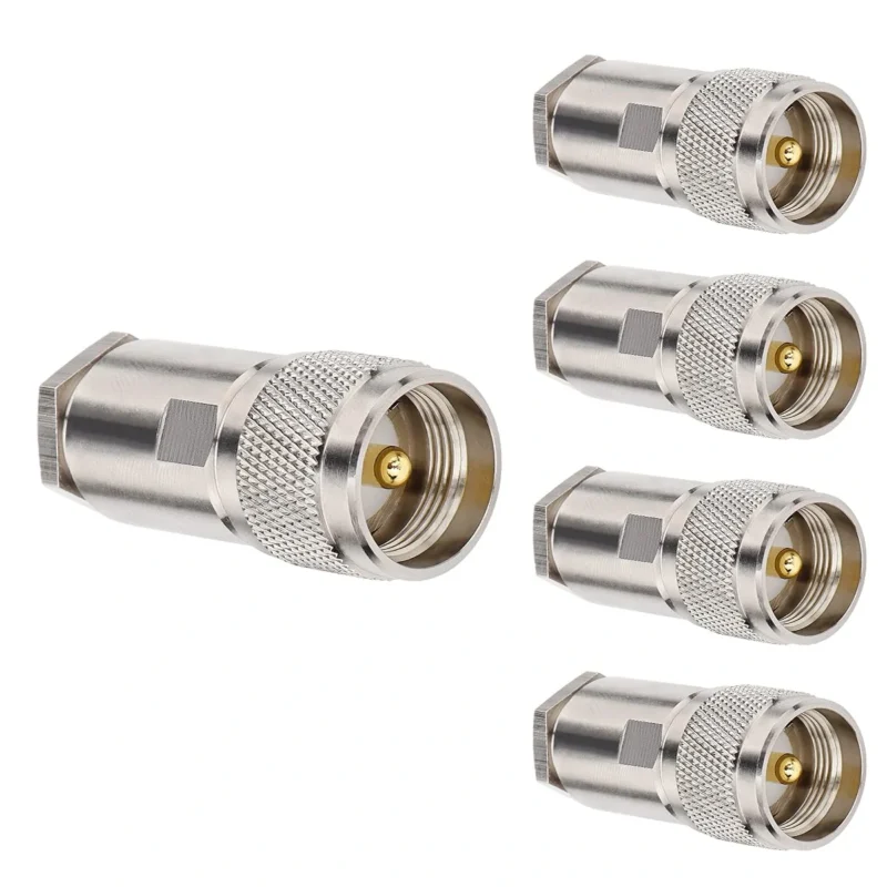
PL259 is often called a UHF connector, but “UHF” in this connector family is historical naming. It should not be read as a promise that the part is suitable for every modern ultra-high-frequency RF design. A UHF connector may work well enough in many HF and VHF radio systems, yet still be a poor choice for tighter high-frequency measurement work where impedance control and repeatable return loss matter more.
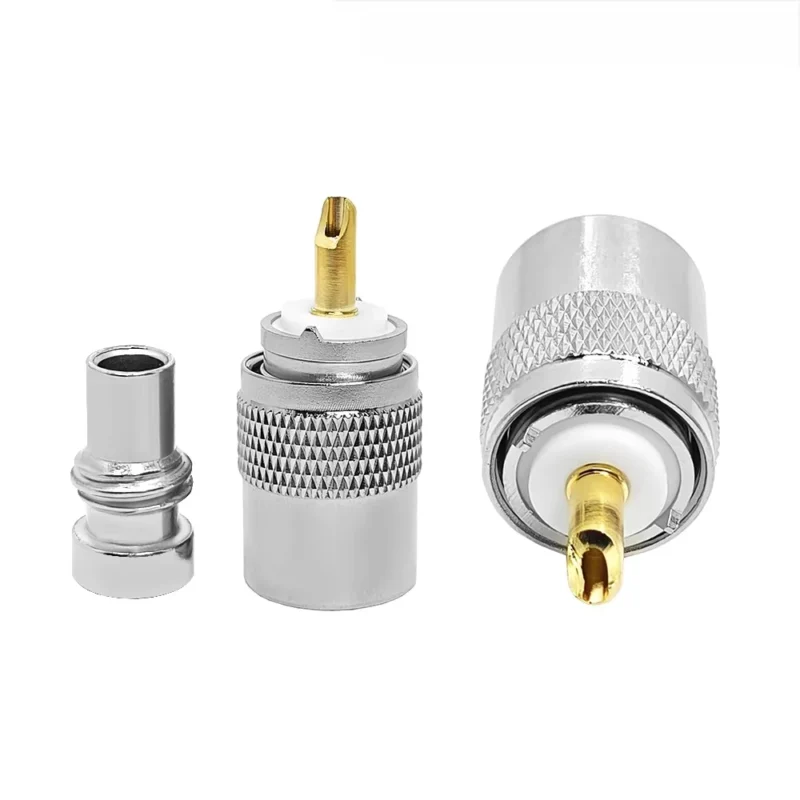
In practical radio use, PL259 usually means the male plug side installed on a coax cable. The mating socket is usually called SO239. A complete antenna feed line may use PL259 plugs at one or both cable ends, depending on the radio, antenna, adapter, or panel interface.
The confusing part is that many people do not say “PL259” and “SO239” precisely. They say “UHF connector.” That may mean a cable plug, a panel socket, a barrel adapter, or an adapter from UHF to BNC, N Type, or SMA. For purchasing, that wording is not enough.
A better RF request starts with the actual connection:
“PL259 male plug for RG213 coax, solder type, 50 ohm radio antenna cable assembly, mating with SO239 female socket.”
That sentence removes several risks at once. It defines the plug side, cable type, assembly method, impedance expectation, and mating interface. It also tells the supplier not to quote a random UHF adapter or a socket-style part.
Why PL259 is common in radio and antenna work
PL259 connectors are still common because many radio systems were built around them. Ham radio transceivers, CB radios, antenna tuners, base antennas, field radio setups, and older RF equipment may use SO239 sockets as the equipment-side interface. If the equipment already uses SO239, a PL259 plug is the normal mating choice.
This does not mean the connector should be selected by habit. A PL259 connector for RG58 is not automatically suitable for RG213. A part shown in a product photo may have the correct front thread but the wrong rear body, reducer, solder window, or cable clamp. The cable may fit loosely, the braid may not be captured properly, or the dielectric may deform during soldering.
The RG cable guide should be checked before connector selection because cable size and construction decide whether the connector can be assembled repeatably. A connector is not just the front interface. The rear cable entry is just as important.
Where UHF connector naming becomes risky
The term “UHF connector” creates three common sourcing errors.
First, the buyer may need a PL259 plug but receive an SO239 socket. Second, the buyer may need a cable connector but receive a panel connector. Third, the buyer may choose a connector body that fits a different coax family.
These mistakes are easy to miss in text-only communication. “Need UHF head for radio cable” is not a complete RF specification. It does not say male or female. It does not say cable mount or panel mount. It does not say RG58, RG8X, RG213, LMR400, or another cable. It does not say solder, crimp, or clamp type.
For a one-off field cable, the installer may correct the issue by changing reducers or reworking the cable. For production or resale, that becomes expensive. Wrong rear-body fit leads to rework, inconsistent soldering, cable pull failures, and customer complaints about SWR or loose connection.
How Do PL259 and SO239 Connectors Work Together?
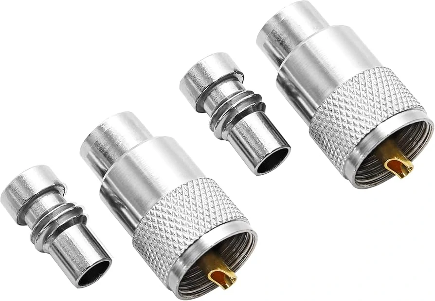
PL259 and SO239 connectors are commonly used as a matching pair in UHF connector systems. The PL259 male plug is normally installed on coaxial cables, while the SO239 female socket is mounted on radios, antennas, panels, or RF equipment.
PL259 and SO239 should be treated as a mating pair, not as interchangeable names.
PL259 is normally the plug. It is usually attached to the coax cable. SO239 is normally the socket or jack. It is often mounted on a radio, antenna, panel, adapter, enclosure, or test fixture. The two parts thread together and create the RF path through the center contact and outer shield connection.
That sounds obvious, but it is one of the most common UHF connector ordering problems. A customer may search for “SO239 connector” while actually needing a PL259 cable plug. Another may ask for a “UHF female connector” and expect an adapter, while the supplier quotes a panel socket. In RF sourcing, the name has to match the mechanical role.
The front interface also does not solve the cable question. A PL259 connector can mate with SO239, but that does not prove the coax cable is correctly terminated. The cable OD, center conductor size, braid coverage, reducer sleeve, and solder method still need to match.
PL259 side: cable-end plug
A PL259 plug is usually installed on the coax cable end. It may be used on antenna feed lines, jumper cables, test leads for radio equipment, and field radio cables. The cable may be thinner, such as RG58 or RG8X, or thicker, such as RG213, depending on the connector design.
For buyers, the PL259 side should be described with cable details:
- Cable type
- Cable outside diameter
- Center conductor type
- Solder or crimp requirement
- Reducer requirement
- Target frequency band
- Power level if relevant
- Assembly length if ordering a finished cable
Do not assume a supplier can infer all of that from “PL259 plug.” They may quote the most common model in stock. That model may not fit the cable you plan to use.
SO239 side: socket, jack, or panel interface
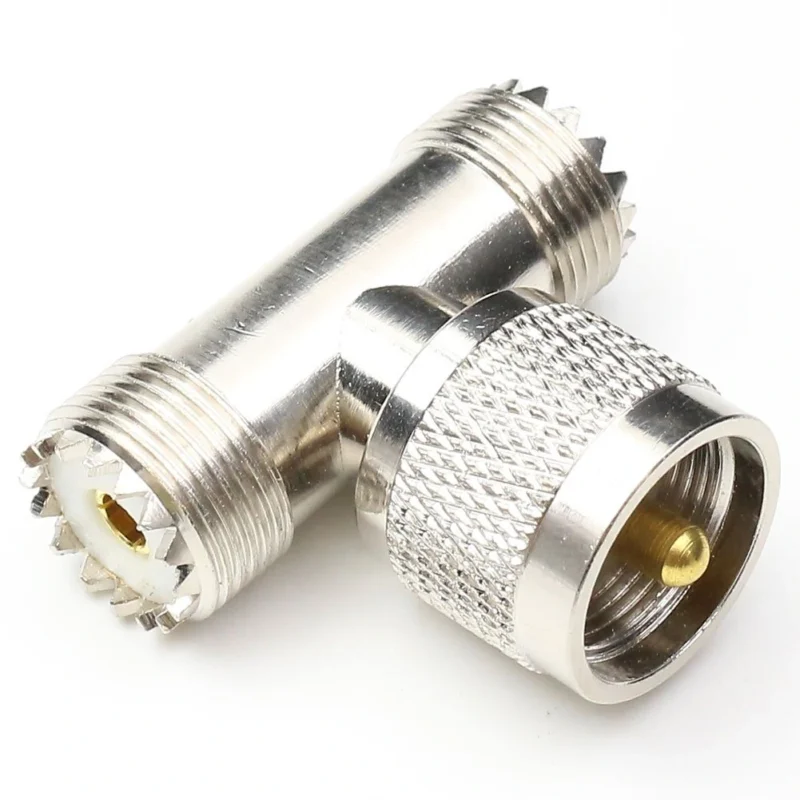
SO239 is usually the female socket side. It may be mounted on the radio chassis, antenna base, bulkhead panel, lightning arrestor, adapter, or enclosure. It may also appear in adapter products, such as SO239 to BNC, SO239 to N Type, or SO239 to SMA.
The most important purchasing detail is the mounting style. A socket may be a panel jack, bulkhead jack, flange mount, or adapter-side socket. These are not the same part, even if they all mate with PL259.
For equipment repair or panel installation, confirm the hole size, mounting thread, flange size, insulation material, and grounding method. A socket that mates electrically but does not fit mechanically is still the wrong component.
PL259 vs SO239 identification table
Use this table before quoting or ordering. It is simple, but it prevents many wrong-part conversations.
| Check Item | PL259 | SO239 |
| Common role | Plug | Socket / jack |
| Typical location | Coax cable end | Radio, antenna, panel, adapter |
| Common search term | PL259 connector, PL-259 plug | SO239 connector, SO-239 socket |
| Usual gender wording | UHF male connector | UHF female connector |
| Mating part | SO239 | PL259 |
| Main ordering risk | Wrong cable size or reducer | Wrong mount style or adapter direction |
| Buyer should confirm | Cable type, termination, cable OD | Panel type, thread, flange, mating side |
This table should not replace a drawing or datasheet. It is a first-pass filter. If the connector will be used in production, outdoor antenna work, or a finished cable assembly, the supplier still needs the cable specification and the application frequency.
A short example of a complete RF request
A weak request sounds like this:
“Need UHF connector for radio cable.”
A useful request sounds like this:
“Need PL259 male connector for RG213 coax cable, solder type, 50 ohm radio antenna feed line, mating with SO239 socket on HF/VHF transceiver. Please confirm cable OD fit and reducer requirement.”
That version gives the supplier enough information to check the rear body, cable entry, and assembly method before quoting. It also reduces the chance of receiving an SO239 socket when the real need is a PL259 plug.
How Should You Match PL259 Connectors With Coax Cable?
The front side of a PL259 connector gets too much attention. Buyers see the UHF male interface, check that it mates with SO239, and assume the connector is correct. The rear side is where many failures begin.
A PL259 connector must match the coax cable body. That means the cable outside diameter, dielectric size, braid structure, jacket thickness, and center conductor must all suit the connector design. If the cable is too small, the shield contact may be weak and the strain relief may not hold. If the cable is too large, the braid may be cut, folded unevenly, or overheated during assembly.
RG58, RG8X, RG8, RG213, and some LMR-series cables may all appear in radio antenna work, but they do not use the same rear dimensions. A PL259 plug made for RG58 should not be treated as a universal UHF connector. The connector may screw into the same SO239 socket, yet the cable termination may be wrong.
Choose the cable size before choosing the connector body
For a finished RF cable assembly, the first question should not be “Do you have PL259?” It should be “Which coax cable will this PL259 terminate?”
RG58 is often used for shorter flexible radio leads. RG8X is common in lightweight antenna jumpers. RG213 is thicker and more rugged, often selected for outdoor or higher-power radio coax. LMR400-style cables are used where lower loss is needed over longer antenna runs, but the connector must be designed for that cable size.
A reducer may be needed when a PL259 body is used with a smaller coax. That reducer is not a cosmetic accessory. It helps center and support the cable, controls how the braid is terminated, and affects repeatability during assembly. Without the correct reducer, two cables made from the same parts can perform differently after bending or pulling.
Use a cable fit matrix before ordering
The table below is a practical sourcing filter. It does not replace a drawing, but it helps avoid the most common “photo looks right” mistake.
| Field | What to Confirm | Why It Matters |
| Cable type | RG58 / RG8X / RG8 / RG213 / LMR400 | Different cable families need different rear-body dimensions |
| Cable OD | Actual mm or inch value | Prevents loose fit or forced assembly |
| System impedance | Usually 50 ohm for radio coax | Avoids mixing with unsuitable cable or adapter paths |
| Termination style | Solder / crimp / clamp | Changes tools, inspection, and repeatability |
| Reducer needed | Yes / No / specific size | Controls fit for smaller coax |
| Frequency band | HF / VHF / UHF radio band | Helps decide if UHF connector is still acceptable |
| Power level | Low / medium / high | Affects cable choice, solder quality, and heat risk |
| Application | Ham / CB / antenna / field / test | Defines mechanical and inspection expectations |
| Decision | Fit / Review / Not compatible | Forces a sourcing decision before production |
The most useful row is often “Decision.” If the supplier cannot confirm cable fit, the order should stay in review. A wrong PL259 connector can still be assembled by force, but that is not the same as a stable RF cable assembly.
For production orders, write the cable into the BOM line. For example:
“PL259 male plug, 50 ohm, solder type, for RG213 coax, mating with SO239 socket, used for HF/VHF radio antenna feed line, visual and SWR check required.”
That is much safer than “UHF plug.”
How Do Frequency Range and Impedance Affect UHF Connector Selection?
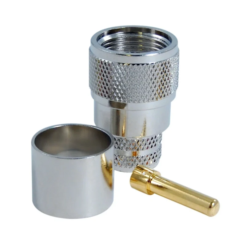
A PL259 connector can be useful and still have limits.
UHF connectors were not designed as precision constant-impedance connectors in the same way as many modern RF interfaces. Their geometry creates discontinuities in the RF path, especially as frequency rises. At lower radio frequencies, that may be acceptable. Near higher VHF or UHF use, the connector, cable, solder quality, and adapter stack should be checked more carefully.
Do not judge the RF path by continuity alone. A cable can pass center-to-center continuity, shield-to-shield continuity, and center-to-shield isolation, then still show poor SWR in the operating band. Continuity confirms that the path is not open or shorted. It does not confirm impedance behavior.
Check the real operating band before using PL259
PL259 and SO239 connectors are common in HF, CB, and many VHF radio setups. They may also appear in older equipment that still uses UHF sockets as standard. For these systems, compatibility and availability often matter more than precision microwave behavior.
The risk increases when the same connector is used as a casual substitute for SMA, N Type, TNC, 3.5 mm, or 2.92 mm interfaces. A UHF connector may physically complete a path through adapters, but that does not make it suitable for high-frequency RF testing or low-VSWR measurement.
If the system is only a basic radio antenna line, the connector may be fine. If the system is a calibrated test setup, a higher-frequency wireless module, or a sensitive measurement chain, the safer decision is to use an interface designed for that frequency range and impedance consistency.
Understand why UHF connectors are not precision constant-impedance parts
A precision connector tries to keep the impedance transition controlled through the interface. UHF connectors are older mechanical designs, and the mating geometry is less controlled. The center contact, socket structure, dielectric support, and outer conductor transition can create mismatch.
This does not make every PL259 cable “bad.” It means the part should be used where its trade-offs are acceptable.
A short HF radio jumper may work normally. A long antenna feed line with multiple adapters, outdoor stress, and poor soldering may show loss and SWR problems that are hard to diagnose. The connector is only one piece of that path, but it is a piece that buyers can specify better.
When Should You Use UHF Adapters Instead of Rebuilding the Cable?
Adapters are useful when the equipment interfaces do not match and the installation is temporary, low-risk, or easy to inspect. A UHF adapter can connect radio equipment to test gear, transition an older antenna line to a newer device, or support bench troubleshooting without rebuilding a finished cable.
That does not mean adapters should be stacked without thought. Every adapter adds another interface. Each interface can add insertion loss, reflection, mechanical leverage, and another point that can loosen in the field.
Use a UHF adapter for short-term interface transitions
A UHF adapter makes sense for bench testing, radio-to-antenna transitions, and legacy equipment support. For example, a technician may use a BNC to UHF adapter to connect test equipment to a radio cable. A handheld radio user may use an SMA to UHF adapter to connect a compact radio to a PL259 antenna cable.
For occasional testing, that may be acceptable. For permanent installation, a custom cable assembly is often cleaner. One cable with the correct connector on each end usually has fewer failure points than a cable plus two or three adapters.
The RF adapter cables category can be a better direction when the transition is known in advance. Instead of stacking adapters, specify interface A, interface B, cable type, length, impedance, and target frequency.
Avoid adapter stacks when a custom cable is cleaner
Adapter stacks often look harmless on the bench. The radio receives signal, the antenna connects, and the path passes a quick test. The trouble appears later when the assembly is moved, bent, pulled, or exposed outdoors.
A long stack hanging from an SO239 socket can create mechanical stress. If the adapter is connected to a small SMA device, the stress may be even worse. The connector may not fail immediately. It may loosen slowly, damage the center contact, or create an intermittent shield connection.
For repeat orders, adapter stacks should be treated as a warning sign. If the same transition is used again and again, build it into the cable.
How Does a UHF Connector Compare With N Type, BNC, and SMA?
UHF, N Type, BNC, and SMA connectors can all appear in radio and RF environments, but they solve different problems. The question is not which one is “better.” The real question is which interface matches the cable size, frequency, mechanical environment, and equipment standard.
| Requirement | UHF / PL259 | N Type | BNC | SMA |
| Legacy ham / CB radio compatibility | High | Medium | Medium | Low |
| Large coax cable fit | Good | Good | Medium | Low |
| Outdoor antenna feed | Medium | High | Low to medium | Low |
| Quick bench connection | Medium | Low | High | Low |
| Compact RF module use | Low | Low | Medium | High |
| Precision high-frequency testing | Low to medium | Medium to high | Medium | High |
| Threaded mechanical security | Medium | High | No, bayonet style | High, small format |
N Type is often the stronger choice for outdoor antenna infrastructure and higher-frequency systems where better impedance behavior and mechanical sealing matter. BNC is useful on test benches because it connects quickly. SMA is common on compact RF modules, SDRs, antennas, Wi-Fi/GPS-style equipment, and many smaller devices.
UHF / PL259 remains useful because the installed base is large. Many radios and antenna systems still use SO239 sockets. Replacing the interface may not be practical. In that case, the best approach is not to pretend PL259 is a precision microwave connector. The best approach is to specify the cable correctly, avoid unnecessary adapters, and test the assembly in the band where it will actually be used.
How Can You Install a PL259 Connector Without Signal Problems?
Most PL259 problems do not begin at the threaded interface. They begin at the cable preparation bench.
The shield is cut unevenly. The center conductor is too short. The dielectric softens from too much soldering heat. The braid is not fully captured. The jacket is not supported. The connector looks finished, but the RF path is already compromised.
PL259-style plugs are often soldered, so workmanship matters. A cold solder joint may pass a quick visual check and still cause intermittent contact. Too much heat can deform the dielectric around the center conductor. Poor shield contact can raise SWR, especially after the cable is bent or pulled during installation.
Prepare the coax before soldering
A good PL259 installation starts with controlled cable stripping. The installer should avoid nicking the center conductor, cutting too much braid, or leaving loose shield strands near the dielectric. A single stray braid wire can create a short or unstable leakage path.
The center conductor length also matters. If it is too short, the center contact may be weak. If it is too long, it may bottom out or create stress during mating. For thick coax such as RG213, the braid and jacket also need enough support so the finished connector does not rely only on solder for mechanical strength.
For repeat production, use a stripping reference sample or controlled work instruction. “Strip by experience” may be acceptable for one field repair, but it is not a stable production method.
Inspect the finished connector before RF testing
Visual inspection should happen before the cable reaches a VNA, antenna analyzer, or radio. The goal is to catch obvious mechanical defects early.
Check the center pin alignment, thread condition, shell tightness, solder window, braid contact, and insulation condition. Then check for center-to-shield short. If the cable will be used outdoors or in field radio work, also check strain relief and any sealing method.
A PL259 cable that fails visually should not be “saved” by RF testing. Rework it first.
How Should You Test a PL259 Cable Assembly Before Use?
Continuity testing is necessary, but it is not enough.
A basic meter can confirm center-to-center continuity, shield-to-shield continuity, and center-to-shield isolation. That catches opens and shorts. It does not prove that the assembly behaves well at the operating frequency.
For radio users, SWR testing in the actual band is more useful. For production or technical buying, return loss or VSWR values should be checked when the application requires it. If the cable is only used in a basic HF radio setup, the test requirement may be simple. If it will be used near the upper practical range of the connector family, inspection should be stricter.
PL259 assembly acceptance sheet
Use this acceptance sheet for production, incoming inspection, or field cable verification.
| Field | Record |
| Cable type | RG58 / RG8X / RG213 / LMR400 / other |
| Connector side A | PL259 / other |
| Connector side B | SO239 / N / BNC / SMA / other |
| Assembly length | ft / m |
| Continuity | Pass / Fail |
| Center-to-shield short check | Pass / Fail |
| VSWR / return loss | Value and test frequency |
| Pull / strain check | Pass / Fail |
| Visual inspection | Pass / Fail |
| Final result | Accept / Rework / Reject |
The test frequency should be written down. “VSWR passed” is not specific enough. A cable that is acceptable at one band may not be acceptable at a higher band, especially if it includes adapters or rough soldering.
Troubleshoot high SWR step by step
When a PL259 cable shows high SWR, do not blame the connector first. Check the whole path.
Start with the antenna or load. Then check the cable length, connector installation, adapter count, SO239 socket condition, water ingress, and mechanical looseness. If there are multiple adapters, remove them one by one and test again. If the issue disappears after removing an adapter stack, the cable may not be the only problem.
A useful rule: test the shortest clean path first. Then add each part back into the RF chain.
How Do You Specify the Right PL259 Connector for Ordering?
A good PL259 request should be boring. Boring means complete.
Before asking for price, confirm the connector name, mating side, cable type, cable OD, termination method, reducer requirement, frequency range, power level, quantity, and application. If the cable assembly is custom, also confirm length, opposite-end connector, labeling, packing method, and inspection requirement.
Write the requirement as a complete line
Weak BOM note:
“UHF connector.”
Better BOM note:
“PL259 male plug for RG213 coax cable, 50 ohm, solder type, mating with SO239 socket, for HF/VHF radio antenna cable assembly, VSWR check required at target band.”
For an adapter, write both interfaces clearly:
“BNC male to UHF female adapter, 50 ohm, for radio test bench transition, confirm frequency range and mechanical load.”
For a custom jumper, write the full path:
“PL259 male to N male coax jumper, RG213 cable, 1 m length, 50 ohm, for radio antenna transition, continuity and SWR inspection required.”
That level of detail prevents wrong-gender quoting, wrong cable fit, and unnecessary back-and-forth.
Avoid vague names used in radio markets
Terms such as “UHF head,” “radio connector,” “antenna plug,” or “SO head” can mean different things to different suppliers. They may work in a local shop where everyone sees the sample. They are risky in online sourcing, export orders, and production purchasing.
If a sample photo is available, send it. But do not rely on the photo alone. Confirm the interface, gender, cable type, and mounting style in text.
Why Are PL259 Connectors Still Used in Radio and Antenna Systems?
PL259 connectors remain common because many radio systems still use SO239 sockets. A large installed base does not disappear quickly. Ham radio equipment, CB radios, antenna tuners, base stations, field kits, and older transceivers often keep UHF connector hardware because it is familiar and widely available.
That practical compatibility is the main reason PL259 remains useful.
The limitation is also clear. If the application needs better impedance control, stronger outdoor sealing, higher-frequency repeatability, or cleaner measurement behavior, N Type, TNC, SMA, 3.5 mm, or 2.92 mm may be better choices depending on the system.
Keep PL259 when compatibility is the priority
PL259 makes sense when the equipment already uses SO239, the operating frequency is within a reasonable radio-use range, and the system does not require precision microwave behavior. It is also practical for field radio users who need widely available replacement parts and adapters.
Upgrade when the RF path demands more control
Consider another connector family when the system has higher frequency, tighter return loss requirements, outdoor infrastructure demands, repeated mating, or heavy cable stress. N Type is often preferred for outdoor antenna feed systems. SMA is better for compact RF modules. BNC is convenient for quick test-bench connections. TNC adds threaded security where vibration matters.
The connector should follow the system, not habit.
FAQ
Is a PL259 connector the same as a UHF connector?
In common radio use, PL259 usually refers to the male plug side of the UHF connector family. The mating female socket is usually called SO239. The term “UHF connector” is broader and can describe plugs, sockets, adapters, and panel parts, so it should not be used alone for ordering.
What is the difference between PL259 and SO239?
PL259 is typically the plug installed on a coax cable. SO239 is typically the socket or jack found on radios, antennas, panels, adapters, and enclosures. They are mating parts, not the same item. For purchasing, always confirm plug or socket, male or female, and cable mount or panel mount.
Which coax cable fits a PL259 connector?
Common radio coax choices include RG58, RG8X, RG8, RG213, and some LMR-series cables, but the connector body must match the actual cable size. Check cable OD, dielectric diameter, reducer requirement, braid structure, and termination style before ordering.
Why does my PL259 cable show high SWR?
Common causes include poor soldering, loose braid contact, wrong cable fit, damaged SO239 socket, water ingress, antenna mismatch, excessive adapter stacking, or cable damage. Start testing with the shortest clean RF path, then add adapters and cable sections back one at a time.
Should I choose PL259 or N Type for an outdoor antenna feed?
PL259 is common in legacy ham and CB systems. N Type is often the safer choice when better impedance control, outdoor sealing, higher-frequency stability, or rugged infrastructure performance is required. The final decision should consider equipment interface, cable type, frequency, weather exposure, and test target.
Final Buying Guidance
A PL259 connector should not be ordered from the front interface alone.
Confirm the mating SO239 side, cable type, cable diameter, reducer requirement, solder or crimp method, frequency band, power level, and inspection standard. If the assembly will be used outdoors, moved often, or operated near a more demanding frequency range, include SWR or return loss testing in the requirement.
For TEJTE RF cable assemblies, send the connector interface on both ends, cable type, length, impedance, target frequency, quantity, and any test requirement before ordering. That information helps decide whether a standard PL259 cable is enough, whether an adapter is acceptable, or whether a cleaner custom RF jumper should replace the adapter stack.
