
A TNC connector can pass an RF bench test and still cause problems after installation. The connector fits, the signal looks acceptable, and the cable assembly passes continuity. Then the equipment is mounted, a heavier coaxial cable is attached, and the external coupling nut is tightened repeatedly during maintenance. What worked on the bench may now place mechanical stress on the panel, internal cable, or PCB connection.
The issue is not necessarily a defective connector. It may be an equipment design that treats the RF interface as an electrical connection while overlooking the mechanical loads passing through it.
For engineers specifying TNC connectors, three questions deserve attention before approving the hardware: Where will cable loads go? How will the connector remain secured during vibration? Can technicians mate and remove the cable without disturbing the internal RF assembly?
These details affect connector selection, enclosure design, assembly inspection, and long-term maintenance.
Where Should the TNC Interface Carry the Mechanical Load?
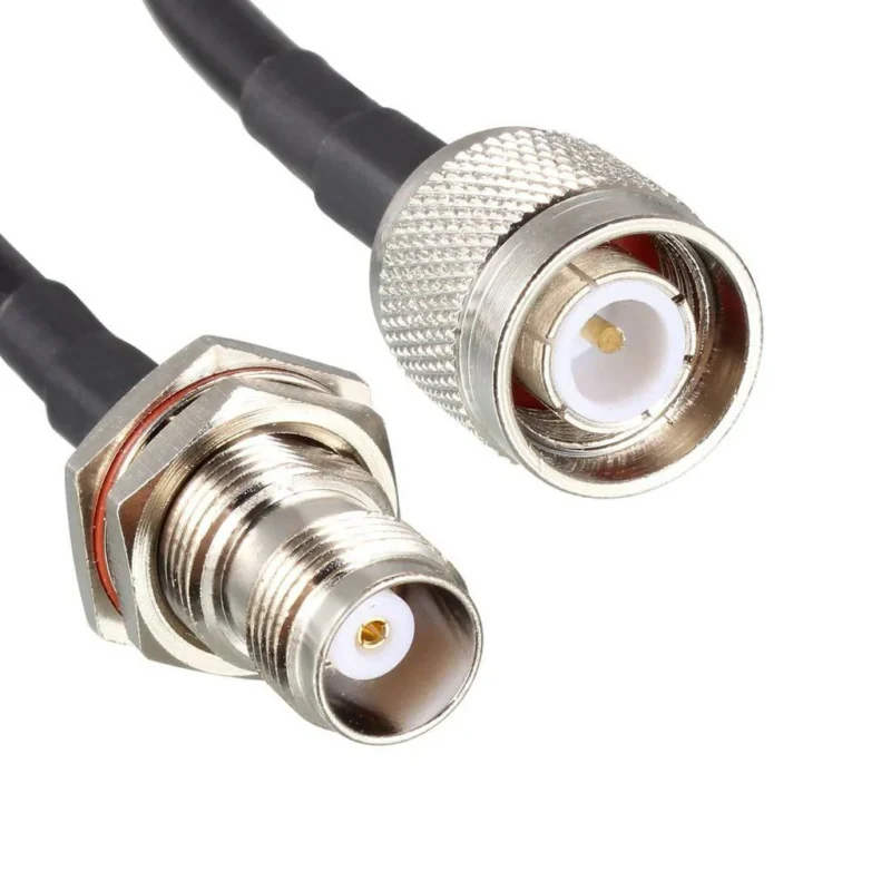
A TNC interface often sits between two very different mechanical environments. Inside the enclosure, a short coaxial jumper or PCB connection may be relatively well protected. Outside, the attached cable can be pulled, bent, twisted, or moved during maintenance.
The TNC connector forms the transition between them. Where that transition is mounted determines how much mechanical stress reaches sensitive RF components.
Define the Equipment-to-Cable Boundary First
Consider an outdoor wireless receiver with a TNC female receptacle mounted through its metal housing. A coaxial feeder connects the equipment to an external antenna.
The RF signal follows a straightforward path:
Typical RF connection path
RF Module / PCB
Internal Coaxial Cable
TNC Panel Interface
Equipment boundary and mounting point
External Coaxial Cable
Antenna / RF Equipment
Electrically, the connection must maintain the specified impedance throughout the assembled RF path. Mechanically, the enclosure should provide a controlled boundary between the external cable and the internal electronics.
A panel-mounted receptacle can serve this purpose when the mounting hardware, panel thickness, and cable support are properly designed. The panel carries the intended connector loads rather than leaving a small PCB-mounted interface to resist external cable movement.
That distinction matters when the external coaxial cable is relatively heavy or stiff. A cable that looks manageable during assembly may apply a significant bending moment once routed around the enclosure.
Keep Cable Torque Away From the Internal RF Module
Imagine an installer connecting a thick coaxial cable to equipment containing a small RF module. The cable initially hangs downward, but its final route requires a sharp change in direction.
If the cable has inadequate strain relief, its stiffness can produce a persistent side load at the TNC interface.
The connector may remain electrically continuous while the mechanical load is transferred into the internal termination or mounting structure. Depending on the assembly, this can contribute to loosening, contact movement, cable damage, or changes in RF measurements.
The solution is not simply to specify a stronger TNC connector.
The cable route and support arrangement must be considered together. For heavier feeders, an appropriately positioned clamp or strain-relief feature can transfer cable weight and bending forces to the chassis.
Engineering reference: External coaxial cables should be supported so that the connector does not carry unnecessary cable weight or bending stress.
Cable flexibility also needs attention. RG316 and RG58 assemblies may require different routing allowances, while larger low-loss coaxial cables can introduce greater installation forces. The exact behavior depends on cable construction, length, bend radius, and how firmly the cable is secured.
For cable selection details, TEJTE’s RG cable guide provides additional background on coaxial construction and application matching.
Separate Mating Torque From Panel-Mount Retention
Two different fastening operations can occur around a panel-mounted TNC connector.
The first is tightening the external mating connector’s coupling nut. This secures the threaded RF interface.
The second is fastening the panel receptacle itself, using a jam nut, flange screws, or another specified mounting arrangement.
These operations should not be treated as interchangeable.
If the panel receptacle is poorly restrained, mating or removing the external connector may rotate the entire receptacle. That rotation can twist an internal coaxial jumper or place stress on a soldered connection.
Engineers should verify the panel mounting arrangement, anti-rotation provision, applicable tightening instructions, and internal cable clearance.
A practical inspection is to mate and remove the actual production cable while observing the fixed receptacle and internal wiring. A connector that remains stable during static inspection may behave differently when the coupling nut is operated.
How Does Threaded Retention Change the Design Compared With BNC?
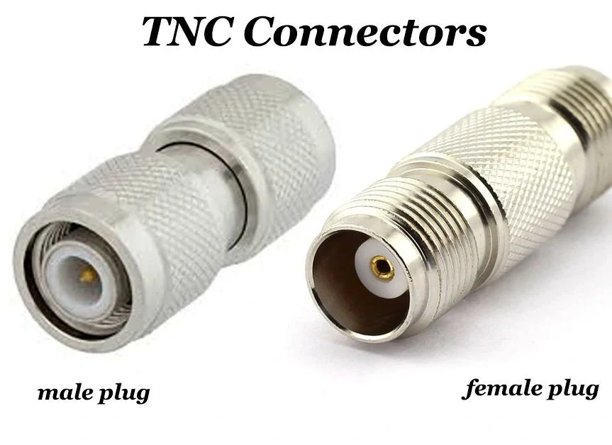
TNC male and female RF connectors shown side by side to help identify connector gender and select the correct mating interface for coaxial cable and equipment connections.
The main mechanical distinction in a TNC vs BNC decision is the coupling method.
A conventional BNC connector uses a bayonet coupling mechanism that supports relatively fast connection and removal. TNC uses a threaded coupling interface, requiring the mating nut to be rotated through its engagement.
That difference changes installation access, service procedures, and retention considerations.
Compare Threaded TNC With Bayonet BNC at the Service Boundary
TNC is often evaluated where mechanical retention is more important than rapid reconnection. Threaded engagement can offer an advantage in applications exposed to movement or vibration, provided the connector is correctly installed and qualified.
BNC may be more convenient for test equipment requiring frequent cable changes.
Evaluate Connection Speed Against Retention Requirements
A production test fixture may be connected and disconnected dozens of times during routine work. In that environment, the extra handling associated with a threaded connector can become inconvenient.
For equipment installed on a vibrating machine or vehicle, connection retention may receive greater priority.
The comparison should be based on actual operating conditions rather than assuming that TNC is universally better.
| Design consideration | TNC | BNC |
| Coupling mechanism | Threaded | Bayonet |
| Frequent manual changes | More rotation required | Generally faster |
| Vibration-sensitive installation | Worth evaluating for retention | Requires application-specific assessment |
| Service access | Space to rotate coupling nut | Space to engage bayonet mechanism |
| Final acceptance | RF and mechanical verification | RF and mechanical verification |
This comparison addresses interface mechanics, not the full electrical capability of every connector variant. Frequency limits, impedance, return loss, and durability must still be checked against the selected part number.
Check Tool and Finger Clearance Around the Coupling Nut
A threaded connector needs enough surrounding space for installation. This becomes easy to overlook when multiple RF ports are arranged closely on a compact equipment panel.
Two TNC receptacles may fit within the enclosure drawing, yet the spacing may prevent technicians from gripping or rotating the mating coupling nuts.
The mating connector’s outside diameter is not the only relevant dimension. Engineers should also check the coupling nut diameter, required tightening-tool clearance, cable exit direction, and minimum permitted bend radius.
Engineering reference: Closely spaced RF ports require sufficient coupling-nut access and cable-routing clearance.
A useful approach is to check the panel layout with the actual mating cable assembly installed, rather than relying only on receptacle dimensions.
For production equipment, connector spacing should accommodate the approved installation procedure. If the selected connector requires a torque wrench, the tool must have sufficient access to engage the coupling nut without contacting adjacent components.
Mechanical access should be verified before the panel drawing is released. Correcting connector spacing after enclosure tooling is completed can be considerably more expensive than addressing it during the initial layout.
Which TNC Gender Belongs on the Equipment and Cable?
A surprisingly common purchasing error starts with a short description such as “TNC male connector” or “TNC female connector.” That identifies the mating interface, but it does not tell the supplier how the connector is mounted or what happens behind it.
For an equipment interface, start with the fixed port.
If the enclosure already uses a TNC female connector, the external cable normally needs the corresponding standard-polarity TNC male interface. But the specification should go further. Is the female connector a jam-nut bulkhead receptacle, a four-hole flange receptacle, a cable-mounted connector, or a feedthrough?
Those parts may present a similar front interface while requiring completely different mechanical installation.
Identify the Fixed Equipment Port Before Ordering the Mating Cable
For example, an outdoor radio may use a fixed TNC female bulkhead receptacle. The external antenna cable then requires a compatible male connector, but that male connector must also fit the selected coax.
A male plug intended for one cable construction should not automatically be substituted for another simply because the front end mates correctly.
This is where BOM descriptions such as “TNC cable” become risky. They leave too many variables open.
The exact frequency requirement, plating, environmental requirements, and inspection criteria can then be added according to the project.
Separate Cable Plugs From Panel Receptacles
Gender alone does not define mounting role.
A TNC female connector might be supplied as a cable-end socket, jam-nut bulkhead receptacle, flange-mounted receptacle, or another fixed-interface design. Likewise, a male interface can appear on cable assemblies or specialized equipment hardware.
Procurement teams should therefore confirm four items together:
| Item to Specify | What Must Be Defined |
| Connector family | TNC |
| Interface gender | Male or female |
| Center contact | Pin or socket according to specified polarity |
| Mechanical role | Cable, bulkhead, flange, feedthrough, or other mount |
If naming becomes ambiguous, use the mechanical drawing. A dimensioned drawing usually resolves questions that words such as “TNC head,” “antenna connector,” or “panel TNC” do not.
How Should the Rear Body Match the Coax Cable?
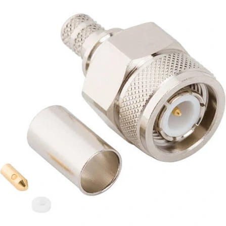
Exploded view of a TNC crimp connector showing the connector body, ferrule, dielectric, and center contact. Correct component and cable matching helps ensure mechanical retention and stable RF performance.
The front interface receives most of the attention because it is visible. The rear body is where many production problems actually begin.
A TNC RF connector designed around one cable diameter and dielectric structure may not terminate correctly onto another cable, even if both cables are nominally 50 ohm.
RG58, RG316, and larger low-loss cables differ substantially in physical construction. Cable OD is only the first check.
Verify the Exact Cable Before Selecting the Rear Termination
The connector drawing or supplier data should be checked against the actual cable specification.
For a crimp-style assembly, relevant dimensions can include:
- overall cable diameter;
- dielectric diameter;
- center conductor diameter;
- braid or shield construction;
- ferrule inside diameter;
- rear cable-entry diameter;
- recommended strip dimensions.
The cable manufacturer and connector supplier may use similar generic cable names while actual dimensions differ slightly. Those differences matter when the production process depends on controlled crimp compression and correct dielectric support.
A loose ferrule can produce inadequate braid retention. An undersized ferrule can damage the jacket or make assembly inconsistent. A center contact that does not match the conductor diameter may create poor retention or soldering problems.
These are assembly issues first, but they can become RF issues later.
A cable may still pass DC continuity while showing unstable return loss after bending or vibration.
Choose Crimp, Clamp, or Solder From the Connector Design
Termination method should follow the approved connector-and-cable combination rather than operator preference.
A connector designed for crimping should be assembled using the specified ferrule and suitable tooling. A clamp-style connector has a different mechanical approach. Some designs use solder for the center conductor while the outer conductor is crimped or clamped.
Mixing procedures because “it looks close enough” is a poor production strategy.
The safest sourcing rule is to freeze the connector part number and cable part number as a qualified pair after sample approval.
If the cable changes later, even to another nominally equivalent 50-ohm coax, review the rear termination again.
For broader cable construction considerations, the TEJTE RG Cable Guide can be used when comparing cable diameter, flexibility, shielding, and application requirements.
How Should a Panel-Mounted TNC Port Be Supported?
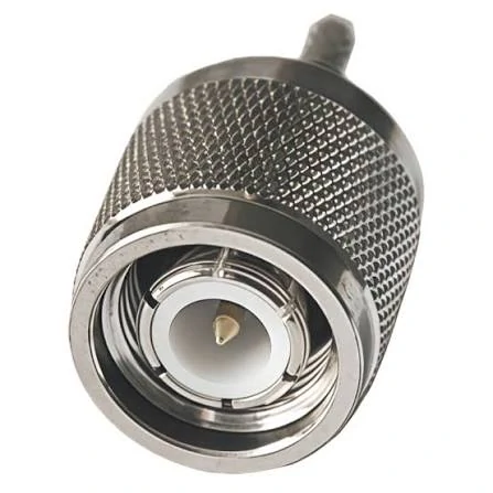
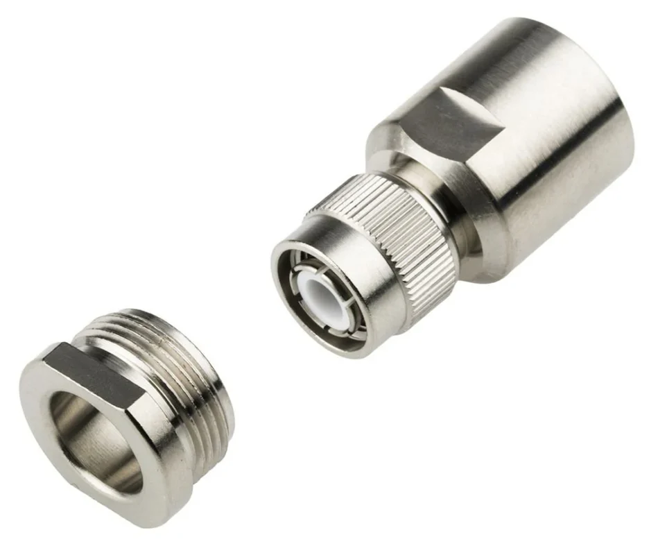
TNC male coaxial connector with a threaded coupling mechanism designed for secure RF connections where retention, vibration resistance, and reliable mating are important.
A TNC bulkhead connector has two jobs. It must maintain the RF interface, and it must remain mechanically stable in the enclosure.
The panel therefore becomes part of the connector installation.
Design the Cutout From the Exact Connector Drawing
Do not design the enclosure hole from a catalog photograph or a generic TNC dimension.
Check the actual part drawing for:
- mounting-hole diameter;
- anti-rotation flats or keying;
- shoulder dimensions;
- jam-nut and washer arrangement;
- flange-hole pattern;
- usable panel-thickness range;
- rear clearance.
A panel that is too thick can prevent proper nut engagement. A hole that is too large may reduce anti-rotation control. Incorrect washer or sealing hardware can also change how the connector sits against the enclosure.
Prevent the Connector From Rotating During Mating
Every time an external TNC cable is screwed onto the equipment, torque is applied to the fixed port.
If the receptacle turns with the coupling nut, that torque can move into the internal cable.
Heavy or stiff external cable should ideally be supported before its full weight and bending force reach the connector.
A practical first-article check is simple: install the production mating cable, tighten it using the approved procedure, route it in the actual direction, then inspect the receptacle and internal cable for rotation, twisting, or excessive bending.
Finally, verify RF behavior in the installed condition. Bench measurements with the connector lying freely on a table cannot reproduce every mechanical condition created by the enclosure.
The most useful production approval is therefore not “the TNC connector fits.” It is the specified connector, cable, panel geometry, and assembly process work together as one qualified interface.
When Should TNC Convert to BNC or SMA?
Not every RF system uses the same connector at both ends. A rugged equipment enclosure may use TNC, while the test instrument, RF module, or existing field cable uses BNC or SMA.
That makes an adapter necessary, but the adapter should be treated as another RF and mechanical transition—not simply as a piece of hardware that changes the connector shape.
A TNC to BNC adapter can make sense when equipment must connect to existing BNC-based test leads or legacy field infrastructure. The reverse arrangement, using a BNC to TNC adapter, solves the same interface problem from the other direction.
The first checks are still impedance, gender, polarity, frequency range, and installation geometry.
Use TNC-to-SMA for Compact RF Modules and Test Ports
SMA commonly appears on compact RF modules, test instruments, PCB assemblies, and smaller coaxial cables. TNC is physically larger and may be better suited to the external equipment boundary where threaded retention is desired.
A direct TNC to SMA adapter works when both ports are aligned and mechanically supported.
If the ports are separated, offset, or exposed to vibration, a short flexible cable assembly is often easier to manage.
Rigid adapters deserve extra attention when attached to a panel port because they increase leverage. Adding another adapter behind that can create a long unsupported connector stack.
Each transition can also contribute some combination of:
- insertion loss;
- reflection;
- additional mating interfaces;
- mechanical leverage;
- maintenance points.
The exact RF penalty depends on the parts and operating frequency, so avoid assigning a universal loss value to every adapter.
How Can You Verify TNC Reliability After Vibration or Re-Mating?
A connector that still looks tight after vibration has not automatically passed RF qualification.
Start with mechanical inspection. Check the threads, coupling mechanism, dielectric, center contact, panel retention, cable entry, and any evidence of movement around the rear termination.
Then compare measurements.
For a complete cable assembly, S21 or insertion loss can also be useful.
Static continuity is not enough. A poor braid connection or partially damaged center contact can remain electrically continuous while the RF response changes.
One practical check is to flex the cable near the connector while observing the electrical or RF result. Intermittent behavior during movement deserves investigation even when the assembly passes while lying still.
Do not invent a universal TNC pull-force, mating-cycle, or VSWR acceptance number. Those limits should come from the selected connector specification, customer requirement, or project qualification plan. The attached article plan specifically treats acceptance limits as project-dependent rather than applying one number to every TNC connector.
How Can You Qualify a TNC Equipment Interface?
Connector approval becomes easier when mechanical and RF requirements are checked together instead of being split between unrelated drawings, emails, and supplier notes.
The following matrix can be used as a first-article or sourcing review tool.
| Verification Field | Engineering Input | Pass Rule |
| Connector role | Cable / panel / bulkhead | Exact role confirmed |
| Gender | Male / female | Correct mating pair |
| Impedance | System requirement | Match |
| Cable | Exact cable PN | Approved fit |
| Termination | Crimp / clamp / solder | Process confirmed |
| Panel mounting | Hole / flange / nut | Drawing matches |
| Cable load | Weight and routing | Properly supported |
| Frequency | Operating band | Rated range covers it |
| RF test | VSWR / return loss / S21 | Project limit passed |
| Environment | Vibration / re-mating | Requirement passed |
This reflects the qualification logic defined in the article outline: gender, impedance, cable fit, mechanical fit, frequency, RF verification, and environmental requirements act as hard gates rather than interchangeable scoring items.
FAQ
Can a TNC connector be electrically correct but mechanically wrong?
Yes. Impedance and frequency may be correct while cable weight, panel thickness, bend direction, mounting clearance, or connector retention makes the installed configuration unsuitable.
Why can a TNC cable pass continuity but fail after vibration?
Continuity only verifies an electrical path. It does not prove stable shield contact, center-contact position, impedance, or RF behavior while the cable and connector are moving.
Can a TNC female cable connector replace a female bulkhead receptacle?
Usually not as a direct substitute. The mating interface may be similar, but the mounting hardware, rear termination, mechanical load path, and intended installation are different.
Should TNC always replace BNC where vibration exists?
No. Threaded retention can be useful, but service requirements, installation space, frequency, cable design, and actual environmental qualification still determine the better interface.
Is a TNC-to-SMA cable better than a rigid adapter?
It can be when ports are offset, separated, or mechanically sensitive. A rigid adapter is more appropriate when alignment is controlled and both interfaces are adequately supported.