
A TNC cable can look correct in a product photo and still be the wrong part for the job.
The thread fits. The center contact appears normal. The connector mates with the equipment port. Then the problem shows up after installation: VSWR moves when the cable is touched, the radio drops signal during vibration, or the same assembly gives different readings after several re-mates.
That is where a tnc connector should be judged carefully. Its value is not only that it resembles a BNC connector with threads. The useful point is the mating security, especially in antenna systems, mobile radios, field equipment, industrial wireless devices, and RF test setups where a loose bayonet connection would create too much uncertainty.
A good TNC choice starts with three questions: will the interface stay mechanically stable, does the connector actually match the cable, and can the assembly be verified at the working frequency? If any one of those is skipped, the connector may still pass continuity while failing as an RF part.
How Does a TNC Connector Improve RF Connection Stability?
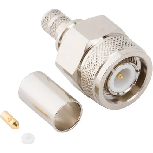
Detailed view of TNC cable connector components before assembly. The precision structure helps maintain correct impedance matching, reliable cable termination, and consistent RF performance when installed with compatible coaxial cables.
A TNC connector is usually chosen because the connection needs to stay locked. The threaded coupling gives the interface more resistance to vibration, handling movement, cable pull, and accidental rotation than a quick bayonet-style connector.
That difference matters most after the first bench test. On a clean bench, even a marginal connection may seem acceptable. The cable is straight, the device is still, and the operator is not stressing the assembly. In the field, the cable may be routed around a bracket, tied to a moving panel, or pulled sideways by its own weight. A weak mating interface can then become an RF fault.
The symptoms are not always dramatic. A loose or unstable RF connection may cause:
- intermittent signal loss
- changing VSWR
- unstable return loss
- repeatability problems during testing
- faster connector wear
- failure that appears only after vibration or re-mating
A continuity meter will not catch most of these problems. It can confirm that the center conductor is connected and that the shield is not open, but it does not tell you whether the connector interface behaves well at RF frequency.
Threaded coupling is useful when the equipment moves
For mobile radio systems, antenna installations, telemetry equipment, and outdoor wireless devices, the connector is part of the mechanical design. It is not only an electrical termination.
A TNC interface can help when the assembly is exposed to:
- vehicle vibration
- repeated handling
- cable routing stress
- enclosure movement
- field installation errors
- antenna mast or panel movement
This does not mean every TNC connector is automatically suitable for every rugged system. The cable termination, crimp quality, solder joint, ferrule size, strain relief, and panel mounting method still matter. A strong front interface cannot rescue a poor rear termination.
One common sourcing mistake is selecting the front interface correctly but ignoring the cable side. A TNC plug for RG58 may not fit RG316. A connector body made for a larger dielectric may not hold a smaller cable correctly. The assembly may look acceptable, but braid contact, center pin position, and crimp retention can be wrong.
TNC sits between BNC and larger threaded RF interfaces
A practical way to think about TNC is to place it between BNC and larger connectors such as N Type.
BNC is fast. It is convenient on test benches, older instruments, video equipment, and temporary setups where frequent connection and disconnection matters. The trade-off is that the bayonet lock is not ideal for vibration-heavy use.
TNC keeps a similar general size class but replaces the quick bayonet connection with a threaded interface. That makes it more suitable for applications where the cable should not loosen during use.
N Type is larger and often used for outdoor antenna feeds, higher-power RF paths, and heavier cable assemblies. It gives strong mechanical support, but it also takes more space and may be unnecessary for compact equipment.
| Interface | Locking Style | Typical Fit | Main Risk if Misused |
| BNC | Bayonet quick lock | Bench testing, video, temporary RF setups | Can loosen or vary under vibration |
| TNC | Threaded coupling | Mobile RF, antennas, rugged instruments | Wrong cable termination can still cause failure |
| N Type | Larger threaded interface | Outdoor feed lines, higher-power RF paths | May be too large for compact equipment |
The connector choice should follow the actual installation. If the cable will stay in a fixed lab setup and be changed often, BNC may be easier. If the equipment may vibrate, move, or be handled in the field, TNC usually deserves a closer look.
How Do You Identify TNC Male and Female Connectors Correctly?
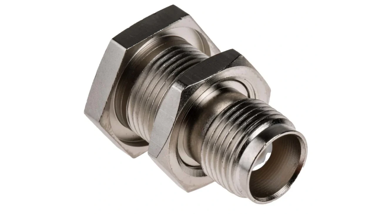
Do not identify TNC gender only by the outer shell.
That mistake causes wrong orders, especially when buyers are working from catalog photos, panel drawings, or customer screenshots. The safer method is to check the center contact first.
A standard TNC male connector usually has a center pin. A standard TNC female connector usually has a center socket. The outer thread or coupling nut helps confirm the mechanical style, but the center contact is the first thing to check.
This is especially important when ordering cable assemblies. A buyer may say “TNC connector” while meaning any of these:
- TNC male cable plug
- TNC female cable jack
- TNC bulkhead connector
- TNC panel mount connector
- TNC right-angle connector
- TNC to BNC adapter
- TNC to SMA adapter
- reverse-polarity TNC version
A wrong gender selection is not a small paperwork issue. It can stop installation completely.
Cable plug, panel jack, and bulkhead styles are not interchangeable
TNC connectors may share the same front interface but serve different mechanical jobs.
A cable-end TNC connector terminates coaxial cable. A panel mount version fixes the RF interface to equipment housing. A bulkhead connector passes through a panel and is often secured with a nut and washer. A flange mount version uses screw holes to fix the connector to a surface.
For procurement, “TNC female” is not enough. A TNC female bulkhead connector and a TNC female cable connector may mate with the same male plug, but they are not the same part.
Use a requirement line like this:
50 ohm TNC female bulkhead connector, straight type, panel mount, DC–6 GHz requirement, for antenna enclosure installation.
That is far better than:
TNC head, female.
The second version leaves too many decisions to the supplier. It may still get quoted, but the risk of receiving the wrong style is much higher.
Confirm the mating direction before ordering assemblies
Before ordering a TNC cable assembly, confirm both ends of the RF path.
The equipment port may be female, so the cable end likely needs to be male. But adapters, antenna bases, test instruments, and enclosure feedthroughs can reverse that assumption. A photo is helpful, but a photo without center-contact visibility can still mislead.
A clean TNC requirement should include:
- equipment port gender
- cable-end gender
- straight or right-angle body
- standard or reverse polarity
- cable type and length
- impedance
- frequency range
- installation environment
- test requirement if needed
If the assembly will be used in a vibration-prone system, also confirm whether the cable needs extra strain relief. The threaded interface may stay tight, but the cable can still fail behind the connector if it is bent sharply or pulled sideways.
How Should You Choose a TNC Connector for Coax Cable?
The cable side decides whether the connector can be assembled correctly.
A TNC connector for RG58, RG174, RG316, RG142, RG400, or an LMR-series cable may use a different rear body, ferrule, dielectric support, center pin, or attachment method. The front interface may still be TNC, but the cable fit is different.
This is where many RF purchasing errors happen. The buyer selects the interface and gender, then assumes the supplier can “make it fit” to the cable. Sometimes it can be adapted. Sometimes it should not be.
For short RF patch leads, RG58 is common. For compact assemblies, RG174 or RG316 may be more suitable. For higher-temperature or better-shielded lab assemblies, RG142 or RG400 may be considered. For longer antenna feeds, low-loss cable families may be better, but only when a compatible TNC connector style is available.
A practical review should include the cable OD, dielectric size, braid structure, crimp sleeve, soldering method, and strain relief. If those are not controlled, two assemblies with the same “TNC male” description may perform differently.
| Cable Factor | Why It Matters for TNC Selection | Buyer Action |
| Cable type | Determines rear body and center pin fit | Specify RG / LMR type clearly |
| Cable OD | Affects ferrule and strain relief | Provide diameter if cable is non-standard |
| Dielectric size | Affects center contact alignment | Avoid substituting similar-looking cables |
| Braid structure | Affects crimp and shield contact | Confirm crimp or solder method |
| Frequency requirement | Cable may limit performance before connector | Test assembly near working band |
| Installation stress | Bending can damage termination | Add strain relief if needed |
A TNC coax connector should not be selected from appearance alone. The right part is the one that fits the cable mechanically and supports the RF requirement electrically.
How Does TNC Compare With BNC in RF Applications?
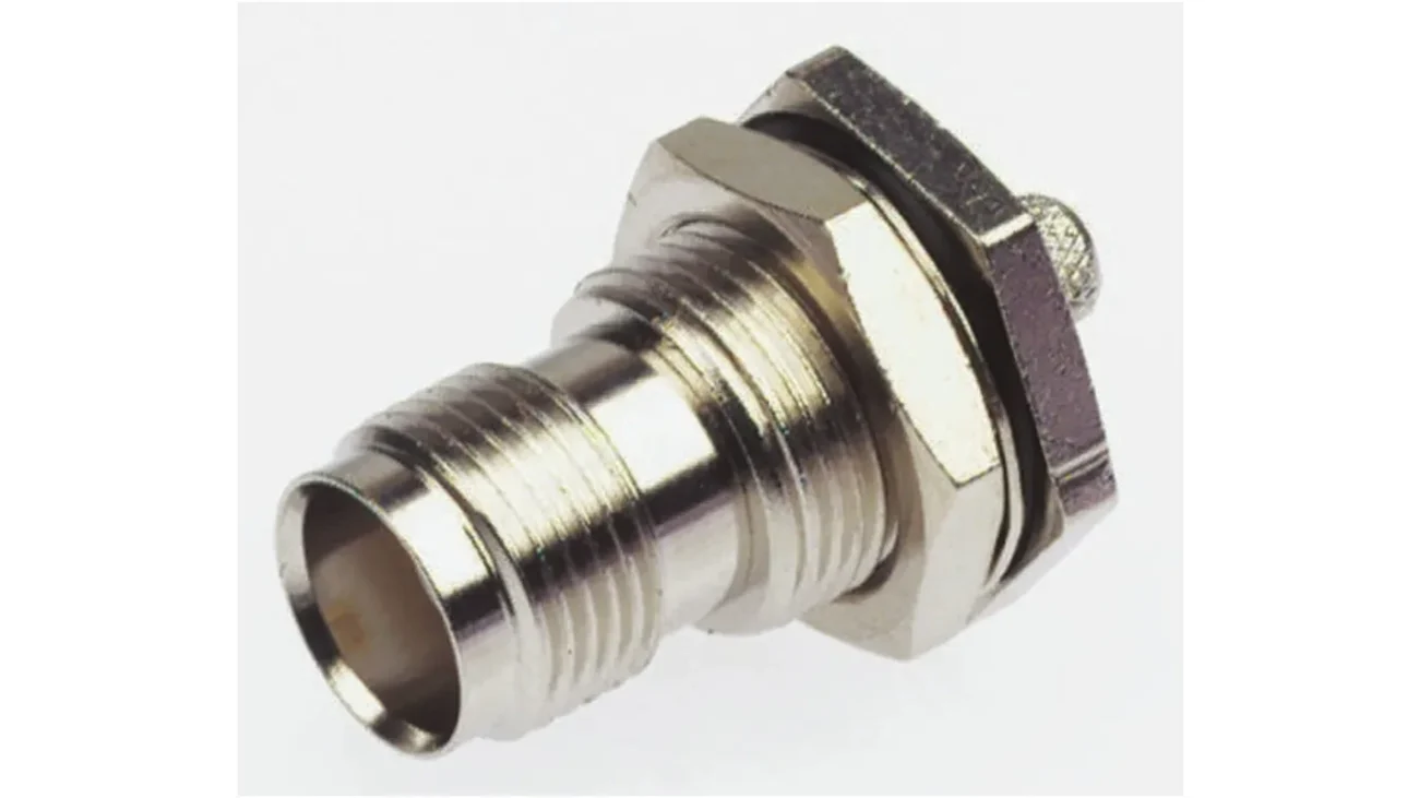
The usual shortcut is to say that TNC is the threaded version of BNC. That is not wrong, but it is not enough for selection.
The real question is what kind of connection behavior the system needs. If the connector is used on a bench instrument and is connected many times a day, BNC is convenient. If the same connection is on a vehicle radio, outdoor antenna cable, industrial controller, or vibration-prone enclosure, TNC becomes the safer interface.
BNC uses a bayonet quick-lock structure. It is fast, simple, and familiar in test labs. TNC uses threaded coupling. It takes longer to mate, but it gives a firmer mechanical connection. That trade-off is the main reason both interfaces continue to exist.
| Selection Question | If Yes | Better Starting Point |
| Need frequent fast connection on a bench? | Yes | BNC |
| Equipment may vibrate during use? | Yes | TNC |
| Used mainly for oscilloscope or video work? | Yes | BNC |
| Threaded antenna connection required? | Yes | TNC |
| Cable will be installed once and left in place? | Yes | TNC |
| Test setup changes many times per day? | Yes | BNC |
| Higher-frequency stability matters more than speed? | Yes | Review TNC specification |
This table is not a universal rule. It is a selection filter. The exact connector still depends on impedance, frequency rating, cable type, mounting style, and test requirement.
Choose BNC when fast bench connection matters
BNC is useful when the operator needs speed.
A test engineer working with oscilloscopes, signal generators, older RF instruments, or temporary video systems may prefer BNC because it connects quickly. It is also easier to rotate and remove in cramped bench setups.
That convenience has value. Not every RF connection needs a threaded interface. If the setup is temporary, low stress, and changed often, TNC may simply add time without solving a real problem.
The trap is using that same logic in the field. A connector that feels convenient during prototype testing may become unstable after the product is installed in a vehicle, cabinet, antenna bracket, or moving assembly.
Choose TNC when vibration or mating repeatability matters
TNC is usually the better candidate when the connector should stay fixed after installation.
Typical examples include:
- vehicle-mounted radios
- wireless antenna feeds
- rugged test instruments
- outdoor RF equipment
- telemetry systems
- industrial wireless devices
- field communication devices
A threaded connector also gives the installer a clearer sense of completion. The coupling nut is tightened, the interface is seated, and the cable is less likely to loosen from casual handling.
That does not mean over-tightening is acceptable. Damaged threads, crushed dielectric, bent center contacts, or worn plating can still create poor RF behavior. For sensitive test leads, repeated mating should be treated as a wear factor, not ignored.
When Should You Use a TNC to BNC or TNC to SMA Adapter?
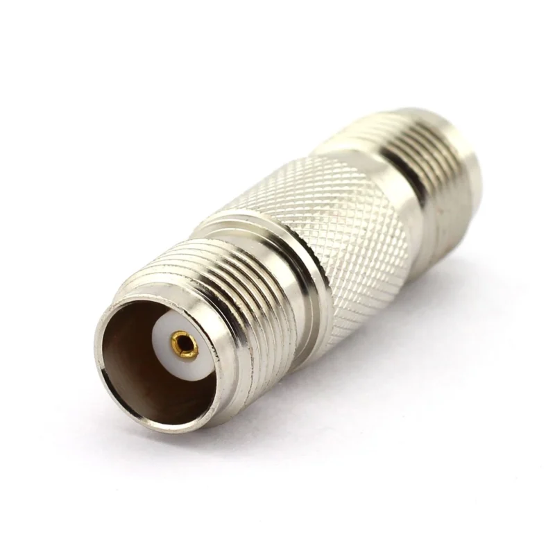
Adapters are useful. They are also easy to overuse.
A TNC to BNC adapter can help connect a TNC antenna cable to a BNC instrument. A TNC to SMA adapter can connect a threaded antenna interface to a compact RF module. For development work, troubleshooting, or low-volume integration, that flexibility is often necessary.
The problem appears when adapters become a permanent fix for a poorly specified cable assembly. Every added interface brings another mating surface, another possible reflection point, and another mechanical leverage point.
Use TNC to BNC adapters for lab and legacy equipment transitions
A TNC to BNC adapter is common when the device and the instrument do not share the same interface.
Typical cases include:
- TNC antenna cable to BNC test instrumen
- BNC signal source to TNC RF device
- temporary measurement setup
- legacy equipment connection
- quick troubleshooting before ordering a final assembly
For short-term use, this is reasonable. The adapter allows testing to continue without rebuilding the cable immediately.
For production, it is better to ask whether a direct cable assembly would be cleaner. A TNC-to-BNC cable can remove one adapter interface, reduce mechanical length, and simplify the BOM.
Use TNC to SMA adapters for compact RF modules and antennas
SMA appears often on compact RF modules, wireless boards, development kits, and small antennas. TNC appears more often where a larger threaded interface is useful for external antenna connection or field equipment.
A TNC to SMA adapter can bridge those two worlds.
Use it carefully when:
- connecting a TNC antenna to an SMA module
- testing a wireless board with a TNC antenna cable
- adapting compact RF hardware to field antenna infrastructure
- building a temporary validation setup
The mechanical side needs attention. SMA is smaller. A heavy TNC cable hanging from an SMA port through an adapter can stress the module connector. In that case, a short flexible adapter cable may be safer than a rigid adapter.
Avoid stacked adapters when a custom cable is cleaner
One adapter is often acceptable. Two or three adapters in a row should trigger a review.
A stacked adapter chain can create:
- extra insertion loss
- additional mismatch points
- longer mechanical leverage
- more mating uncertainty
- harder troubleshooting
- higher risk during vibration
A simple RF path penalty check helps buyers decide whether the adapter chain is getting too messy.
RF Path Interface Count = Connector Interfaces + Adapter Interfaces + Cable Terminations
Use this as a practical review rule:
| RF Path Interface Count | Risk Level | Recommended Action |
| 2–3 | Low | Usually acceptable if frequency and VSWR are not demanding |
| 4–5 | Medium | Review adapter count and test the full path |
| 6 or more | High | Consider a custom cable assembly or simplified interface plan |
This is not a formal RF formula. It is a sourcing control. The more interfaces in the path, the more likely the real assembly will behave differently from the drawing.
How Do Frequency Range and Impedance Affect TNC Selection?
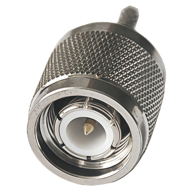
This TNC male connector is designed for reliable coaxial signal transmission with a precision RF interface. The threaded coupling mechanism improves connection stability compared with bayonet-style connectors, making it suitable for mobile communication systems, industrial RF equipment, and outdoor antenna applications.
A TNC connector should not be selected only by name.
Standard TNC connectors are often associated with RF use into the GHz range, but the actual limit depends on the connector design, impedance, dielectric, cable match, assembly quality, and supplier specification. A cable assembly rated for one frequency does not automatically perform well across every installation condition.
The cable may become the bottleneck before the connector does.
For example, a short TNC assembly made with a suitable low-loss cable may behave well at a target band. A longer assembly using a smaller or lossier cable may show more insertion loss even if the connector interface is technically rated high enough.
Check frequency rating before assuming all TNC versions are equal
Frequency rating should be checked at the connector and assembly level.
A buyer should ask:
- What is the connector’s rated frequency?
- Is the rating for the connector alone or the assembled cable?
- What cable type is used?
- What is the cable length?
- How many adapters are included?
- What VSWR or return loss is expected at the target frequency?
If the supplier only confirms “TNC connector” without the test band, that is not enough for RF purchasing.
A useful margin check is:
Frequency Margin Ratio = Connector or Assembly Rated Frequency ÷ Highest Operating Frequency
| Frequency Margin Ratio | Practical Meaning | Suggested Use |
| Below 1.0× | Not enough | Do not use without redesign |
| 1.0×–1.2× | Tight margin | Test carefully at the working band |
| 1.2×–1.5× | Moderate margin | Often acceptable for general RF links |
| Above 1.5× | Better margin | Safer for test setups or stricter VSWR targets |
This margin does not replace testing. It simply prevents obvious under-selection before the order is placed.
Match TNC impedance with the complete RF chain
Most RF TNC applications are 50 ohm, but impedance should still be confirmed. The connector, cable, adapter, antenna, load, and instrument should belong to the same RF system design.
A mismatch may not stop the connection from physically mating. It may not even fail a continuity test. The problem shows up as reflected power, unstable readings, poor antenna behavior, or measurement error.
For a TNC assembly, confirm:
- connector impedance
- coaxial cable impedance
- adapter impedance
- antenna or load impedance
- instrument port impedance
- expected VSWR or return loss
Do not mix parts casually because the thread fits. RF compatibility is not the same as mechanical compatibility.
Verify performance with VSWR or return loss when frequency rises
For low-risk applications, visual inspection and continuity testing may be enough to catch basic assembly mistakes. For higher-frequency or measurement-sensitive systems, RF testing becomes more important.
Useful checks include:
- S11
- VSWR
- return loss
- insertion loss
- center-to-shield short test
- shield continuity
- repeated mating check if the assembly is used as a test lead
The final question is simple: does the assembly behave correctly at the frequency where it will actually be used?
That is the point many purchase descriptions miss. A complete RF request should not only say “TNC male cable.” It should say what the cable connects, what frequency it works at, what cable type is required, and how the finished assembly should be accepted.
How Should You Select TNC Connectors for Antenna Systems?
Antenna systems are where TNC connectors often make sense. The connection may sit outside a cabinet, near a vehicle body, on a mast, inside an RF enclosure, or between a radio and an external antenna cable. In those places, the connector is exposed to more than signal current.
It sees cable weight, vibration, bending, weather, panel stress, repeated service work, and sometimes installers who are working quickly.
A TNC antenna connector should be selected by the full installation, not only by the antenna port. Start with the mating interface, then check cable type, routing, strain relief, mounting style, and environmental exposure.
Match antenna ports with the correct TNC interface
Antenna equipment may use TNC male, TNC female, bulkhead TNC, panel mount TNC, or reverse-polarity TNC. Do not assume the connector type from the antenna body alone.
Confirm the center contact. Then confirm the thread, mounting method, and polarity.
For antenna systems, TNC is commonly found in:
- vehicle-mounted antennas
- GPS and telemetry devices
- wireless radio equipment
- rugged handheld or field communication devices
- RF enclosures with external antenna ports
- industrial wireless systems
If the antenna cable will be removed often, check mating wear. If it will be left installed, check whether the cable can be fixed so the connector does not carry bending load.
Consider cable strain, routing, and field installation
Many antenna failures are not caused by the front connector interface. They start behind the connector.
A cable may be bent too close to the rear body. A tie wrap may pull the cable sideways. A panel connector may be tightened unevenly. A right-angle adapter may be used because the enclosure is crowded, but it may also create extra stress on the port.
Review these details before ordering:
| Installation Factor | Why It Matters | Recommended Check |
| Cable bend radius | Sharp bends can damage braid or dielectric | Keep routing smooth behind the connector |
| Panel thickness | Bulkhead threads may not have enough engagement | Confirm panel range before ordering |
| Cable weight | Heavy cable can pull on the interface | Use strain relief or bracket support |
| Outdoor exposure | Moisture can enter through poor sealing | Check gasket, boot, or waterproof version |
| Vibration | Loose routing can fatigue the termination | Fix the cable near the connector |
| Service access | Tight spaces cause over-bending during removal | Leave tool and hand clearance |
This is why a smaller connector is not always better. SMA is compact and useful for small RF modules, but TNC can be the better field interface when threaded mating and handling strength are more important than minimum size.
How Can You Test TNC Connector Assemblies Before Installation?
A TNC cable assembly should not go straight from unpacking to final installation if the application is sensitive to RF behavior.
Start with a visual check. It sounds basic, but it catches many avoidable failures before test equipment is needed.
Look for damaged threads, loose coupling nuts, bent center pins, recessed sockets, cracked dielectric, plating damage, poor crimp shape, and cable jacket cuts. If the connector is a bulkhead style, check the nut, washer, gasket, and mounting shoulder.
Measure continuity before RF testing
Continuity testing is not enough, but it is still the first electrical filter.
Check:
- center conductor continuity
- shield continuity
- center-to-shield short
- obvious open circuit
- intermittent contact while gently moving the cable
If the cable fails here, do not continue to RF testing. Fix the basic assembly issue first.
A part can pass continuity and still fail at RF frequency. That point matters for TNC assemblies used near the upper working band, in test equipment, or in antenna systems where VSWR affects transmitter behavior.
Verify RF behavior across the required band
For higher-frequency systems, use RF testing that matches the real working range. A VNA sweep can show issues that visual inspection cannot confirm.
Useful parameters include:
- S11
- return loss
- VSWR
- insertion loss
- S21
- re-mate repeatability
Do not test only at a convenient low frequency if the cable will operate much higher. The test should cover the actual band or at least the highest important operating point.
TNC Connector RF Acceptance Matrix
Use this matrix as a practical acceptance record for incoming inspection or supplier confirmation.
| Parameter | Record |
| Connector Gender | Male / Female |
| Mounting Style | Cable / Panel / Bulkhead / Flange |
| Cable Type | RG58 / RG174 / RG316 / RG142 / RG400 / LMR series |
| Impedance | 50Ω / other confirmed value |
| Frequency Range | MHz / GHz |
| S11 / Return Loss | dB |
| VSWR | Value at target frequency |
| Insertion Loss | dB |
| Re-mate Repeatability | Pass / Fail |
| Visual Inspection | Pass / Fail |
| Final Result | Accept / Reject |
This matrix is useful because it forces the buyer and supplier to define what “qualified” means. Without it, many RF orders are accepted based only on mating fit and cable length.
How Do You Specify the Right TNC Connector for Quotation?
A vague request creates a vague quote.
“Need TNC connector” may be enough for a conversation, but it is not enough for purchasing. A supplier still has to guess gender, cable type, body style, impedance, frequency rating, termination method, and application conditions.
A better request looks like this:
50Ω TNC male connector for RG58 cable, straight crimp style, DC–6 GHz requirement, gold-plated contact, PTFE insulator, for vibration-resistant antenna cable assembly.
That sentence gives the supplier enough information to check fit and performance. It also reduces the chance of receiving a connector that mates at the front but fails at the cable side.
Confirm the RF and mechanical requirements before asking for price
Before requesting quotation, prepare these fields:
- connector gender
- standard or reverse polarity
- impedance
- cable type
- cable length if assembly is needed
- straight or right-angle body
- cable mount, bulkhead, panel mount, or flange mount
- frequency range
- plating requirement
- attachment method
- application environment
- quantity
- inspection requirement
For custom assemblies, add drawings or photos of the equipment port. If a previous part failed, include the failure symptom. “VSWR unstable after vibration” is more useful than “connector quality problem.”
Avoid vague names like “TNC head” or “antenna connector”
Different companies use different casual names. “TNC head,” “TNC terminal,” “antenna connector,” and “RF connector” may all appear in purchase messages, but they do not define the part.
The common errors are predictable:
| Vague Request | Possible Mistake |
| TNC head | Gender unclear |
| TNC cable connector | Cable type unclear |
| TNC antenna connector | Standard polarity or RP-TNC unclear |
| TNC panel connector | Bulkhead, flange, or panel style unclear |
| TNC adapter | Transition direction unclear |
| TNC for RG cable | Exact RG cable type unclear |
A clean BOM line prevents most of this.
Example BOM note:
TNC male plug, 50Ω, straight cable type, for RG58 coaxial cable, crimp termination, DC–6 GHz target use, gold-plated center contact, PTFE insulator, VSWR check at operating band.
That level of detail is not excessive. It is the difference between buying a connector and buying the correct RF assembly.
Why Are TNC Connectors Still Used in Modern RF Equipment?
TNC remains useful because many RF systems still need a medium-size threaded interface.
BNC is fast, SMA is compact, and N Type is stronger for larger outdoor feed systems. TNC sits in the space between them. It gives better mating security than BNC, more handling comfort than SMA in some field connections, and a smaller footprint than N Type.
That position is still valuable.
TNC supports rugged RF links in mobile and wireless systems
TNC connectors continue to appear in mobile communication, antenna feed lines, industrial wireless systems, rugged instruments, and military-style radio equipment. The reason is not nostalgia. The interface solves a practical connection problem.
A threaded connector helps when the cable may move after installation. It also helps when service technicians need a connector that is more secure than bayonet locking but not as large as N Type.
Mixed RF systems still need adapter and cable options
Modern RF equipment often mixes interfaces. A test instrument may use BNC. A wireless module may use SMA. An antenna enclosure may use TNC. A heavier feed line may use N Type.
That does not mean adapters should be stacked without review. It means buyers should plan the RF path early.
A direct TNC cable assembly is usually cleaner than forcing several adapters into the system later. If an adapter is needed, define its direction, impedance, frequency range, and mechanical load.
FAQ
Is a TNC connector the same size as a BNC connector?
TNC and BNC connectors are close in general size, but they do not use the same locking method. BNC uses a bayonet quick-lock structure, while TNC uses threaded coupling. That threaded interface is the main reason TNC is often selected for vibration-prone RF systems, antenna connections, and field equipment.
Can I connect TNC equipment to BNC test instruments?
Yes, a TNC to BNC adapter can be used when the impedance, frequency range, and adapter direction match the test setup. For temporary bench testing, this is common. For permanent installation, a direct TNC-to-BNC cable assembly may be cleaner because it removes one interface and reduces mechanical length.
How do I know if a TNC connector is male or female?
Check the center contact first. A standard TNC male connector usually has a center pin, while a standard TNC female connector usually has a center socket. Do not identify gender only by the outer shell, coupling nut, or product photo angle. Also confirm whether the connector is standard polarity or reverse polarity.
Why does my TNC antenna cable show unstable VSWR?
Common causes include a loose threaded connection, damaged center contact, poor crimp, excessive cable bend, impedance mismatch, too many adapters, worn mating surfaces, or antenna-side mismatch. A cable can pass continuity and still show poor RF behavior. Test VSWR or return loss across the real working frequency band.
When should I choose a TNC bulkhead connector?
Choose a TNC bulkhead connector when the RF path needs to pass through a panel, enclosure, equipment wall, or antenna housing. Confirm panel thickness, nut engagement, grounding, sealing, mating gender, and cable routing behind the panel. A correct bulkhead interface can still fail if the rear cable is bent or unsupported.
Final Buying Guidance
A TNC connector should be purchased as part of an RF path, not as an isolated metal part.
Before ordering, define the mating interface, cable type, impedance, frequency range, mounting style, and installation stress. If the connector is used in antenna equipment, mobile systems, or field devices, add strain relief and vibration review. If it is used in test equipment or higher-frequency links, include VSWR, return loss, or insertion loss targets.
For a quotation, send a complete requirement instead of a casual product name:
50Ω TNC male to TNC female RG316 cable assembly, 300 mm length, straight connectors, DC–6 GHz target use, for compact antenna connection, with continuity and VSWR check before shipment.
That gives the supplier a real specification to confirm.
A TNC connector is not always the smallest or fastest option. Its advantage is more practical: threaded mating security, useful cable assembly options, and stable connection behavior in RF systems where a loose interface can become a real failure.
