
A connector can pass continuity and still be the wrong RF connector for the job.
That is a common problem in RF sourcing. The part fits the port, the thread starts smoothly, and the cable looks acceptable in photos. Later, the same assembly shows unstable VSWR, extra insertion loss, or weak repeatability during testing. The connector was never “broken.” It was simply not matched to the full RF path.
RF connector selection should start from the system, not the catalog photo. The connector family, impedance, cable type, mounting style, adapter count, frequency range, and installation environment all affect the final result. SMA, BNC, N Type, TNC, F Type, PL259, SO239, 2.92 mm, and other coaxial connector families may all appear in RF systems, but they are not interchangeable just because they can be adapted together.
How Do RF Connectors Keep Signal Paths Matched?
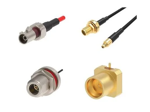
Examples of RF connectors, adapters, and cable interfaces used for converting different coaxial connection standards in RF systems.
Explain why RF connectors must preserve impedance continuity
The connector is physically short, but electrically it is not invisible. At RF frequencies, every transition in the signal path matters: cable conductor to center contact, dielectric to insulator, outer braid to connector body, connector body to mating interface, and then into the next port or cable.
Most RF communication and test systems use 50 ohm impedance. Video, CATV, and broadband systems commonly use 75 ohm impedance. Mixing them because “the connector fits” is a sourcing shortcut that can create reflection and measurement error. A 50 ohm BNC and a 75 ohm BNC may look similar to a buyer, but they should not be treated as the same RF part.
The same issue appears with adapters. An RF adapter can solve a temporary interface mismatch, but it also adds one more mating point. In low-risk setups, this may be acceptable. In higher-frequency testing or low-VSWR links, the adapter stack may become the hidden source of loss.
A better RF connector request should include at least these details: connector family, gender, impedance, mounting style, cable type, frequency range, and application. For a cable assembly, add cable length, connector count, and test requirement.
Show where RF connectors appear in antennas, modules, cables, and test equipment
RF connectors appear in different positions inside the same project. A wireless module may use a small SMA, MMCX, U.FL, or IPEX-style antenna connection. A test bench may use SMA, BNC, N Type, 3.5 mm, or 2.92 mm interfaces depending on frequency and measurement accuracy. Outdoor antenna systems often need stronger threaded connectors, larger cable compatibility, and better sealing.
Mounting style changes the requirement. A PCB connector must match the board layout. A bulkhead connector becomes the fixed RF port through a panel. A cable-end connector depends on cable OD, ferrule size, braid contact, and crimp or solder process. These details are easy to miss when the purchasing description only says “RF cable” or “SMA cable.”
For example, an SMA connector for RG316 should not be replaced with an SMA connector made for RG58 just because both are SMA. The rear body and ferrule may not fit the cable correctly. The assembly may pass a simple electrical test but fail pull force, shielding contact, or RF repeatability.
Clarify how connector mismatch creates reflection and signal loss
Mismatch is not always obvious. Sometimes the product works during a short bench test, then becomes unstable after installation. The cable is bent tighter, one adapter is added, or the connector is mated several more times. The RF margin disappears slowly.
Common causes include wrong impedance, poor center pin alignment, loose mating, damaged threads, weak braid contact, crushed dielectric, excessive solder heat, or a connector body not matched to the cable diameter. At low frequencies, the problem may be small. At several GHz, the same mechanical detail can affect return loss or insertion loss.
Continuity testing is still useful. It catches shorts, open circuits, and some assembly errors. It does not prove RF performance. For high-frequency RF cable assemblies, microwave adapters, or test leads, VSWR or insertion loss testing should be written into the purchasing requirement before production.
How Do You Choose Between SMA, BNC, N Type, TNC, and F Connectors?
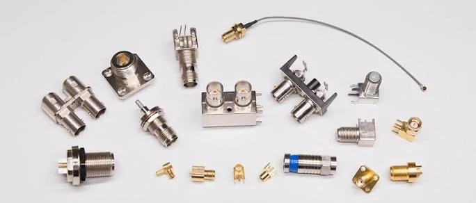
Overview of coaxial RF connectors and adapters including panel connectors, cable connectors, and conversion interfaces for RF applications.
Match compact RF devices with SMA connectors
SMA is widely used because it is compact, threaded, and available in many cable, PCB, panel, and adapter versions. It is common in antenna cables, RF modules, wireless equipment, test fixtures, and lab adapters.
The sourcing risk is assuming all SMA connectors are the same. A straight SMA male plug for RG58 or RG142 is not the same item as a right-angle SMA for RG316 or a bulkhead SMA female jack for a panel. Even when the front interface is correct, the rear body, pin, insulator, and ferrule must match the cable and termination method.
A clearer BOM note would be:
SMA male plug, 50 ohm, straight cable type, for RG58/RG142, gold-plated contact, PTFE insulator, crimp/solder termination, target frequency confirmed, visual and continuity inspection required.
That is much safer than writing only “SMA connector.”
Use BNC connectors for quick-lock test and video connections
BNC connectors are useful where fast connection is needed. The bayonet lock works well for many lab instruments, test leads, CCTV systems, and video applications. Technicians can connect and disconnect quickly without threading the interface each time.
The first check is impedance. BNC connectors are available in 50 ohm and 75 ohm versions. A 50 ohm RF test cable and a 75 ohm video cable should not be mixed casually. The second check is use condition. A bench cable moved every day needs good strain relief and stable mating. A fixed video installation may care more about cable preparation and compression quality.
Choose N Type connectors for stronger outdoor or antenna systems
N Type connectors are often selected when the interface needs more mechanical strength than a compact SMA. They are common in antenna systems, outdoor RF equipment, larger coaxial cables, and some higher-power paths.
Do not stop at the word “outdoor.” Confirm whether the connector is exposed to weather, mounted inside an enclosure, connected to a heavy cable, or frequently disconnected. Sealing, cable size, plating, thread quality, and installation stress can matter as much as the connector family name.
Compare TNC, F Type, PL259, and SO239 by use case
TNC is often useful where a threaded interface is preferred over a quick-lock BNC-style connection, especially where vibration or accidental disconnects are concerns. F Type is mainly used in 75 ohm TV, CATV, and broadband systems. PL259 and SO239 are common in legacy radio and UHF-style systems, but they should be checked carefully against frequency and impedance requirements.
| Connector Family | Common System | Key Advantage | Main Check |
| SMA | RF modules, test adapters | Compact threaded interface | Gender, frequency, cable fit |
| BNC | Lab test, CCTV, video | Fast bayonet connection | 50 ohm or 75 ohm |
| N Type | Antenna, outdoor RF | Rugged body | Sealing, power, cable size |
| TNC | Vibration-prone RF | Threaded BNC-style interface | Mating compatibility |
| F Type | TV, CATV, broadband | 75 ohm video systems | Cable type and compression style |
| PL259 / SO239 | Radio, UHF systems | Common legacy interface | Frequency and impedance limits |
| 2.92 mm / K | Microwave testing | Precision high-frequency interface | Connector care and mating quality |
This table is only a first filter. The final RF connector choice still needs gender, polarity, impedance, mounting style, cable compatibility, frequency range, and inspection requirements.
How Should Impedance Guide RF Connector Selection?
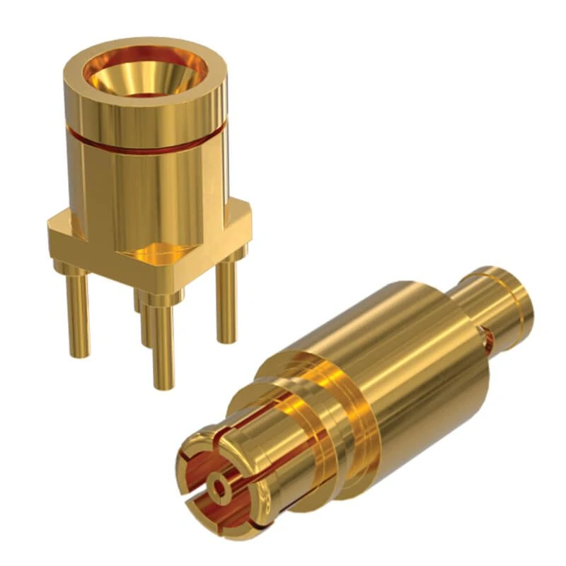
Illustration showing how RF connectors maintain signal integrity through proper impedance matching, connector structure design, and stable RF transmission paths.
Separate 50 ohm RF systems from 75 ohm video systems
Impedance is one of the first details to confirm because it quietly decides whether the connector belongs in the system at all.
Most RF communication, antenna, wireless module, and laboratory test systems use 50 ohm connectors and cables. Many video, CATV, broadband, and broadcast-style systems use 75 ohm parts. The two groups may share similar connector names, especially with BNC, but the electrical expectation is different. A connector that mates smoothly can still be the wrong impedance.
This is not only a theory problem. It becomes a purchasing problem when a buyer sends a photo and writes “BNC connector” without saying 50 ohm or 75 ohm. The supplier may provide a physically compatible part, but the RF path may no longer match the equipment, cable, or test setup. Once production starts, that kind of mistake is more expensive than checking the impedance at the RFQ stage.
Avoid mixing connector impedance only because the interface fits
A common sourcing trap is simple: the connector fits, so the order moves forward.
That may work for a temporary bench connection where the frequency is low and the signal margin is generous. It is less safe in a calibrated test path, antenna feed, RF module connection, or production cable assembly. Every impedance transition can increase reflection. The result may show up as worse return loss, unstable readings, reduced range, or inconsistent samples from batch to batch.
The risk is higher when adapters are added. A single adapter may be acceptable. Two or three adapters can turn a clean RF path into a chain of unknowns. Each interface adds mechanical tolerance, mating wear, plating condition, and possible impedance discontinuity. If the connector family changes from SMA to BNC, BNC to N Type, or SMA to F Type, the impedance and application should be checked again instead of assumed.
For long-term installation, a direct RF cable assembly is often cleaner than using multiple adapters. It reduces the number of mating points and gives the supplier a clear assembly target: connector A, connector B, cable model, length, impedance, and test requirement.
Match impedance across connector, cable, adapter, and equipment port
The connector should not be specified alone. It belongs to a chain.
A 50 ohm SMA connector on a 75 ohm cable is still a mixed path. A 75 ohm BNC adapter placed inside a 50 ohm RF test system is still a transition. A correctly labeled coaxial cable assembly can still fail if one end uses the wrong connector impedance or the adapter in the middle was not considered.
The easiest way to avoid this is to write the impedance into every RFQ line. Do not rely on product photos or past order names. For repeat orders, copy the confirmed specification instead of copying only the model number.
| System Need | Recommended Impedance | Common Connector Examples | Risk if Mismatched |
| RF communication | 50 ohm | SMA, N Type, TNC, many BNC | Reflection, lower signal margin |
| Lab testing | 50 ohm | SMA, BNC, N Type, 3.5 mm, 2.92 mm | Wrong calibration path or unstable reading |
| TV / CATV / video | 75 ohm | F Type, 75 ohm BNC | Visible signal quality loss or system mismatch |
| Mixed equipment | Confirm first | Adapter or custom cable assembly | Hidden impedance transition |
This table is a decision aid, not a substitute for the datasheet. If the system is sensitive, the final connector, cable, and adapter combination should be checked against the actual frequency band and inspection target.
How Does Frequency Range Narrow the Connector Choice?
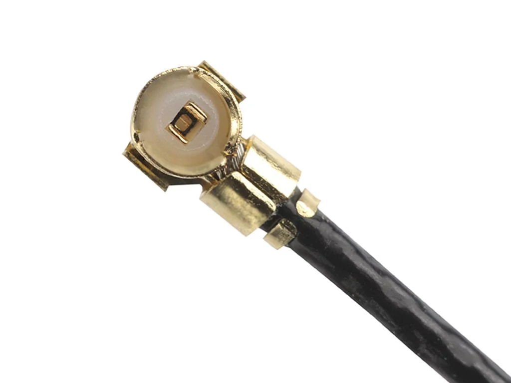
Example of an RF cable assembly showing connector termination and coaxial cable structure used in antenna, module, and laboratory RF applications.
Select connector families according to operating frequency
Frequency rating should be treated as a limit, not a decoration in the catalog.
A connector used at 400 MHz does not face the same conditions as a connector used at 6 GHz, 18 GHz, or 26.5 GHz. As frequency rises, interface geometry, dielectric consistency, center contact alignment, plating quality, torque, and mating condition become less forgiving. A connector that works well in a low-frequency control or video system may not belong in a microwave test setup.
The operating frequency should be lower than the connector’s rated range with enough margin for the application. If a system works at 5.8 GHz, a connector rated only slightly above that frequency may function, but it leaves less room for cable loss, adapter effects, production variation, and repeated mating wear. For test leads or low-VSWR work, more margin is safer.
Use microwave connectors when precision and repeatability matter
Microwave connectors are not only about reaching a higher GHz number. They are also about repeatable geometry.
In VNA testing, microwave modules, calibration paths, and precision adapters, the mating interface must stay consistent. Small damage to the center contact, worn threads, dirt on the interface, or poor alignment can change the measurement. That is why 2.92 mm, 3.5 mm, and other precision connector families require more careful handling than general-purpose low-frequency connectors.
SMA is widely used in GHz-range systems, but not every SMA part should be treated as a precision microwave connector. A low-cost SMA adapter may be acceptable for a simple antenna connection. It may be a poor choice for a repeatable test path near the upper frequency range. The same connector name does not guarantee the same RF behavior.
For production buyers, this creates a practical rule: specify the application, not only the interface. “SMA adapter” is vague. “50 ohm SMA male to SMA female adapter for RF test fixture, target 6 GHz, VSWR check required” is much clearer.
Check manufacturer ratings instead of assuming all connectors perform the same
Two connectors from the same family can have different ratings because the internal structure is different. Body design, dielectric material, center pin geometry, plating, machining tolerance, and assembly method all affect usable frequency.
Cable can also become the limit before the connector. A connector rated to a higher frequency does not make a lossy cable suitable for that frequency. If the cable assembly uses a small flexible coax, the cable attenuation and bend routing may matter more than the connector rating printed in the catalog.
The safer way is to filter the part by system band first, then confirm the actual assembly.
| Frequency Requirement | Connector Direction | Important Check |
| Low-frequency RF | BNC / TNC / N Type | Impedance and cable size |
| Compact GHz systems | SMA | VSWR, cable fit, mating quality |
| Outdoor antenna links | N Type / TNC | Sealing, power handling, cable support |
| Microwave testing | SMA / 3.5 mm / 2.92 mm | Precision, connector wear, torque control |
| Video / broadband | F Type / 75 ohm BNC | 75 ohm continuity |
A useful internal rule is to add a frequency margin note to the RFQ. For general RF connections, the connector rating should not sit right on top of the operating frequency. For test cables, repeatable measurements, or assemblies with adapters, ask the supplier whether the complete assembly can be checked at the target band.
How Do Mounting Styles Change RF Connector Selection?
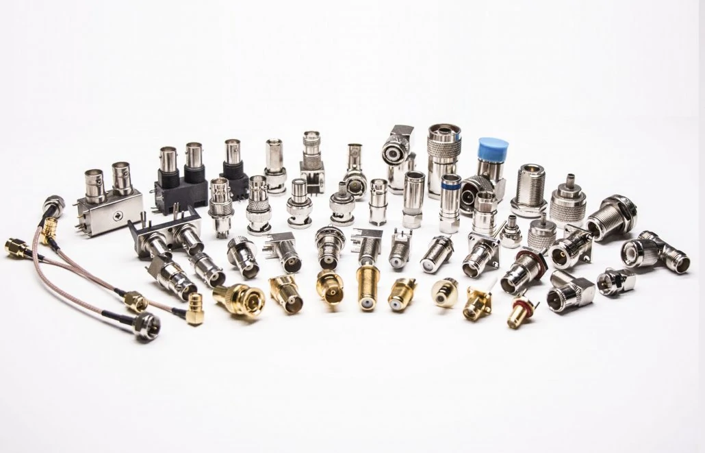
Collection of common RF connectors and adapters used in wireless communication, RF testing, antenna systems, and electronic equipment.
Choose cable-mount connectors for jumper cables and assemblies
The rear side of the connector is where many cable assembly mistakes begin.
The front interface may be correct. SMA mates with SMA. BNC locks into BNC. N Type threads on smoothly. But the cable side still has to fit the actual coax. RG316, RG58, RG142, RG174, RG6, low-loss coax, and semi-rigid cable do not use the same rear body or ferrule structure.
A connector made for a thin flexible cable may hold poorly on a larger cable. A connector made for a larger cable may leave the braid contact loose on a smaller cable. Either problem can pass a quick continuity check and still create trouble after bending, pulling, or RF testing.
For cable-mount connectors, confirm cable OD, dielectric size, braid contact, center pin fit, ferrule size, and termination method before production. Do not let the order description stop at “SMA cable” or “BNC cable.”
Use bulkhead connectors for through-panel RF ports
A bulkhead connector becomes part of the enclosure, not just part of the RF path.
That adds mechanical questions. Is the panel too thick for the thread length? Is there enough rear clearance for the cable bend? Does the nut seat flat? Is the washer in the right position? Will the cable be pulled after installation?
With SMA bulkhead connectors, the rear bend is often ignored. The panel looks clean from the outside, but inside the box the cable may be forced sharply downward or pressed against another component. That stress can move the center contact off-axis or weaken the termination over time.
Panel work should also control tightening. Too little torque may loosen the port. Too much torque can damage threads or distort the mounting area.
Match PCB, flange, bulkhead, and cable-end layouts to device structure
PCB connectors depend on footprint, soldering heat, board thickness, and mechanical support. Flange connectors depend on hole spacing, mating height, screw position, and flatness of the mounting surface. Cable-end connectors depend on routing and strain relief.
So the better question is not “which mounting style is best?” It is: where is the connector fixed, what is behind it, and what will happen after the cable is installed?
How Should RF Connectors Match Cable Assemblies and Adapters?
Decide whether to use an RF adapter or direct cable assembly
An adapter is useful when the job is temporary. Lab testing, prototype connection, equipment conversion, replacement checking — these are normal places for RF adapters.
Permanent assemblies deserve more caution.
Every adapter adds two mating interfaces. That means more thread wear, more possible contamination, more tolerance stack-up, and another small impedance transition. At low frequency, the difference may not matter much. Near the upper operating band, it can become the part nobody remembers to blame.
A direct cable assembly is cleaner when the path is known. Connector A, connector B, cable model, length, impedance, frequency range, and test target can all be built into one part number. Fewer joints. Fewer guesses.
Use a connector-to-cable checklist before production
Before production, the supplier should not need to guess the cable or interface details.
| Check Field | Required Detail |
| Connector Family | SMA / BNC / N Type / TNC / F Type / other |
| Connector Gender | Male / female |
| Impedance | 50 ohm / 75 ohm |
| Cable Type | RG316 / RG58 / RG6 / low-loss coax / semi-rigid |
| Mounting Style | Cable end / bulkhead / panel / PCB |
| Adapter Needed | Yes / no |
| Test Requirement | Continuity / VSWR / insertion loss |
| Drawing or Photo | Required for replacement |
This checklist is basic, but it prevents real production errors. A short line like “RF cable, 30 cm” is not enough for sourcing. It leaves too much room for the wrong gender, wrong cable size, wrong impedance, or wrong mounting style.
How Do Mechanical and Environmental Conditions Affect Connector Choice?
A connector on a test bench lives an easy life. A connector on an outdoor antenna does not.
For vibration, a threaded interface may be safer than a quick-lock style. For outdoor use, check sealing, plating, body material, cable jacket, and strain relief. For repeated mating, inspect thread wear and center contact condition. These small details decide whether the connector stays stable after months of handling.
Cable weight is another quiet issue. A heavy cable hanging from a small connector can loosen the interface. A tight bend behind a panel can pull the termination out of alignment. Waterproofing helps against moisture, but it cannot fix poor cable routing.
How Are RF Connectors Inspected Before Installation?
Start with the visible problems.
Bent center contact. Damaged thread. Cracked insulator. Loose body. Dirty interface. Wrong gender. Poor plating. These should be caught before the connector reaches a cable, panel, or test bench.
Continuity testing is still needed for cable assemblies. It confirms no open circuit and no short circuit. But it does not prove RF performance. A cable can pass continuity and still show poor VSWR at the working frequency.
For high-frequency assemblies, test leads, microwave adapters, or parts used in repeat measurement paths, add VSWR, return loss, or insertion loss checks to the order requirement.
| Inspection Item | Acceptance Requirement |
| Connector Family | Matches order |
| Gender | Confirmed |
| Impedance | 50 ohm / 75 ohm confirmed |
| Center Contact | Not bent, recessed, or loose |
| Thread / Bayonet | No visible damage |
| Insulator | No crack or deformation |
| Plating | Clean and complete |
| Cable Fit | Matches cable OD |
| RF Test | VSWR / insertion loss if required |
| Packaging | Protects contacts and threads |
Packaging is part of inspection too. A good connector should not arrive with the center pin exposed, threads rubbing against other parts, or cable assemblies packed without labels.
How Do You Specify RF Connectors for Purchasing or Replacement?
A useful RFQ removes interpretation.
Write the connector family, gender, impedance, mounting style, cable compatibility, frequency range, application, quantity, drawing or photo, and test requirement. For a replacement part, include front interface photos, rear termination photos, cable marking, thread detail, and panel mounting view.
A clearer RFQ line looks like this:
SMA female bulkhead connector, 50 ohm, panel mount, gold-plated contact, PTFE insulator, for internal RG316 cable connection, used on RF test enclosure, target frequency 0–6 GHz, visual and continuity inspection required.
For cable assemblies, add both ends, cable model, length, impedance, frequency range, routing condition, and inspection target.
FAQ
How do I choose the right RF connector for my device?
Start with the equipment port, impedance, frequency range, cable type, mounting style, and environment. Then select the connector family. Photos help, but they do not replace the electrical and mechanical details.
Is an RF connector the same as a coaxial connector?
They overlap in many RF systems. A coaxial connector keeps the center conductor, dielectric, and outer conductor in a controlled structure. RF connector is the broader sourcing term used for radio-frequency interfaces.
Why do some RF connectors use 50 ohm and others use 75 ohm?
50 ohm is common in RF communication, antenna, and test systems. 75 ohm is common in TV, CATV, video, and broadband systems. The connector, cable, adapter, and port should match.
When should I use an RF adapter instead of replacing the connector?
Use an adapter for temporary conversion, testing, or prototype work. For permanent installation or repeat production, a direct cable assembly usually gives fewer mating points and a cleaner BOM.
Can different RF connectors be used on one cable assembly?
Yes. One assembly can use SMA on one end and BNC, N Type, TNC, F Type, MMCX, U.FL, or another connector on the other end. The impedance and cable fit still need confirmation.
