
A BNC connection can pass a continuity test and still fail in the actual RF path.
This happens more often than many buyers expect. The connector locks correctly, the cable diameter looks acceptable, and the first bench test may show a working signal. However, once the assembly is installed into a measurement system, routed around equipment, or operated near the upper frequency limit, problems such as reflection, signal distortion, or unstable measurement results can appear.
The reason is usually not the bayonet locking mechanism itself. The issue is often hidden in the electrical details: impedance mismatch, unsuitable cable selection, incorrect connector type, or an assembly that was specified only by appearance.
For engineers and purchasing teams, a BNC connector should not be treated as a simple plug-and-play component. The correct selection depends on how the connector fits into the complete RF path: equipment port, cable type, operating frequency, impedance, and application environment.
How Does a BNC Connector Fit Into an RF Signal Chain?
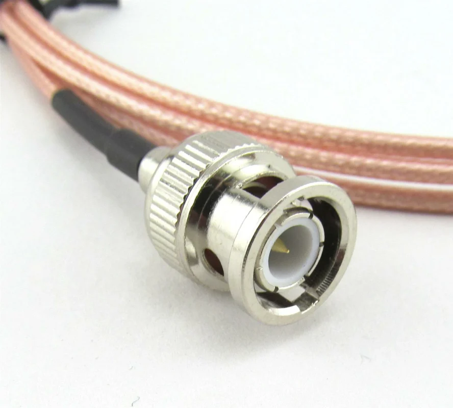
A BNC connector is often recognized because of its quick bayonet coupling design. Unlike threaded RF interfaces such as SMA or N Type connectors, BNC uses a push-and-twist locking structure, allowing fast connection and removal.
That mechanical convenience is the reason BNC remains common in many laboratory and industrial environments. It is frequently found on:
- Oscilloscopes
- Signal generators
- Frequency counters
- RF test instruments
- CCTV systems
- Broadcast video equipment
- Communication test setups
However, the connector interface is only one part of the system.
A BNC connector does not determine the entire RF performance by itself. The bayonet mechanism works, but the impedance transition can create unwanted reflections.
This is a common sourcing mistake: selecting a connector by interface shape while ignoring electrical compatibility.
Separate the Connector Interface From the Electrical Requirement
When purchasing a BNC connector, many specifications look similar:
- BNC male
- BNC female
- Cable connector
- Panel mount connector
- Bulkhead connector
- Adapter type
These describe the mechanical structure.
They do not answer the more important engineering questions:
- Is the system 50 ohm or 75 ohm?
- What frequency range is required?
- Which coaxial cable will be used?
- Is the connection for RF measurement or video transmission?
- How many mating cycles are expected?
- Is the connector installed indoors or in an outdoor enclosure?
A BNC connector that fits mechanically may still be unsuitable electrically.
Before selecting a connector, buyers should confirm four basic parameters:
| Requirement | Why It Matters |
| Impedance | Prevents mismatch and unnecessary reflection |
| Frequency range | Determines whether the connector structure is suitable |
| Cable type | Affects termination compatibility and RF loss |
| Application | Defines environmental and mechanical requirements |
A common example is replacing an existing cable assembly.
A customer may request:
“Need a BNC cable.”
This information is incomplete.
A better specification would be:
“50 ohm BNC male cable assembly using RG58 coaxial cable, 1 meter length, DC–3 GHz application.”
or:
“75 ohm BNC male cable assembly for SDI video transmission using RG59 cable.”
The second description gives the supplier enough information to avoid incorrect substitutions.
Identify Where BNC Connectors Are Still Used in Modern Systems
Although newer RF systems often use smaller or higher-frequency interfaces, BNC connectors continue to have practical value.
The reason is not that BNC is the highest-frequency connector option. It is because many instruments, test systems, and industrial installations were designed around this interface.
Communication and Industrial Equipment
Some communication systems continue to use BNC because of existing infrastructure and compatibility requirements.
For replacement projects, maintaining the original connector standard can reduce redesign costs.
The important point is that BNC usage depends heavily on system requirements. A connector selected for a laboratory measurement cable may not be the correct choice for a video installation.
How Can You Avoid Choosing a BNC Connector Only by Appearance?
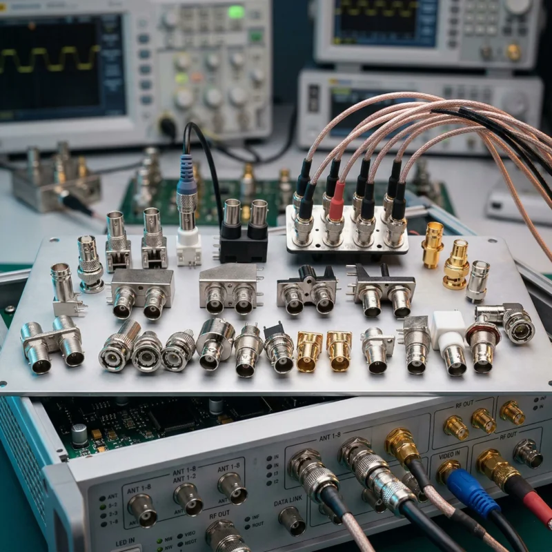
Two BNC connectors may look almost identical from the outside while serving different applications.
The external differences can be small:
- Body size
- Plating appearance
- Cable entry diameter
- Mounting style
But internal structures may differ:
- Contact geometry
- Dielectric design
- Center pin dimensions
- Impedance characteristics
- Frequency capability
For RF applications, the internal structure determines whether the connector performs correctly.
A practical purchasing rule:
Do not approve a BNC connector sample only because it mates successfully. Verify that the connector matches the electrical requirements of the system.
For production projects, the connector specification should include:
- Interface type
- Gender
- Impedance
- Cable model
- Cable length
- Operating frequency
- Termination method
- Inspection requirement
This prevents a common production problem: the sample works, but the production batch fails after cable length, routing, or assembly conditions change.
Practical Rule: Treat BNC as Part of the Assembly, Not a Separate Component
A BNC connector is only one element in an RF connection.
The final behavior depends on:
RF Assembly Result = Connector + Cable + Termination + Installation Condition
A good connector cannot compensate for:
- Incorrect cable impedance
- Excessive cable loss
- Poor crimping
- Damaged center contact
- Excessive bending stress
- Loose mechanical installation
For this reason, experienced RF buyers usually specify the complete cable assembly requirement instead of purchasing connectors separately without application information.
In the next section, we will compare 50 ohm BNC connectors and 75 ohm BNC connectors, explain why they are not interchangeable, and provide a practical impedance selection method for RF and video applications.
How Do You Choose Between 50 Ohm and 75 Ohm BNC Connectors?
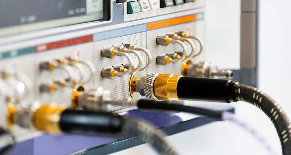
This image shows an RF test cable using a BNC connector adapter for interface conversion. Proper adapter selection helps maintain reliable connections between different RF devices and measurement equipment.
A BNC connector can look identical whether it is designed for 50 ohm or 75 ohm systems.
This is where many replacement projects encounter problems.
The connector body may connect correctly, the cable may be terminated successfully, and the system may even transmit a signal. However, if the impedance does not match the RF path, the connection can introduce reflection and reduce measurement accuracy.
The difference between 50 ohm and 75 ohm BNC connectors is not simply a product label. It represents two different transmission system requirements.
Use 75 Ohm BNC Connectors for Video and Broadcast Applications
75 ohm BNC connectors are mainly associated with video transmission systems.
Typical cables include:
| Cable Type | Application |
| RG59 | CCTV and general video transmission |
| RG6 | Longer distance video distribution |
| 75 ohm coaxial cable | Broadcast and SDI systems |
A common mistake is replacing a 75 ohm BNC cable assembly with a 50 ohm version because the connectors appear identical.
The system may still operate, but the electrical behavior changes.
For analog video, digital video, and high-speed serial signals, impedance consistency is especially important.
Why Can a Physically Compatible BNC Connection Still Be Electrically Wrong?
A connector mismatch does not always create an immediate failure.
This makes it difficult to identify without proper testing.
The connection may show:
- Signal present
- Normal DC continuity
- Correct mechanical locking
But the RF characteristics may be degraded.
Signal Distortion
In video and high-speed systems, mismatch can affect waveform quality.
The following comparison summarizes the difference:
| Parameter | 50 Ohm BNC | 75 Ohm BNC |
| Main Application | RF testing and communication | Video and broadcast |
| Common Equipment | Signal generator, spectrum analyzer | Camera, SDI equipment |
| Cable Family | RG58, RG142, RG316 | RG59, RG6 |
| System Goal | RF power transfer | Video signal transmission |
| Replacement Rule | Match existing 50Ω path | Match existing 75Ω path |
BNC Impedance Selection Decision Tree
Before ordering a BNC connector or cable assembly, use this quick selection process.
| Question | Decision |
| Is the equipment used for RF measurement? | Select 50Ω BNC |
| Is the system used for CCTV or video? | Select 75Ω BNC |
| Is the cable impedance already known? | Match connector impedance with cable |
| Is the system mixing different interfaces? | Evaluate adapter or conversion method |
| Does the frequency approach the connector limit? | Verify connector specification |
A simple selection rule:
BNC Impedance Selection = Equipment Impedance + Cable Impedance + Application Requirement
If any of these three factors are unknown, the connector should not be selected only by appearance.
How Can You Identify BNC Connector Gender Correctly?
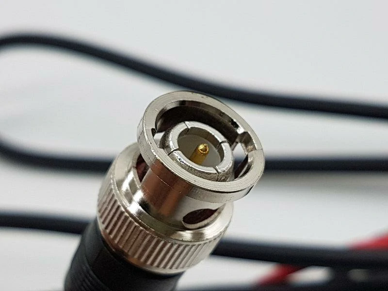
This image highlights the interface structure of a BNC connector, including the center contact and locking mechanism. Understanding connector construction helps avoid incorrect selection during RF system design.
Ordering the wrong BNC gender is one of the simplest mistakes to avoid, but it still happens frequently during sourcing.
Unlike some threaded RF connectors where the interface difference is obvious, BNC connectors rely on the center contact and coupling structure for identification.
Check the Center Contact and Coupling Structure Before Ordering
The basic identification method is:
BNC Male Connector
A BNC male connector normally has:
- Center pin contact
- External bayonet locking pins
- Plug structure
It connects into a BNC female interface.
Typical applications:
- Cable assemblies
- Test leads
- Equipment input cables
BNC Female Connector
A BNC female connector normally has:
- Center socket contact
- Bayonet receiving structure
- Jack interface
Typical applications:
- Panel-mounted connectors
- Instrument ports
- Equipment interfaces
The center contact is the first feature to check.
| Connector Type | Center Contact | Common Installation |
| BNC Male | Pin | Cable plug |
| BNC Female | Socket | Equipment port/panel mount |
Avoid Confusing Cable Ends, Panel Connectors, and Adapters
A BNC product request often becomes unclear because different product categories use similar descriptions.
For example:
“BNC connector” could refer to:
- Cable plug
- Panel mount jack
- Bulkhead connector
- PCB connector
- BNC adapter
These are not interchangeable.
A cable-mounted BNC connector requires compatibility with:
- Cable diameter
- Shield structure
- Termination method
A panel-mounted BNC connector requires compatibility with:
- Mounting hole size
- Panel thickness
- Fixing method
An adapter requires compatibility with:
- Interface A
- Interface B
- Impedance
- Frequency range
Confirm Mating Direction Before Building a Cable Assembly
For custom BNC cable assemblies, the complete connection path should be confirmed before production.
A basic specification should include:
| Item | Example |
| Connector A | BNC Male |
| Connector B | BNC Female |
| Cable Type | RG58 |
| Cable Length | 1 m |
| Impedance | 50Ω |
| Application | RF test |
This avoids a common production issue: the cable is manufactured correctly according to the drawing but cannot connect to the customer’s equipment because the mating direction was misunderstood.
Practical Note for Buyers
For standard BNC applications, gender selection is usually straightforward.
For custom cable assemblies, however, the supplier should receive the complete connection requirement rather than only the connector name.
A request like:
“Need 500 pcs BNC cable.”
does not define enough information.
A production-ready request should describe:
“500 pcs 50Ω BNC male-to-BNC female cable assemblies, RG58 coaxial cable, 1 meter length, for RF test equipment.”
The additional details reduce unnecessary sample revisions and production delays.
Which BNC Adapter Should You Choose for RF Conversion?
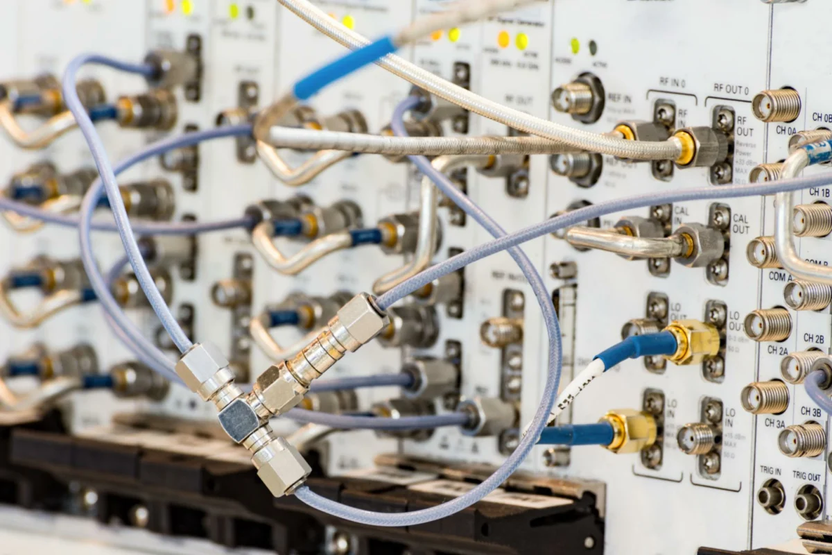
A BNC adapter is often used when existing equipment uses different connector standards.
In practical RF systems, connector conversion is common because instruments, cables, and modules are not always designed around the same interface.
Typical examples include:
- SMA to BNC adapter
- N Type to BNC adapter
- TNC to BNC adapter
- BNC to BNC gender adapter
However, an adapter should not be selected only by mechanical compatibility.
A correct BNC adapter requires matching:
- Interface type
- Gender
- Impedance
- Frequency range
- Application environment
A connector may physically mate while still creating an unsuitable RF transition.
Select BNC Adapters When Connector Conversion Is Required
Adapters are useful when replacing the entire cable assembly is unnecessary or too expensive.
For example:
A laboratory signal generator may have an SMA output, while the existing test cable uses BNC connectors.
Instead of replacing the complete cable system, an SMA-to-BNC adapter can provide the required interface transition.
Common adapter applications:
| Adapter Type | Typical Use |
| SMA to BNC | Connecting modern RF modules with BNC test equipment |
| N Type to BNC | Communication equipment and measurement systems |
| BNC to BNC | Extending or changing connector gender |
| TNC to BNC | Mixed RF equipment environments |
However, each adapter adds another mechanical interface into the signal path.
Reduce Unnecessary Adapters in High-Frequency Systems
In low-frequency applications, an additional adapter may have little visible impact.
At higher frequencies, the situation changes.
Each interface transition can influence:
- VSWR
- Return loss
- Insertion loss
A practical RF rule:
Use the minimum number of connector transitions required for the system.
If a permanent connection is required, a correctly specified cable assembly is often a better choice than stacking multiple adapters.
How Does Cable Selection Affect BNC Connector Performance?
A BNC connector does not operate independently.
The coaxial cable connected behind the interface directly affects the final RF behavior.
A common misunderstanding is:
“The connector frequency rating is high enough, so the assembly will work.”
This is incomplete.
The cable may become the limiting factor before the connector does.
Important cable parameters include:
- Impedance
- Attenuation
- Shielding
- Cable diameter
- Flexibility
- Bend radius
- Temperature rating
Match BNC Connectors With the Correct Coaxial Cable
The rear structure of a BNC connector must match the cable it terminates to.
For example:
A BNC connector designed for RG58 cable is not automatically suitable for RG316 cable.
The differences include:
- Cable outer diameter
- Dielectric thickness
- Shield structure
- Center conductor size
- Crimp dimensions
Common cable combinations:
| Cable | Typical Application | Selection Consideration |
| RG58 | General RF and test connections | Flexible and widely available |
| RG59 | 75Ω video systems | Common for CCTV applications |
| RG6 | Video distribution | Suitable for longer cable runs |
| RG316 | Compact RF assemblies | Small diameter and flexible |
The connector and cable should be treated as one assembly.
Consider Impedance, Frequency, and Shielding Together
A BNC cable assembly specification should consider several parameters at the same time.
Compare BNC and TNC Connectors When Vibration Resistance Matters
TNC uses a threaded coupling structure similar to N Type.
Compared with BNC:
- TNC provides stronger mechanical locking
- TNC is better suited for vibration environments
- BNC offers faster connection and removal
The correct choice depends on the system requirement rather than connector popularity.
How Should You Specify the Right BNC Connector for a Project?
A supplier cannot provide an accurate solution from only:
“Need BNC connectors.”
The specification should define the complete requirement.
BNC Connector Specification Checklist
| Parameter | Example |
| Connector Type | Male / Female |
| Mounting Style | Cable / Panel |
| Impedance | 50Ω / 75Ω |
| Frequency Range | DC–GHz |
| Cable Type | RG Series |
| Application | RF / Video / Test |
| Plating | Nickel / Gold |
| Quantity | pcs |
Create a Complete BNC Connector Requirement Statement
A complete request might look like:
50Ω BNC male connector for RG58 cable, DC–3 GHz RF testing application.
Or:
75Ω BNC female panel connector for RG6 video system installation.
This information allows suppliers to evaluate:
- Mechanical compatibility
- Cable termination
- Electrical performance
- Production requirements
Avoid Selecting BNC Connectors Only by Appearance
The final selection should consider three areas:
Electrical
- Impedance
- Frequency range
- VSWR
- Signal requirements
Mechanical
- Gender
- Mounting method
- Cable compatibility
- Mating cycles
Application
- RF testing
- Video transmission
- Industrial equipment
- Outdoor environment
A connector that looks correct may still be the wrong engineering choice.
FAQ
Is it safe to replace a 75 ohm BNC video cable with a 50 ohm BNC cable?
It is not a good replacement unless the system has been checked for that change. A 50 ohm BNC connector may physically mate with a 75 ohm video port, but the impedance is different. In CCTV, SDI, and broadcast systems, that mismatch can affect signal quality, especially over longer cable runs or higher-speed video signals. For video systems, keep the connector, cable, and equipment path consistently 75 ohm.
When is a BNC adapter acceptable, and when should I use a full cable assembly?
A BNC adapter is acceptable for short, temporary, or low-stress interface conversion, such as connecting a signal generator to an existing test cable. For permanent installation, tight routing, repeated movement, or higher-frequency testing, a properly specified BNC cable assembly is usually safer. Each adapter adds another interface, and every extra interface can add insertion loss, reflection, and mechanical stress.
Why can’t one BNC connector fit all coaxial cables?
The front BNC interface may look the same, but the rear termination area is built for a specific cable size and structure. RG58, RG59, RG6, and RG316 have different outer diameters, shield designs, dielectric sizes, and center conductor dimensions. If the connector body, ferrule, or center pin does not match the cable, the assembly may crimp poorly, loosen during use, or test badly at RF frequencies.
What details should I send before ordering custom BNC cable assemblies?
Send more than just “BNC cable.” A useful request should include connector A, connector B, male or female gender, 50 ohm or 75 ohm impedance, cable type, cable length, frequency range, application, and any inspection requirement such as VSWR or return loss. For example: “50Ω BNC male to BNC female cable assembly, RG58 coaxial cable, 1 m length, for RF test equipment.” That level of detail reduces wrong samples and production delays.
