
A semi rigid coax cable assembly can pass a basic continuity check and still fail when it enters the real RF environment.
A common situation happens during prototype development. The first cable sample is tested on an open bench with a straight routing path. The connector mates correctly, the signal looks acceptable, and the assembly is approved. During production, the cable needs to fit inside a metal enclosure with a fixed bend angle. The connector direction changes, the cable is formed differently, and the measured RF performance is no longer the same.
This is why semi rigid cable selection cannot be based only on connector type or cable diameter.
Engineers need to consider operating frequency, cable structure, bend radius, connector interface, installation space, and production repeatability before placing an order. A semi rigid assembly is usually selected for fixed RF paths where the cable shape must remain stable after forming.
How Should Semi Rigid Coax Cable Be Selected for Fixed RF Paths?
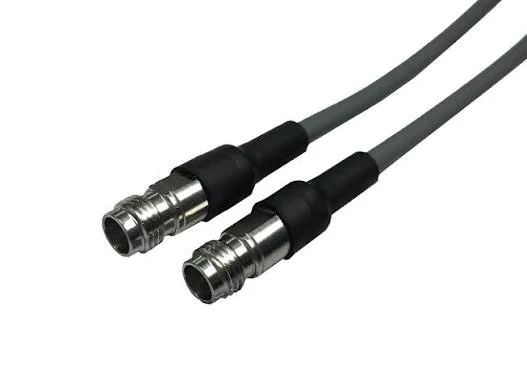
A semi rigid coax cable assembly uses a solid outer conductor structure to maintain a fixed routing shape after bending. It is commonly used in microwave test equipment, RF modules, radar systems, and communication devices where repeatable installation and stable electrical performance are required.
The first question before selecting a semi rigid cable is simple: will this cable move after installation?
If the answer is no, semi rigid coax may be a suitable choice. Its main advantage is not flexibility. It is stability after forming. Once the cable is bent into the required shape, it can maintain that route inside the equipment.
This makes it suitable for applications such as:
- microwave test fixtures
- radar modules
- RF measurement equipment
- communication equipment
- shielded electronic assemblies
A flexible RF cable is usually preferred when technicians need repeated movement, adjustment, or replacement. Semi rigid cable is different. It is designed for a planned path.
The mistake many buyers make is treating a semi rigid cable assembly like a standard jumper cable. A request such as “SMA to SMA cable, 100 mm” does not fully define the product. The supplier still needs to know the cable model, bend shape, connector orientation, and test requirements.
A better RF request should include:
| RFQ Item | Recommended Detail |
| Cable Type | Semi rigid coax cable |
| Cable Model | RG402 / RG405 / Custom |
| Impedance | 50 ohm |
| Length | Straight or formed length |
| Bend Requirement | Angle and radius |
| Connector Interface | SMA / N / 2.92 mm |
| Test Requirement | VSWR / insertion loss / continuity |
These details reduce production variation. Without them, two assemblies with the same cable length and connector type may still have different mechanical and RF behavior.
Match the Cable with the Operating Frequency Range
Frequency selection is another area where simple comparisons can create problems.
A cable with a smaller diameter is not automatically better for compact systems. A cable with a higher frequency rating is not automatically the correct choice. The complete RF path needs to be considered, including cable attenuation, connector capability, adapter transitions, and installation conditions.
For example, RG402 and RG405 are both commonly associated with semi rigid RF applications, but they are used differently.
Separate Fixed Assemblies from Flexible Jumper Cables
Semi rigid coax and flexible RF cable solve different engineering problems.
| Application | Suitable Cable Choice | Main Reason |
| Fixed microwave routing | Semi rigid coax | Stable formed shape |
| Test cable with movement | Flexible RF cable | Easier handling |
| Compact internal routing | Semi flexible coax | Better installation flexibility |
| Long cable distance | Low loss RF cable | Reduced attenuation |
Replacing a semi rigid assembly with a flexible cable may make installation easier, but it can also introduce new variables. The routing position may change, shielding behavior may change, and connector stress may increase.
For production equipment, repeatability is often more valuable than installation convenience.
How Can Bend Forming Affect Semi Rigid Cable Stability?
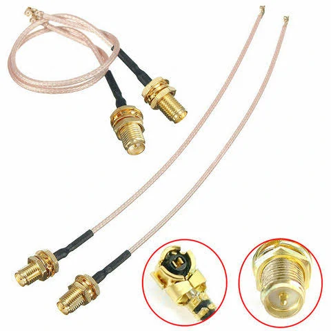
Semi rigid RF cable assemblies are widely used in fixed RF paths including microwave testing systems, radar modules, measurement equipment, and shielded electronic assemblies. Proper cable selection depends on mechanical layout and RF performance requirements.
The bend is part of the electrical design, not only a mechanical requirement.
Semi rigid cable uses a solid outer conductor structure that allows the cable to maintain its formed shape. However, incorrect bending can create problems. A bend that is too sharp may deform the cable structure. A bend placed too close to the connector can add stress to the termination area.
The cable may still pass continuity testing.
That does not confirm RF performance.
Define Bend Requirements Before Production
Before production begins, the cable drawing should define more than overall length.
Important details include:
- bend angle
- minimum bend radius
- connector direction
- cable orientation
- mounting position
- clearance requirements
A photo can show appearance, but a drawing provides repeatable production information.
For semi rigid assemblies used in microwave equipment or test fixtures, a simple drawing can prevent problems later during installation.
A practical bend record can include:
| Field | Requirement |
| Cable Model | RG402 / RG405 |
| Bend Angle | 45° / 90° / Custom |
| Bend Radius | Defined minimum value |
| Cable Length | End-to-end length |
| Connector Direction | Straight / Right angle |
| Drawing Available | Yes / No |
The earlier these details are confirmed, the easier it is to control assembly consistency and inspection results.
How Do RG402 and RG405 Support Semi Rigid RF Assemblies?
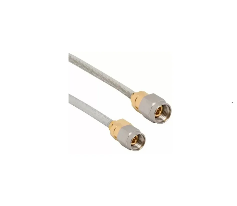
A cable choice that looks reasonable in a catalog can become difficult after it reaches the assembly stage.
RG402 and RG405 are often compared because both are used in semi rigid RF applications. However, the decision is rarely made by frequency number alone. In actual projects, engineers usually face a more practical question: can the cable fit the mechanical structure while keeping the RF path stable?
That is why RG402 and RG405 should be evaluated as part of the complete cable assembly.
Use RG402 Cable When Mechanical Stability Matters
RG402 is often selected for assemblies where the cable route is fixed and the available space allows a larger cable structure.
In laboratory equipment or microwave test fixtures, the cable position may need to remain unchanged over repeated measurements. A cable that shifts slightly after installation can introduce unwanted variation, especially when the system is operating near the upper frequency range.
RG402 is commonly considered for:
- microwave test systems
- fixed RF modules
- measurement fixtures
- equipment with defined cable routing
The larger construction can make the assembly more rigid, but it also means the design team needs to confirm bend requirements before production.
For example, a straight RG402 cable may fit easily during prototype testing. After the equipment housing is finalized, the required bend radius may leave limited clearance. This is why production drawings are usually more valuable than a simple cable length specification.
A practical RG402 assembly specification may include:
| Item | Example Requirement |
| Cable model | RG402 |
| Impedance | 50 ohm |
| Connector interface | SMA / N / 2.92 mm |
| Cable length | Defined after forming |
| Bend requirement | Drawing controlled |
| Test requirement | VSWR / insertion loss |
The connector selection also needs attention. A high-frequency connector attached to an unsuitable cable size does not automatically create a high-performance assembly. The cable diameter, termination method, and connector body must match.
Use RG405 When Space Is the Limiting Factor
RG405 is often considered when the RF path needs to fit into a smaller mechanical space.
Compact microwave modules, test adapters, and internal equipment layouts may leave very little room around the cable route. In these cases, a smaller semi rigid cable can make installation easier.
However, compact size also means the assembly usually has less room for adjustment.
A technician may be able to correct a small position error on a larger assembly. In a compact RG405 installation, a few millimeters of difference can affect whether the connector aligns correctly with the mounting point.
Compare RG402 and RG405 Before Releasing the BOM
The final decision should consider mechanical conditions as much as electrical requirements.
| Selection Point | RG402 | RG405 |
| Cable structure | Larger semi rigid coax | Smaller semi rigid coax |
| Installation space | Requires more room | Better for compact layouts |
| Mechanical support | Higher rigidity | Suitable for smaller assemblies |
| Typical usage | Fixed microwave paths | Compact RF modules |
| Main concern | Routing limitation | Forming accuracy |
There is no universal replacement between the two.
A design that works well with RG402 may not transfer directly to RG405 because the bend position, connector alignment, and installation method may change. The same applies in reverse. Selecting a smaller cable only to save space can create problems if the assembly requires stronger mechanical support.
How Should Engineers Compare Semi Rigid and Semi Flexible Coax?
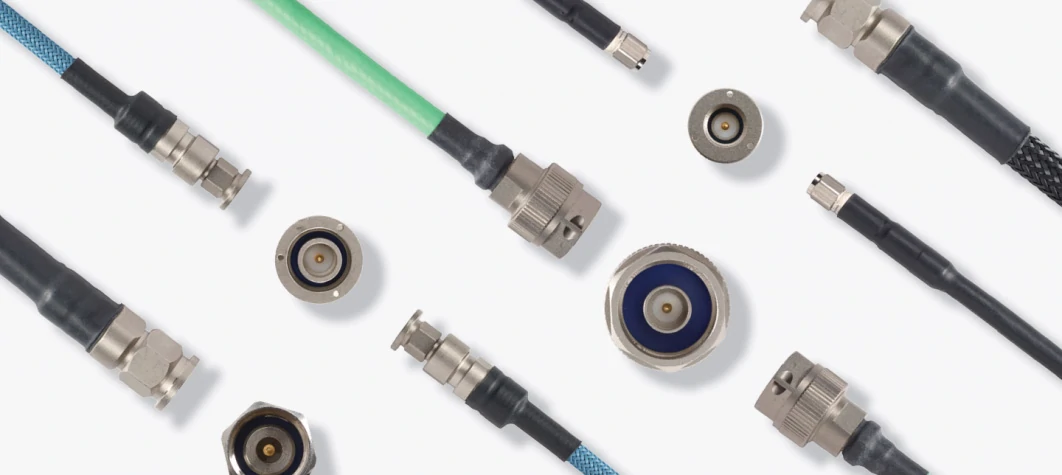
Miniature semi rigid coax cable assemblies help engineers connect RF modules where space is limited. Connector selection and cable forming accuracy are important factors affecting final assembly performance.
The difference between semi rigid and semi flexible coax becomes obvious after installation.
Semi rigid cable is normally formed into its final position. Semi flexible cable allows more movement during assembly. This difference affects not only installation but also production control.
For a prototype, flexibility may appear convenient. Engineers can move the cable slightly and find a workable position. During repeat manufacturing, that same flexibility can become a source of variation.
Different operators may route the cable differently. The connector may experience different stress. The final RF measurement may change from one assembly to another.
Check the Production Environment Before Changing Cable Type
A cable substitution should not be made only because one option is easier to install.
Before replacing semi rigid coax with semi flexible coax, engineers should review:
- required bend repeatability
- available installation space
- expected maintenance frequency
- RF test limits
- connector loading
- shielding requirements
A test fixture used every day may need a stable cable position more than easy adjustment. A serviceable device may have the opposite requirement.
This is where sourcing decisions become engineering decisions.
Semi Rigid vs Semi Flexible Selection Matrix
| Project Condition | Semi Rigid Coax | Semi Flexible Coax |
| Fixed microwave path | Suitable | Possible depending on design |
| Frequent movement | Limited | Better choice |
| Repeat production | Easier with drawing control | Requires routing control |
| Compact installation | Requires planning | More flexible |
| RF path consistency | Higher after forming | Depends on installation |
A supplier receiving a semi rigid cable request should ideally receive more than the connector names and length. The useful information is the complete application condition.
For example:
- operating frequency
- cable model preference
- connector interface
- final bend shape
- quantity
- inspection requirement
These details help prevent a common production issue: a cable assembly that works as a sample but becomes inconsistent during volume manufacturing.
Semi Rigid Cable Selection Decision Table
| Design Situation | Recommended Direction | Main Reason |
| Fixed microwave measurement path | Semi rigid coax | Stable formed route |
| Small internal RF module | RG405 option | Better space utilization |
| Larger enclosure with fixed routing | RG402 option | Stronger mechanical structure |
| Frequent adjustment required | Semi flexible or flexible cable | Easier handling |
| Repeat production order | Drawing-controlled assembly | Better consistency |
The cable model is only one part of the decision. The final assembly depends on how the cable, connectors, forming process, and inspection method work together.
How Do Connectors and Terminations Control Microwave Cable Stability?
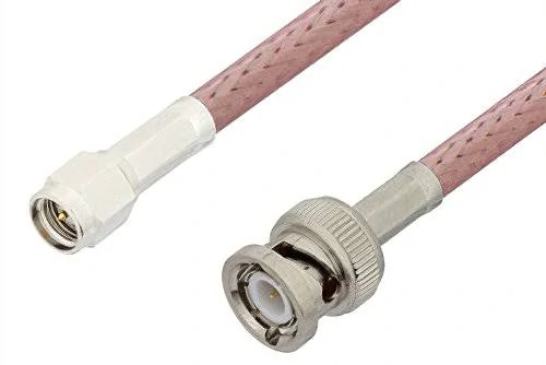
BNC semi rigid coax cable assemblies provide convenient RF connections for measurement instruments and communication equipment. The cable design helps maintain shielding and signal stability in fixed installation environments.
A semi rigid cable assembly is only as stable as its weakest connection point.
Many RF problems are not caused by the cable itself. The cable model may be correct, but the connector interface, termination method, or assembly process can introduce unexpected variation.
This is especially noticeable at microwave frequencies. A connector that looks identical from the outside may have different internal dimensions, contact structures, or cable compatibility. When the assembly operates near the upper frequency limit, small differences can affect VSWR, return loss, and insertion loss.
Before ordering a semi rigid coax cable assembly, confirm:
- connector interface
- gender
- impedance
- frequency requirement
- cable compatibility
- termination method
- test requirement
Match Connector Frequency Rating With Cable Capability
The connector frequency rating should not be viewed separately from the cable assembly.
A connector rated for a high frequency range does not automatically improve the complete assembly. The final result depends on the cable type, connector design, termination quality, and assembly process.
For example, an SMA connector may be suitable for many RF applications, but the rear cable entry and termination method must match the semi rigid cable size. A poor mechanical match can create stress at the connection point.
Common connector options for semi rigid assemblies include:
| Connector | Typical Application |
| SMA | General RF and microwave assemblies |
| N Type | Higher power or outdoor RF systems |
| 2.92 mm | Higher-frequency precision test applications |
The connector should be selected together with the cable model.
A connector designed for a smaller cable cannot simply replace one designed for a larger cable because the mechanical structure, contact alignment, and termination process may be different.
Prevent Connector Stress After Cable Forming
A formed cable should install naturally.
If the installer needs to force the connector into position, the cable shape may not match the equipment requirement. This can create long-term stress on the connector interface.
Semi Rigid Cable Assembly Loss Formula
The calculation should consider:
| Field | Description |
| Frequency | Target operating frequency |
| Cable Model | RG402 / RG405 / Custom |
| Cable Length | Actual formed length |
| Connector Count | Number of interfaces |
| Adapter Count | Number of transitions |
| Test Requirement | Insertion loss / VSWR |
This helps identify whether the cable is actually the main source of loss.
In some assemblies, changing the cable model provides limited improvement because the main loss comes from unnecessary adapters or connector transitions.
What Information Should Be Included in a Semi Rigid Cable RFQ?
Incomplete RF requests create unnecessary communication between suppliers and engineers.
A request containing only:
“SMA cable, 200 mm”
does not define a production-ready assembly.
A better RFQ should describe the complete cable path.
Recommended information:
| RFQ Field | Example |
| Cable Type | Semi rigid coax cable |
| Cable Model | RG402 / RG405 |
| Impedance | 50 ohm |
| Length | 100 mm / 300 mm / Custom |
| Bend Shape | Straight / 90° / Drawing |
| Connector A | SMA male |
| Connector B | SMA female / N / 2.92 mm |
| Frequency Range | DC–6 GHz / DC–18 GHz |
| Test Requirement | VSWR / insertion loss |
How Should Semi Rigid Cable Assemblies Be Tested Before Shipment?
Visual inspection is useful, but it cannot confirm complete RF performance.
A cable may look correct while still having problems that only appear during electrical testing.
Typical inspection items include:
- cable model confirmation
- connector interface check
- cable length measurement
- bend shape inspection
- continuity test
- VSWR measurement
- insertion loss test
| Inspection Item | Check Requirement |
| Cable Model | Correct specification |
| Connector A/B | Correct interface |
| Impedance | 50 ohm |
| Length | Within tolerance |
| Bend Shape | Matches drawing |
| RF Test | According to requirement |
| Packaging | Protect formed shape |
Packaging is often overlooked.
A semi rigid cable that is correctly formed during production can be damaged if it is compressed or bent during transportation. For custom assemblies, packaging should protect the final cable shape until installation.
FAQ
When should I choose semi rigid coax instead of flexible RF cable?
Choose semi rigid coax when the RF path needs a fixed shape and repeatable installation position.
Can semi rigid coax cable be bent after production?
Production assemblies should normally follow the approved drawing.
What tests should be requested for semi rigid cable assemblies?
Typical tests include continuity, insertion loss, VSWR, and return loss depending on the application requirements.
What should I prepare before asking for a semi rigid coax cable quotation?
A supplier normally needs more than “SMA cable” or “200 mm cable”.
The useful information is the cable model, connector A/B, cable length, bend drawing or sample, operating frequency, and required test items. If the cable needs to fit into an enclosure, a drawing or marked photo can save several rounds of adjustment.
Why is my semi rigid cable assembly showing unstable VSWR after bending?
The cable itself may not be the only factor. A tight bend, incorrect forming position, or stress near the connector area can affect the RF path. This is why semi rigid assemblies are usually produced according to a defined drawing instead of being adjusted freely during installation.
Final Buying Guidance
A semi rigid cable assembly should be treated as a complete RF component, not just a cable with two connectors.
The cable model, forming process, connector selection, and testing method all influence the final result.
Before ordering, confirm:
- operating frequency
- cable model
- impedance
- cable length
- bend drawing
- connector interfaces
- RF test requirements
For applications near the upper frequency range, providing these details early can prevent redesign work later.
A well-defined RF request helps engineers receive an assembly that fits the equipment, matches the expected electrical behavior, and remains consistent during production.
