
A cable assembly can look correct on the drawing and still create problems after it enters production.
This happens frequently in RF projects. The connector interface matches the equipment, the cable length is correct, and the first sample passes basic electrical checks. The issue appears when the assembly is installed into the final enclosure, routed around other components, or measured at a higher frequency range.
The reason is simple: an RF cable is not only a wire between two points.
The cable diameter, dielectric structure, shielding method, connector transition, and forming process all influence the final RF path.
But selecting RG405 is not just about choosing a smaller coax cable.
A shorter cable does not automatically mean lower loss. A higher-frequency connector does not automatically improve the complete assembly. A cable that works in a laboratory setup may behave differently after bending, mounting, and repeated production handling.
This guide focuses on the practical questions behind RG405 selection:
- Where does RG405 fit compared with other semi-rigid coax cables?
- When does the smaller structure become an advantage?
- How should engineers match RG405 with SMA connectors and RF assemblies?
- What should buyers include in a cable specification before requesting a quotation?
Why Is RG405 Cable Selected for High Frequency RF Systems?
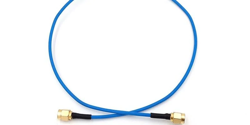
A flexible-length RG405 SMA cable jumper designed for RF equipment connections. The semi rigid coax structure helps maintain consistent impedance and signal integrity in fixed installations.
A common mistake during RF sourcing is starting with the connector.
Many purchase requests begin with a connector name such as SMA, N-type, or 2.92 mm, while the cable specification is left unclear. In practice, the connector only represents one part of the RF path. The cable behind it determines how the signal is carried through the system.
An rg405 cable belongs to the semi-rigid coaxial cable family. Compared with flexible RF cables, it is intended for installations where the cable position should remain stable after forming.
That difference matters in equipment where repeatability is more valuable than flexibility.
A semi rigid coax cable is usually selected for applications such as:
| Application | Reason Engineers Consider RG405 |
| Microwave test equipment | Fixed routing helps maintain repeatable measurements |
| RF modules | Smaller diameter helps fit limited internal space |
| Communication equipment | Stable impedance path inside the assembly |
| Laboratory fixtures | Reduces variation caused by cable movement |
| Short antenna connections | Provides controlled RF transmission path |
In a laboratory environment, cable movement can sometimes introduce measurement differences that are difficult to trace. A flexible cable may be convenient during setup, but repeated repositioning can change the physical condition of the RF path.
RG405 avoids part of this problem because the cable keeps its formed shape.
This does not mean semi-rigid cable is always the correct choice.
If an application requires frequent bending, maintenance access, or portable operation, a flexible coax solution may be more suitable. RG405 is mainly valuable when the installation position is defined and repeatability matters.
How Does RG405 Cable Structure Support Stable RF Transmission?
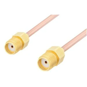
An RG405 semi rigid coaxial cable assembly using SMA connectors. The combination of RG405 cable and SMA interface provides a compact RF connection solution for applications requiring controlled impedance and repeatable performance.
The internal construction of a coaxial cable determines much more than its appearance.
A typical RG405 cable structure contains four basic sections:
| Cable Layer | Function in RF Assembly |
| Center conductor | Carries the RF signal |
| Dielectric material | Maintains conductor spacing and impedance |
| Outer conductor / shield | Provides shielding and return path |
| Outer jacket or protection layer | Supports mechanical handling |
The distance between the center conductor and outer conductor is especially important.
For a 50Ω RF system, this geometry needs to remain controlled. Changes caused by poor termination, incorrect connector matching, or mechanical damage can affect VSWR and return loss.
This is one reason why RF cable assembly suppliers usually treat cable and connector selection together.
A frequent production issue is using a connector that physically fits but does not match the cable construction.
For example:
- The connector body may accept the cable diameter.
- The assembly may pass continuity testing.
- The appearance may look normal.
However, problems can still exist at the RF transition area:
- center pin alignment is inconsistent;
- shielding contact is incomplete;
- soldering changes the dielectric area;
- mechanical stress affects the connection point.
At lower frequencies, these issues may remain unnoticed. As frequency increases, small mechanical differences become more visible during VNA testing.
When Do Standard Flexible RF Cables Become a Less Suitable Choice?
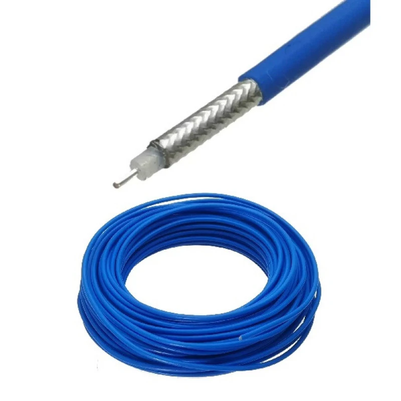
The internal structure of RG405 coaxial cable shows the conductor, dielectric material, braided or metal shielding layer, and protective outer layer. Each part affects impedance control, shielding effectiveness, and RF performance.
Not every RF system needs a semi-rigid cable.
Flexible coax cables remain widely used because they are easier to install and can handle movement. The selection depends on the actual working environment.
RG405 becomes a candidate when the project has several of these conditions:
- limited installation space;
- fixed cable routing;
- microwave frequency operation;
- repeated measurement requirements;
- controlled phase or impedance requirements.
A practical example is an RF test fixture.
During prototype testing, engineers may connect equipment with a flexible jumper because it is convenient. Later, when the fixture becomes a production test platform, cable movement and inconsistent routing can affect repeatability.
At that stage, a formed semi-rigid assembly may provide a more stable solution.
However, buyers should also consider the complete RF path.
The final loss is not determined only by the cable.
An assembly using RG405 cable with multiple adapters may perform differently from a direct cable connection.
This is why RF suppliers usually need several details before recommending a cable assembly:
| Required Information | Example |
| Cable type | RG405 |
| Impedance | 50Ω |
| Frequency range | Operating GHz range |
| Length | Custom length |
| Connector | SMA male / SMA female |
| Test requirement | VSWR / insertion loss |
RG405 Application Decision Table
Before selecting RG405 cable, engineers can use the following quick evaluation:
| Project Requirement | RG405 Suitability | Additional Check |
| Compact internal RF routing | Suitable | Confirm bend shape and space |
| Fixed microwave connection | Suitable | Verify frequency range |
| Portable equipment cable | Depends | Consider flexibility requirement |
| High-frequency test jumper | Suitable | Check connector and loss |
| Long-distance RF transmission | Depends | Calculate attenuation |
A useful specification rule:
The correct RF cable is the one that matches the system conditions, not simply the cable with the highest frequency number.
For procurement teams, providing cable type, connector interface, operating frequency, length, and test requirement at the quotation stage can prevent incorrect substitutions later.
How Does RG405 Cable Structure Affect Real RF Assembly Performance?
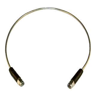
RG405 semi rigid coaxial cable is suitable for RF modules, microwave equipment, and test systems that require stable cable positioning and consistent electrical characteristics.
A cable drawing can look simple: one cable, two connectors, one specified length.
But during production, RF cable assemblies rarely fail because someone forgot the cable name. More often, problems come from details around the cable structure.
A semi-rigid cable has very little tolerance for incorrect handling. The cable is expected to keep a defined shape after forming, which is exactly why engineers choose it. The same characteristic also means that installation methods, bending operations, and connector termination become part of the final RF performance.
For an RG405 cable, the outer conductor is not just a protective layer. It is part of the RF transmission structure.
The relationship between the inner conductor and outer conductor creates the impedance environment. When that relationship changes, the effect may appear as increased reflection, unstable VSWR, or unexpected insertion loss.
This is why a continuity test alone is not enough for high-frequency cable assemblies.
A cable can pass:
- conductor connection check;
- short/open circuit inspection;
- visual appearance inspection;
and still show problems during VNA measurement.
The missing factor is that continuity only confirms the electrical path exists. It does not confirm that the RF path behaves correctly at the target frequency.
For RG405 assemblies, suppliers and engineers usually pay attention to several construction points:
| Area | What Needs Attention |
| Cable forming | Avoid excessive deformation during bending |
| Connector transition | Maintain proper center pin alignment |
| Shield connection | Ensure stable grounding path |
| Soldering process | Avoid affecting dielectric area |
| Final inspection | Verify electrical performance when required |
A small mechanical difference that seems insignificant at low frequency can become visible when the assembly moves into the microwave range.
Why Do Engineers Use Semi Rigid Coax Cable in Fixed RF Paths?
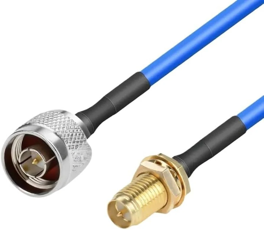
A customized RG405 RF cable assembly with SMA and N type connectors. Connector selection, cable routing, and termination quality directly influence final RF performance.
There is a reason semi-rigid cable appears frequently inside test equipment and RF modules.
The cable is not expected to move after installation.
A flexible cable is useful when an operator needs to connect and disconnect equipment repeatedly. A semi-rigid cable is used when the RF path itself needs to stay consistent.
Consider a production test fixture.
During development, engineers may use a standard flexible jumper because it is convenient. After the design moves into production, hundreds or thousands of units need to be tested with the same fixture.
At that stage, repeatability becomes more important.
If the cable position changes from one test to another, several variables can appear:
- different cable routing distance;
- different bending angle;
- different stress near the connector;
- different spacing from nearby metal parts.
These changes may not damage the cable, but they can influence measurement consistency.
RG405 helps by keeping the formed route stable.
However, this does not mean the cable should be bent repeatedly during installation.
A common mistake is treating semi-rigid cable like flexible coax. During early assembly, technicians may adjust the cable several times to achieve a better mechanical fit.
How Should Engineers Compare RG405 Cable With RG402 Cable?
RG405 and RG402 are often compared because both are used in semi-rigid RF applications.
The choice is usually not based on a simple “better or worse” decision.
The real question is:
Which cable creates fewer problems for this specific assembly?
RG402 has a larger physical structure. That can provide advantages when mechanical strength and lower attenuation are priorities.
RG405 has a smaller diameter, which can be useful when the enclosure becomes the limiting factor.
A practical comparison:
| Selection Factor | RG405 | RG402 |
| Installation space | Better for compact assemblies | Requires more space |
| Cable routing | Easier in crowded layouts | More suitable for open routing |
| Mechanical rigidity | Suitable for fixed paths | Higher mechanical margin |
| Compact RF modules | Common consideration | May be oversized |
| Larger microwave assemblies | Depends on design | Often considered |
For example, a communication module may have several RF channels placed close together. In that situation, saving a few millimeters of cable diameter can simplify the entire mechanical design.
But for a larger microwave test system mounted on a fixed frame, the extra mechanical support of a larger cable may become more valuable.
The wrong approach is replacing one with another only because both are labeled as 50Ω semi-rigid coax.
Before making a substitution, check:
- operating frequency;
- required loss budget;
- available installation space;
- connector compatibility;
- environmental conditions.
What Happens When RG405 Is Used Outside Its Intended Application?
Most cable selection mistakes happen because a cable works during the first evaluation.
The prototype passes.
The customer approves the sample.
The problem appears months later when production volume increases.
A typical example:
A short RG405 cable assembly performs well during laboratory testing. Later, the same design is installed in a different enclosure where the cable route becomes tighter. The connector position changes slightly, the cable is forced into a different shape, and the production result is no longer identical.
The cable model did not change.
The application condition changed.
This is why RF cable specifications should include more than just the cable number.
A useful RF requirement should mention:
| Specification Item | Example |
| Cable model | RG405 |
| Impedance | 50Ω |
| Length | 150 mm |
| Connector A | SMA Male |
| Connector B | SMA Female |
| Operating frequency | Target GHz range |
| Test requirement | VSWR / insertion loss |
This information gives the supplier enough context to select the correct assembly method.
How Should RG405 Cable Loss Be Evaluated Before Production?
Cable loss is another area where assumptions often create problems.
A shorter cable normally reduces attenuation, but the cable itself is only one part of the signal path.
The complete RF route includes:
- coaxial cable;
- connector interface;
- adapter transition;
- assembly quality.
This calculation becomes useful during design review.
For example, if a system operates close to its allowable loss limit, adding another adapter or changing the connector type may consume the remaining margin.
The cable itself may not be the problem.
The complete path needs to be considered.
RG405 Cable Selection and Loss Review Sheet
Before releasing an RF cable assembly drawing, engineers can review the following points:
| Check Item | Confirm |
| Cable model | RG405 |
| Impedance | 50Ω |
| Operating frequency | Within required range |
| Cable length | Final installed length |
| Connector type | Correct interface and gender |
| Adapter quantity | Minimize unnecessary transitions |
| Loss requirement | Defined before production |
| Test method | VNA / VSWR / insertion loss |
This type of specification prevents a common purchasing issue: receiving a cable assembly that physically matches the drawing but does not meet the actual RF requirement.
SMA Termination Is Often the First Place to Check in an RG405 Assembly
During RF cable assembly evaluation, the cable itself is usually not the first thing that causes trouble.
The problem often appears where two parts meet.
An RG405 cable with the correct length and impedance can still show different measurement results if the connector termination is not matched correctly.
This happens because the SMA connector is not only an interface for mechanical connection. The rear section of the connector becomes part of the RF transmission path.
The center conductor position, dielectric support, and shielding connection all affect the transition area.
A common mistake in sourcing is comparing connectors only by the front interface.
Two SMA connectors may look identical from the outside, but one may be designed for RG405 semi rigid coax cable while another is intended for a different cable diameter.
They may both screw onto the same equipment.
They may both pass a continuity test.
The difference appears when the assembly is checked with RF measurement equipment.
What Details Should Be Confirmed Before Ordering RG405 Cable Assemblies?
A short RF inquiry can create long discussions if the specification is incomplete.
For example, a request saying:
“RG405 cable, SMA connector, 500 pcs”
still leaves several production questions.
The supplier may not know:
- straight connector or right-angle connector;
- fixed length or tolerance range;
- formed shape requirement;
- operating frequency;
- electrical test requirement.
For sample development, these details can be confirmed gradually.
For production orders, they should be defined before assembly begins.
A practical specification normally includes:
| Item | Example |
| Cable model | RG405 |
| Impedance | 50Ω |
| Cable length | 100 mm |
| Connector | SMA male / SMA female |
| Cable shape | According to drawing |
| Application | RF module / test fixture |
| Inspection | VSWR or insertion loss if required |
This type of information is also useful when comparing suppliers.
Two quotations may look similar because both mention RG405 and SMA. The difference may be hidden in:
- connector quality;
- assembly method;
- testing process;
- production consistency.
Production Experience: Why One Sample Does Not Always Represent the Whole Batch
RF cable assemblies are often easy to approve at the sample stage.
A technician can spend more time checking one piece. The cable can be positioned carefully. The connector can be adjusted manually.
Mass production is different.
The same design may involve:
- multiple operators;
- repeated forming operations;
- different production batches.
Small differences may appear if the process is not controlled.
For RG405 assemblies, production attention is usually placed on several areas.
Cable forming
Semi-rigid cable keeps its formed shape.
That is one of its advantages.
It also means the forming process needs consistency. If the bend position changes from one assembly to another, the mechanical installation and RF path may not remain identical.
Connector installation
The connector attachment process affects both mechanical strength and electrical behavior.
Issues that may appear include:
- uneven soldering;
- poor shield connection;
- incorrect center conductor position.
These problems are not always visible from the outside.
Batch inspection
A production record is useful when the same cable assembly is purchased repeatedly.
Instead of checking only the finished product, engineers can trace:
- cable model;
- connector model;
- production date;
- inspection result.
Which Tests Are Useful for RG405 Cable Assemblies?
The required test method depends on where the assembly will be installed.
A cable inside a low-frequency control system and a cable used for microwave measurement equipment do not have the same acceptance requirements.
Typical checks include:
| Test | Purpose |
| Continuity | Confirms electrical connection |
| Dimension inspection | Confirms mechanical requirements |
| VSWR | Checks impedance matching |
| Return loss | Measures reflected signal |
| Insertion loss | Measures transmission loss |
One thing worth mentioning is that continuity testing is often misunderstood.
A cable can pass continuity and still have RF problems.
Continuity only verifies that the conductor path is connected. It does not show whether the assembly performs correctly at the operating frequency.
For higher-frequency RG405 cable assemblies, RF measurement becomes more meaningful than a simple electrical check.
RG405 Cable Assembly Inspection Reference
Before releasing a production batch, an engineering team may record the following information:
| Check Item | Record |
| Cable type | RG405 |
| Connector type | SMA / other |
| Cable length | Actual value |
| Assembly shape | Approved drawing |
| Appearance | Inspection result |
| Continuity | Pass / Fail |
| VSWR | Measured value |
| Insertion loss | Measured value |
The purpose is not to create unnecessary inspection steps.
The purpose is to make future production repeatable.
When a customer orders the same RG405 cable assembly several months later, the previous records provide a reference point.
FAQ
Can RG405 cable be assembled with SMA connectors?
Yes. RG405 is frequently used with SMA connectors in compact RF assemblies.
Can RG405 cable be used with SMA connectors?
Yes, RG405 cable is commonly assembled with SMA connectors in RF modules, test fixtures, and microwave applications.
The important point is not only the SMA interface itself. The connector rear section needs to match the RG405 cable structure, including cable diameter, center conductor position, and termination method.
What details should be included when ordering a custom RG405 cable assembly?
A cable model alone is usually not enough for production.
The supplier normally needs the cable length, connector combination, impedance, operating frequency, cable routing shape, and any required test standard.
For example, an RG405 assembly with SMA connectors may need different processing depending on whether it is installed in a compact module, laboratory equipment, or a production test fixture.
Providing these details early helps avoid changes after samples are produced.
Can I select an RG405 cable assembly only by checking the connector type?
The connector interface is only part of the selection.
For an RG405 assembly, the cable size, impedance, working frequency, cable length, and installation method also need to be confirmed.
Two assemblies with the same SMA connector may not have the same RF characteristics.