
A cable can pass continuity and still be wrong for the RF path.
That is a common problem with SMA cable assembly sourcing. The part looks simple in a photo. Both ends may screw on smoothly. A multimeter shows no open circuit and no short. Then the cable is installed inside a wireless device, test fixture, GPS receiver, antenna box, or RF module, and the measured result is not what the engineer expected.
The failure may not come from a broken cable. It may come from the wrong coax type, a poor bend near the connector, a standard SMA and RP-SMA mix-up, or a connector body that was never made for that cable diameter. At higher frequencies, these details do not stay hidden for long.
An SMA cable assembly should be treated as a finished RF signal path. Connector interface, cable family, length, shielding, termination method, bend space, and inspection requirement all need to work together.
How Should an SMA Cable Assembly Be Specified for a Real RF Link?
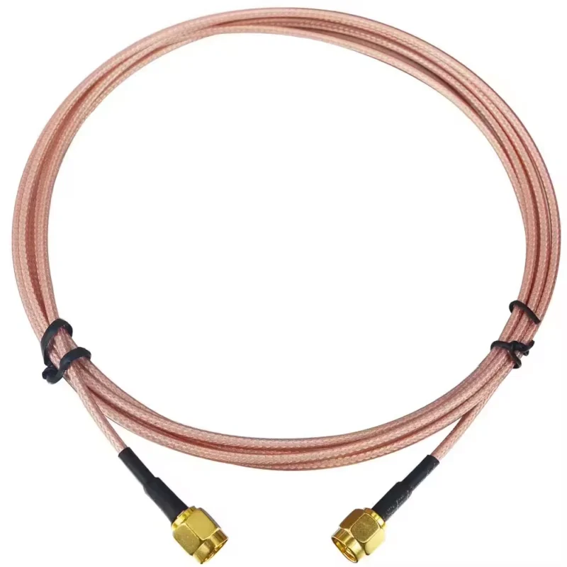
Start with the link, not the cable name.
A weak request says: “Need SMA cable, 300 mm.”
A useful request says: “SMA male straight to SMA female bulkhead, RG316, 300 mm, 50 ohm, used from enclosure wall to RF board, continuity test required, VSWR check at 2.4 GHz if available.”
The second version gives production something real to build. It also gives purchasing a record that can be repeated later.
An SMA cable assembly is not defined by the front interface alone. The rear cable matters just as much. A connector made for RG316 should not be substituted with a connector made for RG58 only because both are called SMA. The ferrule, rear body, center pin, dielectric support, and crimp area are different. A mismatch may still look assembled, but the braid contact or pin position can become unstable.
For a short jumper inside a compact RF device, RG316 may be acceptable because it is flexible and easy to route. For a longer antenna lead, a low-loss RF cable may be safer. For a microwave fixture, semi-rigid or semi-flex cable may be preferred because shape stability can matter more than flexibility.
A practical RFQ should include:
- Connector A interface, gender, polarity, and orientation
- Connector B interface, gender, polarity, and orientation
- Coax cable type and outside diameter
- Length and tolerance
- Impedance
- Working frequency or test frequency
- Installation route and bend area
- Required inspection or test data
A BOM line should not say only “SMA cable.” A better line would be: “SMA male straight to SMA female bulkhead, RG316, 50 ohm, 200 mm, gold-plated contact, PTFE insulator, continuity test.” That wording prevents many avoidable mistakes.
For cable family selection, a related RG cable guide can help when comparing cable size, attenuation, flexibility, and application distance.
Capture frequency, impedance, cable length, and bend area early
Most SMA assemblies used in RF equipment are 50 ohm parts. That does not mean all 50 ohm cable assemblies behave the same.
Frequency changes the risk. A short cable that works at a lower band may show more insertion loss or worse return loss near the upper operating range. Length also changes the result. A 100 mm jumper and a 1 m antenna cable made with the same SMA ends should not be treated as equal RF paths.
The bend area should be checked before confirming the final length. Buyers sometimes measure the straight distance between two ports and request that number. After installation, the cable may need to loop around a PCB edge, avoid a shield can, pass a screw post, or exit from a bulkhead connector at an awkward angle. That extra routing can pull on the termination or deform the cable near the connector.
A simple marked photo is often enough. Show the two ports, cable exit direction, available bend space, and any panel thickness. For replacement cables, include photos of the original assembly and the mating ports. This is especially useful when standard SMA and RP-SMA may be confused.
Separate prototype cables from repeat-production assemblies
A prototype cable only needs to prove that the design can work.
A production cable has a harder job. It must repeat the same result across a batch.
That difference changes the specification. For a sample, the buyer may accept a basic continuity test and quick production. For a repeat OEM order, the assembly should have fixed length tolerance, confirmed stripping dimensions, controlled crimp or solder process, packaging label, and inspection record.
The first sample may pass because an experienced worker handled it carefully. The next batch may become unstable because the cable OD, ferrule choice, heat shrink position, or soldering heat was not controlled. This is why repeat orders should use a locked drawing, approved sample, or specification sheet.
Save the approved version with cable model, connector description, length tolerance, test requirement, packaging method, and revision date. It is a small record, but it prevents the same discussion from starting again on the next purchase order.
How Do Connector End Choices Change the Assembly Design?
The SMA end is not only “male” or “female.” Gender, polarity, orientation, and mounting style all affect the assembly.
A standard SMA male usually has a coupling nut and center pin. A standard SMA female has external threads and a center socket. RP-SMA reverses the center contact arrangement. The thread may look familiar, but the center contact will not mate correctly if the polarity is wrong.
This is a frequent sourcing issue in Wi-Fi antennas, routers, wireless modules, and enclosure-mounted RF ports. If there is any doubt, request a front-view photo of the mating port. The center contact decides the interface. The thread alone does not.
Select SMA male, SMA female, or mixed-gender ends from the mating ports
Build the assembly from the equipment outward.
Check device port A. Check device port B. Then select the cable ends. Common assemblies include SMA male to SMA female, SMA female bulkhead to U.FL, SMA male to BNC, SMA female to N-type, and SMA to open-end cable for soldering.
The risk becomes higher when teams describe connectors by appearance. “Inside pin” and “outside thread” can help, but they should be confirmed with photos or drawings. Some buyers describe the cable end. Some describe the device port. That is how the wrong gender gets produced.
Add bulkhead, right-angle, or straight orientation after checking layout
Straight SMA connectors are easier to inspect and usually simpler to assemble. Right-angle connectors help in tight spaces, but they fix the cable exit direction. Bulkhead connectors add another layer: panel thickness, nut space, washer position, and internal cable route.
For enclosure work, confirm the bulkhead end before confirming cable length. If the outside port is fixed to the wall, the inside cable direction may decide whether the assembly routes cleanly or bends too sharply.
| Assembly Detail | Options to Confirm | Why It Matters |
| Connector A | SMA male / SMA female / bulkhead | Must match equipment port |
| Connector B | SMA / BNC / N / TNC / other RF connector | Prevents wrong mating interface |
| Polarity | Standard SMA / RP-SMA | Center contact must match |
| Orientation | Straight / right angle | Affects routing and bend stress |
| Mounting | Cable end / bulkhead / panel mount | Changes hardware and cable length |
| Drawing Needed | Yes / no | Strongly suggested for replacement parts |
How Should Coax Cable Diameter and Shielding Be Balanced?
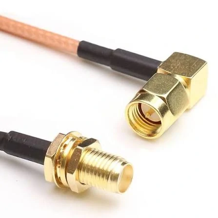
This image shows a standard SMA male to SMA female RF cable assembly. The assembly provides a reliable coaxial connection between RF modules, antennas, test equipment, and communication systems.
The connector end may get most of the attention, but the cable usually decides whether the assembly can actually fit the product.
A drawing may show enough space for an SMA connector. That does not always mean there is enough space for the cable behind it. RG316, RG174, RG178, RG402, RG405, 1.13 mm micro coax, and larger low-loss cables behave very differently during routing, stripping, crimping, soldering, and packaging.
A small cable solves space problems, but it may add attenuation, handling risk, and pull-force weakness. A larger low-loss cable reduces loss, but it needs more bend space and a connector body made for that diameter. A semi-rigid cable gives a stable RF path, but it does not forgive last-minute routing changes.
This is why cable selection should not be left as a supplier substitution. The cable model is part of the RF design.
Match RG316, RG174, RG178, RG402, RG405, or 1.13 mm cable to available space
RG316 is a common choice for short SMA jumpers because it is flexible, compact, and familiar to most RF cable assembly shops. It is often used in lab jumpers, GPS leads, Wi-Fi modules, and enclosure pigtails. The trade-off is loss. If the assembly becomes longer, the cable may become the bottleneck before the SMA connector does.
RG174 is also flexible and cost-sensitive, but it is not normally selected for a low-loss path. It works best where the cable is short and the RF requirement is not aggressive.
RG178 and 1.13 mm micro coax are useful when space is tight. They can route inside compact wireless modules, handheld devices, small antennas, and board-level RF paths. The risk is mechanical. These cables are easy to damage if the bend is too tight or if the assembly is pulled during installation.
For microwave fixtures, test adapters, and controlled internal RF routing, the cable shape may be part of the design. Once bent, it should not be treated like a soft jumper.
Larger low-loss RF cable helps when the antenna link is longer or the signal budget is tight. But it needs more routing room, a bigger connector body, and better strain relief. It may also be too stiff for small enclosures.
| Cable Option | Main Advantage | Limitation | Better For |
| RG316 | Flexible and compact | Higher loss than larger cable | Lab jumpers, GPS, Wi-Fi modules |
| RG174 | Cost-effective and flexible | Higher attenuation | Short RF links |
| RG178 | Small diameter | Limited power and distance | Compact devices |
| 1.13 mm coax | Very small routing space | Fragile, higher loss | Wireless modules |
| RG402 / RG405 | Stable RF path | Less flexible | Microwave fixtures |
| Low-loss cable | Lower attenuation | Larger bend space | Longer antenna links |
Choose shielding and jacket based on EMI, heat, and flex movement
Shielding is not only about “better signal.” It is about the environment around the cable.
Inside an RF enclosure, the cable may pass near DC power wiring, switching regulators, displays, motor drivers, or digital boards. A weak shield or poor braid contact can allow noise to enter the path. In antenna systems, poor shielding can also create unstable results when the cable position changes.
Jacket material matters too. A cable used near heat, soldering areas, or high-temperature equipment needs a jacket that can survive the environment. A cable used in a moving lid or hinged device needs flex life. A cable fixed inside a panel may need strain relief more than repeated flexibility.
For production, ask how the cable will be stripped and terminated. A small change in cable OD can change the ferrule, stripping length, soldering heat, and crimp tooling. That is where hidden batch variation starts.
How Can You Estimate Loss Before Finalizing Length?
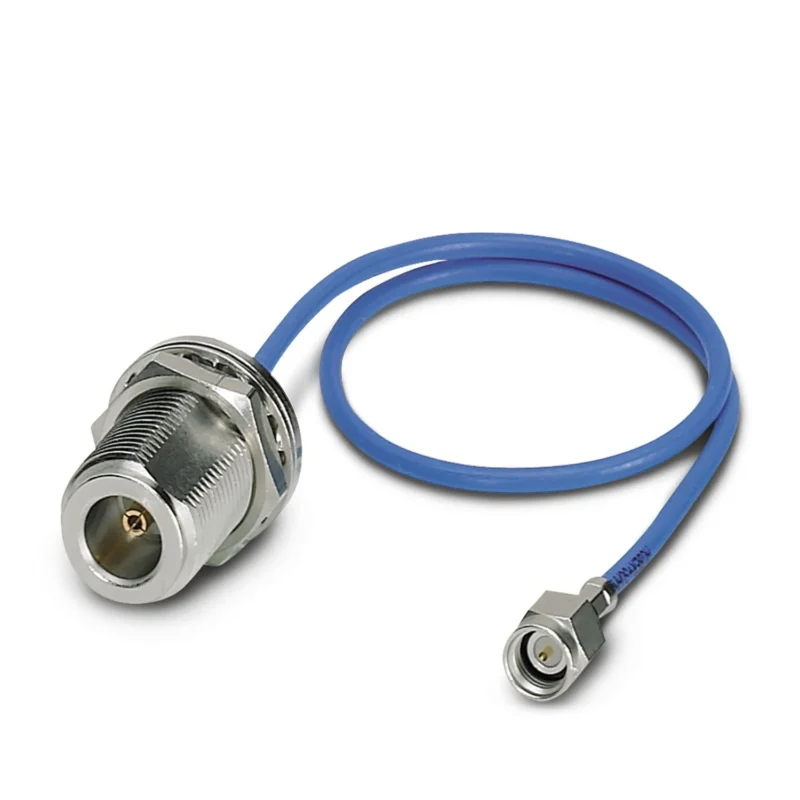
This image shows an SMA to N-type bulkhead cable assembly designed for RF signal transmission between different connector standards. It is suitable for antenna systems, wireless communication equipment, and RF testing applications
A cable assembly loss estimate does not need to be perfect to be useful.
It only needs to stop a bad decision early.
For example, a buyer may choose a thin flexible cable because it is easy to route. That may be fine for a short internal jumper. But if the same cable is used for a longer antenna lead, the loss may become unacceptable. The connector did not fail. The cable choice did.
The same problem appears when adapters are added casually. One adapter may be harmless in a rough prototype. Several adapters, plus a longer cable, plus a tight bend, can quietly consume margin.
Use cable attenuation and connector loss in one estimate
This is not a replacement for test data. It is a sourcing filter.
If the estimate is already too high, do not expect production testing to rescue the design. Change the cable, shorten the route, remove adapters, or adjust the system budget before ordering the batch.
| Field | Example Input |
| Cable Type | RG316 / RG174 / RG402 / low-loss coax |
| Target Frequency | GHz |
| Cable Length | m / inch |
| Cable Attenuation | dB/m |
| Connector Pair Loss | dB |
| Adapter Margin | dB |
| Bend / Routing Margin | dB |
| Estimated Total Loss | dB |
Compare a short flexible jumper against a longer low-loss assembly
A short RG316 SMA cable may be the right answer for a lab jumper or internal RF module lead. It is easy to bend, easy to package, and common in small assemblies.
A longer antenna cable is different. If the signal is weak, the frequency is higher, or the system has little margin, a larger low-loss cable may be more practical. The assembly becomes less convenient, but the RF result may be safer.
That trade-off should be discussed before the cable is produced. Once a thin cable is already built into a batch of assemblies, the only fix may be replacement.
How Should Bulkhead and Panel Routing Be Planned Inside Equipment?
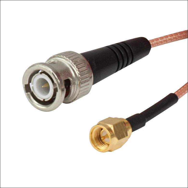
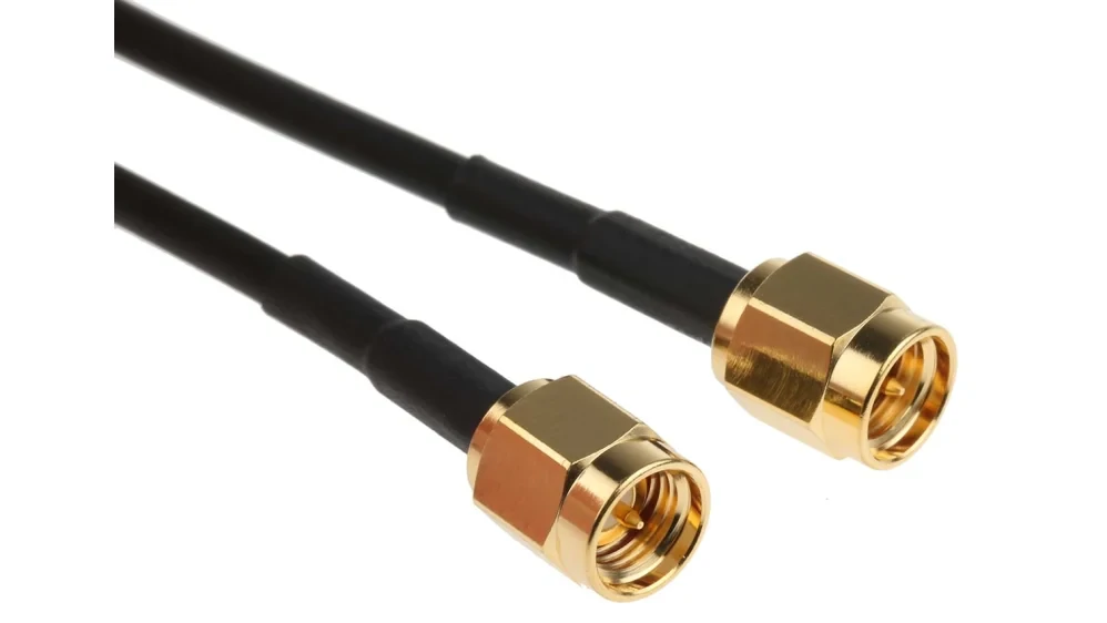
This image shows an SMA male to SMA male RF cable jumper assembly. It is commonly used in RF laboratories, wireless communication systems, antenna testing, and microwave equipment connections.
Bulkhead SMA assemblies look simple from the outside. The difficult part is usually inside the box.
The panel port may be fixed. The nut may tighten correctly. The outside appearance may look clean. But the inside cable can still exit toward the wrong direction, bend too sharply, or interfere with another component.
For panel-mounted RF ports, confirm the hardware before locking the cable length.
Route bulkhead pigtails from enclosure walls to RF boards
A bulkhead pigtail normally has one panel-mounted SMA end and one internal end. The internal end may be SMA, U.FL, MMCX, open wire for soldering, or another RF connector.
The outside port must match the customer-facing interface. The inside end must match the board or module. Both sides need to be confirmed. If the inside connector is tiny, such as U.FL or MMCX, the cable may need softer routing and better packaging protection.
Set bend radius and strain relief near SMA ports
Do not let the first bend start immediately at the connector body.
That bend can stress the termination area. In soft coax, it may deform the dielectric or loosen braid contact. In semi-rigid cable, it may create a shape that cannot be corrected without remaking the part.
Use heat shrink, clamps, or controlled cable routing when the assembly will be moved during installation. For production, a simple routing photo can be more useful than a long written note.
| Field | Required Detail |
| Outside Port | SMA female / SMA male / RP-SMA |
| Inside End | SMA / U.FL / MMCX / open end / PCB solder |
| Panel Thickness | mm / inch |
| Cable Exit Direction | Straight / right angle |
| Internal Cable Length | mm / inch |
| Bend Space | Enough / limited |
| Strain Relief | Heat shrink / clamp / none |
| Final Assembly Drawing | Required / optional |
How Should Coax Cable Diameter and Shielding Be Balanced?
The connector end may get most of the attention, but the cable usually decides whether the assembly can actually fit the product.
A drawing may show enough space for an SMA connector. That does not always mean there is enough space for the cable behind it. RG316, RG174, RG178, RG402, RG405, 1.13 mm micro coax, and larger low-loss cables behave very differently during routing, stripping, crimping, soldering, and packaging.
A small cable solves space problems, but it may add attenuation, handling risk, and pull-force weakness. A larger low-loss cable reduces loss, but it needs more bend space and a connector body made for that diameter. A semi-rigid cable gives a stable RF path, but it does not forgive last-minute routing changes.
This is why cable selection should not be left as a supplier substitution. The cable model is part of the RF design.
Match RG316, RG174, RG178, RG402, RG405, or 1.13 mm cable to available space
RG316 is a common choice for short SMA jumpers because it is flexible, compact, and familiar to most RF cable assembly shops. It is often used in lab jumpers, GPS leads, Wi-Fi modules, and enclosure pigtails. The trade-off is loss. If the assembly becomes longer, the cable may become the bottleneck before the SMA connector does.
RG174 is also flexible and cost-sensitive, but it is not normally selected for a low-loss path. It works best where the cable is short and the RF requirement is not aggressive.
RG178 and 1.13 mm micro coax are useful when space is tight. They can route inside compact wireless modules, handheld devices, small antennas, and board-level RF paths. The risk is mechanical. These cables are easy to damage if the bend is too tight or if the assembly is pulled during installation.
They are less about convenience and more about path stability. For microwave fixtures, test adapters, and controlled internal RF routing, the cable shape may be part of the design. Once bent, it should not be treated like a soft jumper.
Larger low-loss RF cable helps when the antenna link is longer or the signal budget is tight. But it needs more routing room, a bigger connector body, and better strain relief. It may also be too stiff for small enclosures.
| Cable Option | Main Advantage | Limitation | Better For |
| RG316 | Flexible and compact | Higher loss than larger cable | Lab jumpers, GPS, Wi-Fi modules |
| RG174 | Cost-effective and flexible | Higher attenuation | Short RF links |
| RG178 | Small diameter | Limited power and distance | Compact devices |
| 1.13 mm coax | Very small routing space | Fragile, higher loss | Wireless modules |
| RG402 / RG405 | Stable RF path | Less flexible | Microwave fixtures |
| Low-loss cable | Lower attenuation | Larger bend space | Longer antenna links |
Choose shielding and jacket based on EMI, heat, and flex movement
Shielding is not only about “better signal.” It is about the environment around the cable.
Inside an RF enclosure, the cable may pass near DC power wiring, switching regulators, displays, motor drivers, or digital boards. A weak shield or poor braid contact can allow noise to enter the path. In antenna systems, poor shielding can also create unstable results when the cable position changes.
Jacket material matters too. A cable used near heat, soldering areas, or high-temperature equipment needs a jacket that can survive the environment. A cable used in a moving lid or hinged device needs flex life. A cable fixed inside a panel may need strain relief more than repeated flexibility.
For production, ask how the cable will be stripped and terminated. A small change in cable OD can change the ferrule, stripping length, soldering heat, and crimp tooling. That is where hidden batch variation starts.
How Can You Estimate Loss Before Finalizing Length?
A cable assembly loss estimate does not need to be perfect to be useful.
It only needs to stop a bad decision early.
For example, a buyer may choose a thin flexible cable because it is easy to route. That may be fine for a short internal jumper. But if the same cable is used for a longer antenna lead, the loss may become unacceptable. The connector did not fail. The cable choice did.
The same problem appears when adapters are added casually. One adapter may be harmless in a rough prototype. Several adapters, plus a longer cable, plus a tight bend, can quietly consume margin.
Use cable attenuation and connector loss in one estimate
This is not a replacement for test data. It is a sourcing filter.
If the estimate is already too high, do not expect production testing to rescue the design. Change the cable, shorten the route, remove adapters, or adjust the system budget before ordering the batch.
| Field | Example Input |
| Cable Type | RG316 / RG174 / RG402 / low-loss coax |
| Target Frequency | GHz |
| Cable Length | m / inch |
| Cable Attenuation | dB/m |
| Connector Pair Loss | dB |
| Adapter Margin | dB |
| Bend / Routing Margin | dB |
| Estimated Total Loss | dB |
Compare a short flexible jumper against a longer low-loss assembly
A short RG316 SMA cable may be the right answer for a lab jumper or internal RF module lead. It is easy to bend, easy to package, and common in small assemblies.
A longer antenna cable is different. If the signal is weak, the frequency is higher, or the system has little margin, a larger low-loss cable may be more practical. The assembly becomes less convenient, but the RF result may be safer.
That trade-off should be discussed before the cable is produced. Once a thin cable is already built into a batch of assemblies, the only fix may be replacement.
How Should Bulkhead and Panel Routing Be Planned Inside Equipment?
Bulkhead SMA assemblies look simple from the outside. The difficult part is usually inside the box.
The panel port may be fixed. The nut may tighten correctly. The outside appearance may look clean. But the inside cable can still exit toward the wrong direction, bend too sharply, or interfere with another component.
For panel-mounted RF ports, confirm the hardware before locking the cable length.
Route bulkhead pigtails from enclosure walls to RF boards
A bulkhead pigtail normally has one panel-mounted SMA end and one internal end. The internal end may be SMA, U.FL, MMCX, open wire for soldering, or another RF connector.
The outside port must match the customer-facing interface. The inside end must match the board or module. Both sides need to be confirmed. If the inside connector is tiny, such as U.FL or MMCX, the cable may need softer routing and better packaging protection.
Set bend radius and strain relief near SMA ports
Do not let the first bend start immediately at the connector body.
That bend can stress the termination area. In soft coax, it may deform the dielectric or loosen braid contact. In semi-rigid cable, it may create a shape that cannot be corrected without remaking the part.
Use heat shrink, clamps, or controlled cable routing when the assembly will be moved during installation. For production, a simple routing photo can be more useful than a long written note.
| Field | Required Detail |
| Outside Port | SMA female / SMA male / RP-SMA |
| Inside End | SMA / U.FL / MMCX / open end / PCB solder |
| Panel Thickness | mm / inch |
| Cable Exit Direction | Straight / right angle |
| Internal Cable Length | mm / inch |
| Bend Space | Enough / limited |
| Strain Relief | Heat shrink / clamp / none |
| Final Assembly Drawing | Required / optional |
How Do You Define Test Limits for Production Assemblies?
A production SMA cable assembly should not be approved only because it looks clean.
Visual inspection catches obvious issues: loose nuts, damaged heat shrink, poor plating, wrong label, or a connector body that does not match the order. It does not prove RF behavior. A cable may pass continuity and still show high VSWR, unstable return loss, or higher-than-expected insertion loss at the working band.
The test plan should match the application. A short internal jumper for a low-risk device may only need continuity, short-circuit check, visual inspection, and length confirmation. A cable used in RF testing, antenna measurement, microwave fixtures, or repeat OEM production needs tighter limits.
Define continuity, VSWR, insertion loss, and return loss checkpoints
Continuity testing is the baseline. It confirms the center conductor path is connected and that the assembly is not shorted between center and shield. It does not confirm whether the cable is suitable at 2.4 GHz, 5.8 GHz, 6 GHz, or higher test bands.
VSWR and return loss help show mismatch. Insertion loss shows how much signal is lost through the cable assembly. For sensitive projects, the buyer should define the test frequency and pass/fail limit before production. Do not ask only for “low loss” or “good VSWR.” Those words are too loose for batch control.
| Inspection Item | Acceptance Requirement |
| Connector A / B | Matches order and approved sample |
| Cable Model | Confirmed before production |
| Length Tolerance | Defined in drawing or RFQ |
| Impedance | 50 ohm confirmed |
| Continuity | Pass |
| Short Circuit | No short between center and shield |
| VSWR | Tested if required |
| Insertion Loss | Recorded if required |
| Return Loss | Recorded if required |
| Visual Condition | No damage, loose parts, or poor shrink |
| Label / Packaging | Matches customer requirement |
Decide whether every piece or sample pieces need RF testing
Full RF testing is not always necessary. It also increases time and cost. For simple low-risk assemblies, sample inspection may be enough. For microwave test cables, antenna systems, or repeat OEM assemblies, 100% continuity plus defined RF sampling is safer.
If the cable will be used near the upper range of the connector or cable, do not rely on a basic pass/fail meter. Use a VNA sweep at the target frequency. Record the setup, adapters, calibration condition, and test limit. Otherwise, two suppliers may both say “tested,” but they may not mean the same thing.
Compare Standard, Low-Loss, and Microwave SMA Assemblies by Use Case
A standard SMA assembly is not worse than a low-loss or microwave assembly. It is just built for a different job.
For a short RF module jumper, the best design may be small, flexible, and easy to route. For a longer antenna cable, the priority shifts toward attenuation and shielding. For a microwave test fixture, repeatable geometry may matter more than softness.
| Use Case | Recommended Assembly Focus | Key Risk |
| RF module testing | Flexible SMA jumper | Repeated bending |
| Antenna connection | Lower-loss cable | Long cable attenuation |
| Enclosure port | Bulkhead pigtail | Hole size and bend clearance |
| VNA / lab fixture | Stable microwave cable | Connector wear |
| OEM device | Custom tested assembly | Batch consistency |
| Compact wireless module | Mini coax assembly | Fragile cable handling |
Compare flexible lab jumpers for short RF development work
Flexible SMA jumpers are convenient for early testing. They connect modules quickly, tolerate movement, and are easy to replace. The weak point is repeat bending. If the cable is pulled, twisted, or used as a handle, the termination area may fail before the connector interface looks damaged.
For lab use, label the cable type and length. Keep test jumpers separate from production samples. A worn lab cable should not become the reference for an OEM drawing.
Compare low-loss cable assemblies for longer antenna links
A low-loss cable assembly is useful when distance starts to matter. Outdoor antenna runs, cabinet-to-antenna connections, and higher-frequency wireless links may need a cable larger than RG316 or RG174.
The trade-off is mechanical. A thicker cable needs a larger connector body, more bend room, stronger strain relief, and better packaging. If the enclosure cannot accept the cable bend radius, the low-loss choice may create an installation problem.
When Should a Standard SMA Cable Become a Custom Assembly?
A standard cable becomes risky when the installation no longer matches a standard cable.
That may happen when the off-the-shelf length creates loops, when the connector points the wrong way, when a bulkhead end must fit a fixed panel, or when the same cable must be repeated in monthly production.
Custom does not always mean complicated. It may simply mean a fixed length, confirmed cable type, marked packaging, and approved connector orientation.
Move to custom length when off-the-shelf routing creates loops
Extra cable length looks harmless until it is forced into a tight enclosure. A loop can press against a shield, touch a hot area, or pull on the connector after the cover is closed. Shortening the cable to the real route often improves both installation and repeatability.
Customize connector orientation when enclosure clearance is limited
Right-angle, straight, and bulkhead ends should be selected from the real layout. A right-angle connector can solve a height problem, but only if it points in the correct direction. For tight designs, send a photo or drawing before ordering.
How Do You Send a Complete SMA Assembly RFQ?
A complete RFQ saves time because it removes guessing.
Use a port-to-port description, then add the operating condition and inspection need.
| RFQ Field | Example |
| Connector A | SMA male straight |
| Connector B | SMA female bulkhead |
| Cable Type | RG316 / RG174 / RG402 / custom |
| Length | 100 mm / 300 mm / 1 m |
| Impedance | 50 ohm |
| Frequency Range | DC–3 GHz / DC–6 GHz / higher |
| Test Requirement | Continuity / VSWR / insertion loss |
| Application | Antenna / module / test fixture |
| Quantity | Sample / batch |
| Drawing or Photo | Required for replacement |
FAQ
How do I describe an SMA cable assembly when both ends look similar?
Use a port-to-port description. For example: “SMA male straight to SMA female bulkhead, RG316, 300 mm, 50 ohm.” Add photos of both mating ports if the gender or polarity is uncertain.
When is RG316 acceptable for an SMA cable assembly?
RG316 is suitable for many short and flexible RF jumpers, especially inside compact devices, GPS products, Wi-Fi modules, and lab setups.
Should an SMA cable assembly use straight or right-angle connectors?
Use straight connectors when there is enough routing space behind the port. Use right-angle connectors when height or exit direction is limited. Always confirm the direction before production.
Does an SMA bulkhead pigtail count as a cable assembly?
Yes. A bulkhead pigtail is a cable assembly with one panel-mounted SMA end and another internal end, such as SMA, U.FL, MMCX, open end, or PCB solder type.
What test data should I request for production SMA cable assemblies?
At minimum, request continuity and short-circuit inspection. For RF-sensitive work, add VSWR, insertion loss, return loss, test frequency, and pass/fail limits.
Why can two SMA cable assemblies with the same length perform differently?
They may use different cable types, shielding, connector bodies, plating, termination processes, bend radius, or test frequency. Same length does not guarantee the same RF performance.
