
A cable assembly can pass continuity and still be wrong for the RF path.
That is a common problem in cable purchasing. The connector fits. The center pin looks normal. The cable is the requested length. A quick DC check shows no open circuit. Then the assembly is placed into a 2.4 GHz antenna path, a 6 GHz test fixture, or a microwave module setup, and the measured power drops more than expected.
Nothing dramatic failed. The signal simply lost more power through the added path.
That loss is usually described as insertion loss. In RF cable testing, it is not just a cable number. It can come from the coaxial cable, connector interfaces, adapter transitions, termination quality, bend radius, mating condition, and operating frequency. A short jumper at low frequency may hide these problems. A longer cable, tighter routing, or extra adapter stack may expose them quickly.
Why Does Insertion Loss Change RF Cable Results?
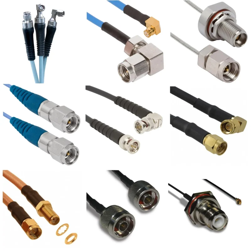
Insertion loss describes how much signal power is reduced after a component is inserted into the RF path. For a cable assembly, that path usually includes two connectors, the cable body, the termination area, and sometimes one or more adapters.
The sourcing mistake is treating this whole path as “just a cable.”
The cable body creates length-related loss. Higher frequency, longer cable, smaller conductor, dielectric material, and shielding structure all affect attenuation. But the connector ends also matter. A poor interface, loose mating, wrong cable fit, weak braid contact, or damaged center pin can add loss or create mismatch. If an adapter is added, the signal passes through another mechanical interface. That interface may be useful, but it is not invisible.
This is why two cable assemblies with the same connector names and same length may not test the same. One may have the correct ferrule, stable center pin alignment, clean crimping, and suitable cable construction. Another may look similar in a product photo but use a less stable termination or a connector body that does not match the cable diameter well.
At low frequency, the difference may be small. Near the upper working band, it may appear as higher insertion loss, unstable VNA readings, worse return loss, or signal margin that disappears after final installation.
It tells the supplier the interface and length, but not the RF requirement. A better request should include cable type, impedance, frequency range, connector combination, maximum insertion loss if needed, and test report requirements.
This does not make the cable automatically low loss. It simply removes guesswork. The supplier now knows what the assembly must be checked against.
Where the loss appears in a cable assembly
Insertion loss rarely comes from one place only. It is better to break the path into smaller risk points.
| RF Path Area | What Can Add Loss | Practical Warning Sign |
| Cable body | Long length, higher frequency, smaller conductor, lossy dielectric | Output power is lower than expected |
| Connector interface | Poor mating, worn contact, unstable geometry | Reading changes after reconnecting |
| Termination area | Weak crimp, solder heat damage, poor braid contact | Batch result varies |
| Adapter transition | Extra interface and impedance discontinuity | Loss increases after conversion |
| Installation route | Tight bend, crushed cable, routing stress | Result changes after assembly |
This table matters because many buyers only compare the cable model. That is useful, but incomplete. A datasheet may show attenuation for the cable under controlled conditions. The finished assembly includes connectors, processing, handling, routing, and customer-specific length.
A product such as an SMA cable assembly for RG316, RG58, RG142, RG402, or RG405 should be judged as a complete RF part. The front interface alone does not decide performance. Rear body size, ferrule fit, dielectric support, braid contact, soldering or crimping method, and final inspection all affect the result.
Visual inspection can catch obvious problems. It cannot prove high-frequency behavior.
How Can Engineers Separate Cable Loss From Connector Loss?
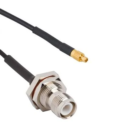
This image shows an RF cable assembly using N type and SMA connectors. Connector quality, cable construction, and termination workmanship can affect insertion loss performance in RF systems.
The practical question is not only, “How much loss does this cable have?” A better question is, “Where does this RF path lose signal?”
Start with cable attenuation. Cable attenuation normally increases as frequency rises. It also increases with length. A 100 mm jumper and a 3 m antenna cable should not be treated like the same part just because both are 50 ohm coaxial cables.
Then check connector and adapter contribution. Connector loss is affected by interface quality, frequency rating, mating condition, plating, geometry, and assembly workmanship. Adapter loss is often underestimated because adapters look small and convenient. In a lab, one adapter may be acceptable. In production, multiple adapters may create avoidable loss and mismatch.
Adapters are not the enemy. They are useful for prototypes, temporary test benches, and mixed-interface systems. The problem starts when they are ignored in the loss expectation.
That sentence gives the supplier a measurable target. It also prevents a common dispute: the cable mates correctly, but the customer later says the signal is weak. Without a written insertion loss target, both sides are discussing expectations instead of data.
Continuity testing is still useful. It confirms the basic electrical connection. But it does not prove RF insertion loss, VSWR, or return loss. For critical antenna cables, test cables, microwave jumpers, or production assemblies used near the upper frequency range, a VNA sweep or cable analyzer test is the safer inspection method.
Calculate Total Insertion Loss Before Ordering
A cable drawing is not enough when the RF path has a loss limit.
Length, connector type, and cable model are useful, but they do not tell the buyer whether the finished assembly will stay inside the system budget. For a short internal jumper, that may not matter much. For an antenna feed, RF test cable, microwave module connection, or production fixture, the estimated loss should be checked before the order is released.
This is not meant to replace actual VNA testing. It is a sourcing filter. It helps catch weak cable choices before samples are built.
If a cable datasheet gives attenuation in dB per 100 meters, divide it down to the project length. If it gives dB per foot, use the installed length in feet. The value must be taken at the target frequency or near it. A cable that looks acceptable at 100 MHz may not behave the same at 3 GHz, 6 GHz, or higher.
Use an RF path estimate table before sampling
For RF purchasing, the estimate does not need to be beautiful. It needs to be clear enough that engineering, sourcing, and the supplier are discussing the same path.
| Field | What to Enter | Why It Matters |
| Frequency | 1 GHz, 3 GHz, 6 GHz, or operating band | Loss changes with frequency |
| Cable Model | RG316, RG58, RG142, RG402, RG405, LMR series | Cable construction sets the base attenuation |
| Cable Length | Total finished length | Longer cable adds more loss |
| Connector A / B | SMA, BNC, N, MMCX, MCX, TNC, etc. | Interface and rating affect the result |
| Adapter Count | 0, 1, 2, or more | Each transition can add loss and mismatch |
| Test Limit | Maximum allowed dB value | Gives the supplier a measurable target |
This table is more useful than asking for a “low loss RF cable” without context. Low loss compared with what? At what frequency? At what length? With how many adapters? Those missing details cause many RFQ problems.
For example, an RG316 jumper may be fine for a short internal connection where flexibility matters. The same cable may be a poor choice for a longer external antenna run if the system has little margin. RG58 may reduce loss compared with smaller cable in some cases, but it also takes more space and needs the correct connector rear body. Semi-rigid or semi-flexible cable may help in microwave layouts, but it changes installation handling.
The better comparison is not cable name against cable name. It is finished path against finished path.
Option C may look easier for purchasing because adapters solve interface problems quickly. Electrically, it may be the weakest path.
How Do Frequency, Length, and Bend Radius Change Loss?
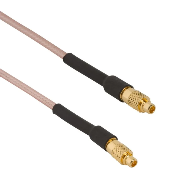
Frequency changes the rules quietly.
At lower frequencies, a cable assembly may tolerate small imperfections without creating an obvious field problem. As frequency rises, the RF path becomes less forgiving. Cable attenuation rises. Connector geometry matters more. Small discontinuities can show up in insertion loss, return loss, or ripple across the sweep.
This is why a cable that works in one project should not be copied blindly into another. A 50 ohm assembly used for a low-frequency control signal is not automatically suitable for a 5.8 GHz antenna link or a microwave test setup. The impedance label is only one part of the story.
Length is easier to understand. More cable means more loss. Still, buyers often underestimate it because cable assemblies are ordered by convenience. A design may start with a 300 mm sample on the bench. Later, the installed product needs 1.5 m to reach the antenna position. If the cable type stays the same, the loss rises. If the installation also adds bends and adapters, the final result may move outside the expected margin.
Bend radius is the mechanical detail that gets ignored until testing becomes unstable.
A coaxial cable is not just a wire inside plastic. Its geometry controls impedance. If the cable is bent too tightly, crushed under a cover, pulled at the connector exit, or routed against a sharp metal edge, the internal spacing can change. Shield contact may also be stressed. The result may not be visible from outside, but the RF sweep can change.
Practical risk map for frequency and installation
| Condition | Loss Risk | What to Check Before Ordering |
| Low frequency, short cable, direct connection | Low | Basic cable type and connector fit |
| Higher frequency, short cable | Medium | Connector rating, termination quality, VNA sweep if needed |
| Long cable run | Medium to High | Cable attenuation at target frequency |
| Long cable plus adapters | High | Total path loss and return loss |
| Tight bend near connector | High | Bend radius, strain relief, repeatability |
| Microwave assembly | High | Cable construction, connector geometry, full sweep test |
A cable may pass when it is straight on the bench and fail after it is installed. That is not unusual. The bench condition is clean. The installed condition has routing pressure, panel holes, nearby modules, repeated handling, and sometimes waterproof parts or heat-shrink strain relief.
Those mechanical details should be discussed before production, not after the first failed batch.
How Should RF Cables, Connectors, and Adapters Be Compared?
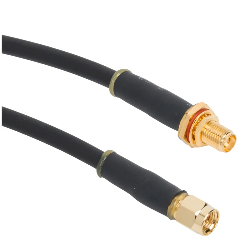
Do not compare RF parts one item at a time if they will be used as one path.
A connector with a higher frequency rating does not automatically make the assembly low loss. A low loss cable does not rescue a poor adapter stack. A good cable drawing does not prove stable assembly workmanship. The final path is the thing that should be compared.
For cable assemblies, compare these four points first:
| Comparison Point | Weak RFQ | Better RFQ Detail |
| Cable | “Coax cable” | RG316 / RG58 / RG142 / RG405 / LMR type |
| Connector | “SMA connector” | SMA male, 50 ohm, straight or right angle, cable-matched body |
| Frequency | Not stated | Working band or test frequency |
| Loss requirement | “Low loss” | Maximum insertion loss at target frequency |
Adapters should be treated as a separate decision. If an adapter is only needed for a temporary test bench, it may be acceptable. If the same conversion will remain in production, an integrated adapter cable or direct cable assembly may be cleaner.
That does not always reduce loss by itself, but it removes one mated interface and simplifies inspection. It also gives the supplier a chance to build the correct cable, connector bodies, and length as one controlled assembly.
TEJTE’s RF adapter cable category can be used when the final product needs mixed interfaces without building a long chain of separate adapters.
The most useful buying habit is simple: specify the complete RF path, not only the part name.
Write the cable type. Write the connector interfaces. Write the impedance. Write the length. Write the working frequency. Add the maximum insertion loss if the system depends on it. Request VNA data when the application is sensitive.
That gives engineering something to verify, purchasing something to compare, and the supplier something real to build against.
How Can Low Loss Cable Choices Reduce Insertion Loss?
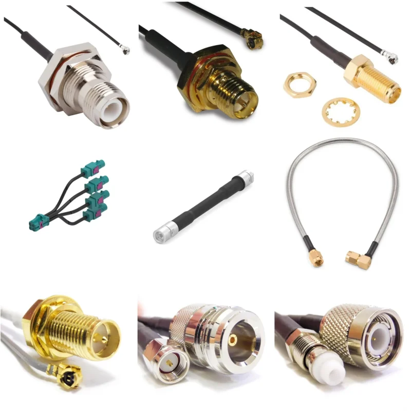
Low loss cable helps, but it does not fix every RF path problem.
That point matters because “low loss” is often used too loosely in RF purchasing. A larger cable, foamed dielectric, better shielding, or lower attenuation construction can reduce cable body loss. Still, the finished assembly can test poorly if the connector is not matched to the cable, the bend radius is too tight, or the adapter chain is doing too much work.
Start with the actual signal path. A short internal jumper inside a compact wireless module may need flexibility more than the lowest possible attenuation. A 3 m antenna cable may need lower loss construction because length becomes the dominant problem. A microwave test jumper may need stable phase and repeatable bending behavior, not only a nice attenuation number on paper.
Cable diameter is one of the first trade-offs. Larger coaxial cable often gives lower attenuation, but it also needs more installation space and different connector bodies. A buyer cannot simply replace RG316 with RG58, or RG58 with a thicker low loss cable, without checking the connector rear structure, ferrule size, bend space, and enclosure exit point.
A practical selection view looks like this:
| Cable Choice Factor | What It Affects | Buyer Note |
| Cable length | Total attenuation | Longer runs need stricter loss review |
| Cable diameter | Loss, flexibility, connector fit | Do not change cable size without checking connector body |
| Dielectric material | Frequency behavior and attenuation | Check data at the operating frequency |
| Shielding | Leakage, stability, handling | Important near noise sources or in test setups |
| Bend radius | Impedance stability | Tight routing can change the measured result |
| Connector match | Final assembly repeatability | Cable-compatible connector parts are required |
That gives the supplier room to propose RG58, RG142, LMR-type cable, semi-flexible cable, or another option based on the real limit. It also avoids pretending that one cable type is always the correct answer.
Build an RF Test Plan for Insertion Loss
The test method should match the risk level.
For many ordinary cable assemblies, continuity testing, visual inspection, and dimensional checks may be enough. For loss-sensitive RF paths, that is not enough. A continuity test only proves that the center conductor and shield are electrically connected. It does not prove insertion loss, VSWR, return loss, or stability across frequency.
A VNA sweep is the common method for checking finished RF cable insertion loss. A cable and antenna analyzer may also be used depending on the frequency range and test purpose. The key is to test across the working band, not only at one convenient point.
If the product works from 700 MHz to 2.7 GHz, then a single 1 GHz result does not describe the whole path. If the assembly is used near 6 GHz, the test should include the upper band. The worst point may not be at the frequency the buyer expects. Cable loss, connector mismatch, and adapter transitions can create ripple across the sweep.
A simple test record can prevent later arguments:
| Test Field | Required Value |
| Cable Part Number | Model or customer drawing number |
| Connector A / B | SMA / BNC / N / MMCX / MCX / custom |
| Cable Type | RG316 / RG58 / RG142 / RG405 / LMR series |
| Length | Finished length including tolerance |
| Frequency Range | Start and stop frequency |
| Test Method | VNA or cable analyzer |
| Insertion Loss Limit | Maximum allowed dB value |
| VSWR / Return Loss | Optional acceptance value |
| Result | Pass / Fail, with test date |
The test environment also matters. If the supplier tests the cable with one adapter set and the customer tests with another, small differences may appear. For critical projects, the RFQ should define whether the value applies to the cable assembly only or to the assembly plus supplied adapters.
How Should Acceptance Limits Be Written on RFQs?
Write the acceptance limit in a way that can be tested.
“Low insertion loss” sounds useful, but it is not a measurable requirement. “Good signal” is worse. A supplier cannot inspect against those phrases, and a buyer cannot use them to judge a batch fairly.
If VSWR or return loss matters, add it separately. Do not hide everything under insertion loss. High insertion loss and poor return loss are related in some cases, but they are not the same measurement.
This does not force unnecessary testing on every simple order. It only makes the requirement clear when RF performance is part of the buying decision.
FAQ
Why does insertion loss matter in RF cable assemblies?
Insertion loss shows how much signal power is lost after the cable assembly is added to the RF path.
Is insertion loss the same as cable attenuation?
Not exactly. Cable attenuation usually refers to loss from the coaxial cable body itself. Insertion loss for a finished assembly can include cable attenuation, connector loss, adapter loss, termination quality, and mismatch effects. That is why a finished cable assembly should not always be judged only by the cable datasheet.
How can I estimate RF cable insertion loss before ordering?
Use the cable attenuation value at the target frequency, multiply it by the required cable length, then add estimated connector and adapter loss. This estimate is not a replacement for VNA testing, but it helps compare cable options before sampling.
Why does insertion loss increase at higher frequencies?
Higher frequencies are more sensitive to conductor loss, dielectric loss, connector geometry, and impedance discontinuity. A cable that performs acceptably at low frequency may show more loss or ripple when tested near the upper operating band.
Can low loss RF cable remove insertion loss completely?
No. A low loss RF cable can reduce cable attenuation, but every real RF path still has some loss. Connectors, adapters, termination points, and installation routing all affect the final assembly result.