
The cable looked normal.
Both SMA connectors were tight, continuity passed, and the assembly length matched the drawing. Nothing obvious suggested a problem. Then it went on the VNA.
At the target frequency, S21 was about −2.6 dB. The project limit was 1.5 dB.
That changes the discussion quickly. A cable assembly can be electrically connected and still lose too much RF power. Continuity testing will not catch that. Neither will a visual inspection.
This is where insertion loss becomes useful. It gives engineers a way to judge how much transmission is being lost between defined points in an RF path. For a finished cable assembly, the measured number may include more than the cable itself. Connectors, terminations, adapters, bends, and even the way the measurement is set up can move the result.
That last point causes plenty of confusion. Two suppliers can test what appears to be the same assembly and report different loss values simply because they did not measure from the same reference planes.
So before deciding that a cable is “too lossy,” first ask a more practical question: what exactly was included in the test?
Where Does Insertion Loss Occur in an RF Signal Path?
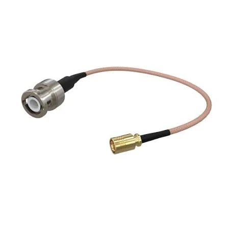
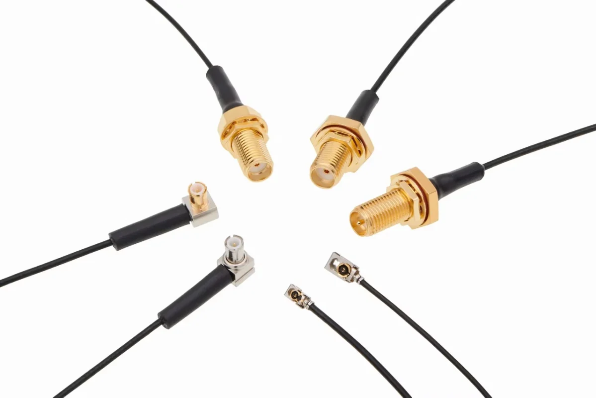
BNC-to-SMA RF coaxial cable assembly for connecting compatible RF instruments, test equipment, and communication devices. Verify connector interfaces, cable impedance, operating frequency, and insertion loss requirements before selecting an assembly.
A real RF path is rarely just one piece of coax.
Take a short antenna lead inside a wireless device. The signal may leave the RF module, pass through a board connector, enter a coaxial cable, cross another connector, and finally reach an antenna or bulkhead interface. A test setup may add one or two adapters on top of that.
Each transition changes the transmission path.
The cable normally contributes the largest predictable part of the loss when the run becomes longer. The connectors and adapters usually contribute less individually, but their effect becomes harder to ignore as the frequency rises or the number of interfaces increases.
There is another problem: not all loss is caused by the same mechanism.
Inside the cable, conductor and dielectric losses reduce the transmitted signal. At a connector, geometry changes and imperfect impedance transitions may introduce both transmission loss and reflection. At a termination, poor braid contact, soldering damage, or a center pin sitting too far forward or backward can make an otherwise correct connector behave badly.
The assembly may still look fine from the outside.
Trace the Whole Path Before Blaming the Cable
A useful habit in the lab is to write down every part between the calibrated ports.
If calibration was performed only at the VNA test-cable ends, those adapters may be part of the measured result.
Remove one adapter and the loss may improve. That does not automatically mean the cable assembly changed. The measurement path changed.
This becomes especially relevant with production testing. A prototype may have been measured directly with SMA test cables, while the production line later uses extra N-to-SMA adapters because that fixture is easier to operate. Comparing the two readings without documenting the setup creates a false quality problem.
The same issue appears during supplier comparison. A difference of several tenths of a decibel may come from the DUT. It may also come from cables, adapters, calibration drift, connector wear, or reference-plane placement.
That is why a useful insertion loss report needs more than one number.
Cable Attenuation Is Not the Same as Assembly Insertion Loss
Cable manufacturers normally publish attenuation at selected frequencies, often as dB per meter or dB per 100 feet.
That data is useful for estimating the cable portion of the RF loss. It does not automatically describe a finished assembly.
A 2 m cable assembly includes two terminations. If adapters are required during the test, the test path may include those as well.
The distinction is simple but important:
| Item | What the value normally represents |
| Cable attenuation | Loss per unit length of the coaxial cable at a stated frequency |
| Connector loss | Contribution from a connector or interface under defined conditions |
| Cable assembly insertion loss | Measured transmission loss of the finished assembly between selected reference planes |
| System path loss | Combined loss from all included RF components and transitions |
This is also why cable selection cannot be separated from connector selection.
An SMA interface on the front does not tell you whether the rear termination fits RG316, RG58, RG142, or another cable. The ferrule, center contact, dielectric support, and cable dimensions still need to match.
A part can mate correctly and still be the wrong part for the assembly.
For buyers, this is worth checking before approving a substitution. If the original BOM calls for RG58 and the alternate connector was designed around a much smaller cable, “SMA male” is not enough information to approve it.
The same logic applies to attenuation data. Compare cable loss at the actual operating frequency, not just at a convenient point on the datasheet.
How Do You Calculate Insertion Loss From Power or S21?
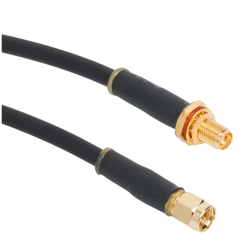
There are two common ways engineers run into insertion loss: from input/output power and from VNA S21 data.
Suppose 100 mW enters a defined RF path and 63 mW is available at the output under the same reference conditions.
The calculated insertion loss is about 2.0 dB.
That does not mean “2% of the power disappeared.” Decibels are logarithmic. A 2 dB loss leaves roughly 63% of the original power.
The calculation is straightforward. The test conditions are usually the part that needs more attention.
Why Does a VNA Show Negative S21?
This is a common source of confusion for technicians who are new to network-analyzer measurements.
So an S21 reading of −0.8 dB is usually discussed as 0.8 dB insertion loss.
There is no need to make the sign more complicated than it is. The VNA is showing transmission relative to its reference level. A passive path transmits less than the reference, so the displayed value is negative.
The more useful question is what the trace does across frequency.
A cable that measures −0.7 dB at 500 MHz may not remain near −0.7 dB at 3 GHz or 6 GHz. Cable attenuation generally rises with frequency, and poor transitions may produce additional ripple.
A single marker can therefore hide the real problem.
When checking an RF cable assembly, sweep the operating band and look at the shape of the S21 trace. A smooth rise in loss and a sharp local dip are not the same symptom. Neither should be diagnosed from the number alone.
That is where the measurement starts becoming useful—not simply as a pass/fail value, but as evidence about what is happening inside the RF path.
How Do Frequency and Cable Length Change the Measured Loss?
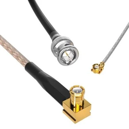
Custom RF coaxial cable assemblies with BNC and miniature RF connector interfaces. Connector compatibility, cable construction, and termination quality should be considered when evaluating insertion loss and signal transmission performance.
A cable that looks acceptable at 500 MHz may become the weak point at several gigahertz.
That is not unusual. Coaxial cable attenuation changes with frequency, and longer cable simply gives that loss more distance to accumulate.
The formula is useful, but only if the attenuation value comes from the correct frequency.
Using a 100 MHz attenuation figure to estimate loss at 3 GHz is not a shortcut. It is the wrong input.
Use the Actual Frequency, Not a Single Catalog Number
Cable datasheets normally list attenuation at several frequencies. Some also provide curves.
That matters because RF cable loss is not flat.
A sourcing mistake we see often is comparing two cable families only by diameter or impedance. Both may be 50 ohm. Both may accept an SMA connector. Their attenuation at the upper end of the band can still be quite different.
RG316, RG58, and larger low-loss cable families are a good example.
A small cable such as RG316 is convenient when routing space is tight. RG58 gives a larger construction and different mechanical behavior. An LMR-type low-loss cable may be selected where the RF run is longer and attenuation becomes more important.
There is no useful universal statement such as “RG58 loses X dB per meter.” The number depends on frequency and the actual cable specification.
Use the manufacturer’s data for the cable being purchased.
| Selection question | What to check |
| Operating frequency | Attenuation at or near the highest required frequency |
| Cable length | Finished assembly length, not just a rough routing estimate |
| Cable family | Actual manufacturer specification or approved equivalent |
| Connector fit | Rear termination dimensions must match cable construction |
| Installation route | Bend radius, strain, and available space |
The table is simple, but it prevents a common procurement problem: selecting the cable first and checking the RF loss only after samples arrive.
Shorter Is Not Always Better
Reducing cable length usually reduces cable attenuation.
That does not mean the shortest possible assembly is automatically the best installed design.
A cable cut too short may be pulled sideways at the connector. It may need a tighter bend to reach the mating port. During installation, the assembler may force the cable into position and load the connector body mechanically.
None of those conditions appear in a basic attenuation calculation.
This is why cable length should be treated as both an RF parameter and a mechanical parameter.
An extra few centimeters may add a small amount of loss, but it can also produce a much cleaner routing path. The correct trade-off depends on the frequency, allowable loss budget, cable type, and enclosure geometry.
For production assemblies, test the length that will actually be installed.
Do not qualify a 20 cm engineering sample and assume the 80 cm production version will behave the same.
How Much Loss Comes From Connectors and RF Transitions?
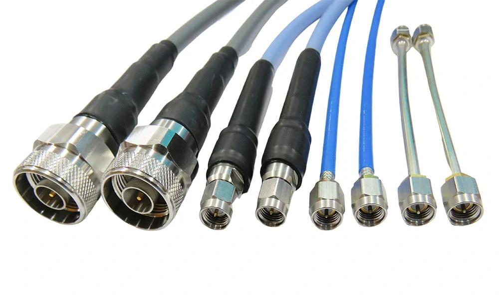
RF coaxial cable assemblies featuring different connector interfaces and cable types. Selecting compatible connectors and cables helps maintain impedance matching and control insertion loss across the intended operating frequency range.
Connectors are easy to blame because they are visible.
The cable is hidden under the jacket. The SMA, BNC, TNC, or N-Type interface sits directly in front of the technician, so any unexpected loss is often described as “connector loss.”
That diagnosis may be too simple.
A connector can contribute to insertion loss, but the finished transition includes more than the mating interface.
The center contact position matters. So does the dielectric geometry, braid connection, ferrule compression, solder joint, cable preparation length, and the condition of the mating connector.
Do Not Assign One Fixed Loss Value to Every Connector
There is no useful rule that says every SMA connection adds a fixed number of decibels.
The result changes with frequency and construction.
A well-made connector transition at a relatively low operating frequency may contribute very little to the total path loss. The same physical area can become more sensitive when frequency rises or the termination geometry is poor.
Adapters make the situation more complicated.
Suppose an assembly needs two adapters to fit the test setup. Now there are additional interfaces, and each one becomes part of the measured path unless calibration or de-embedding removes it.
That does not make adapters “bad.” It means they need to be accounted for.
Stacking adapters casually is a different matter.
An SMA-to-BNC adapter followed by another BNC-to-N transition may solve a bench connection problem, but it also adds more mechanical interfaces and more opportunities for mismatch.
For troubleshooting, simplify the path before replacing the cable.
Separate Connector Design From Termination Quality
Two assemblies can use the same connector model and still produce different S21 results.
The difference may be in assembly workmanship.
Typical points worth checking include:
- center pin not fully seated
- solder wicking too far into the cable
- dielectric damaged by excessive heat
- braid cut too short
- incomplete shield contact under the ferrule
- ferrule crimped with the wrong tool size
- cable jacket or dielectric deformed near the termination
Some defects are visible. Others are not.
This is why a supplier should not rely only on continuity and appearance for an RF cable assembly intended for higher-frequency work.
A visually clean termination can still produce poor RF behavior.
How Do You Measure Insertion Loss With a VNA?
Define the DUT Before Calibration
Decide what is being tested.
Is the DUT:
- the coaxial cable only?
- a finished cable assembly?
- an adapter?
- a bulkhead transition?
- a cable assembly plus fixture?
That decision should be made before calibration, not after the measurement looks suspicious.
For most finished RF cable assemblies, the useful result is the transmission between the two assembly interfaces.
The VNA is then calibrated so the measurement reference planes are placed as close as practical to those interfaces.
If additional adapters remain between the calibrated port and the DUT, document them.
Keep the Test Cables Still
This sounds basic. It is also easy to ignore.
After calibration, moving or sharply bending flexible VNA test cables can change the measured response.
That becomes more noticeable when the test system is working near its repeatability limit.
A technician may calibrate with the cables lying flat, then lift one cable and twist it around the DUT during testing. The result now includes another variable.
Secure the setup first. Then connect the DUT with as little disturbance as possible.
Sweep the Operating Band
Do not judge the assembly from one marker unless the specification is truly single-frequency.
A frequency sweep gives much more information.
Look for:
- expected gradual increase in cable loss
- sudden dips
- excessive ripple
- unstable readings after reconnecting
- large differences between supposedly identical assemblies
A smooth curve that is slightly above the limit suggests a different problem from a narrow, sharp loss feature.
But the trace alone does not prove the root cause.
It tells you where to investigate.
For production work, record the frequency range, calibration method, fixture or adapter configuration, cable position, and the acceptance limit along with the S21 result.
Otherwise, the same cable may be “good” on one bench and “bad” on another simply because nobody documented how it was measured.
How Can You Separate Insertion Loss From Return Loss?
Insertion loss and return loss often appear on the same VNA screen, but they answer different questions.
Insertion loss is concerned with forward transmission. For a two-port cable assembly, engineers normally look at S21.
Return loss deals with reflection. At Port 1, that normally means S11. At Port 2, the corresponding measurement is S22.
A cable can look good on one measurement and still cause trouble on the other.
Consider a long, well-matched coaxial cable. Its return loss may be acceptable because the impedance remains close to the intended system impedance. The cable can still have substantial insertion loss simply because conductor and dielectric losses accumulate over its length.
The opposite situation is also possible. A short cable may have low attenuation, but a poor termination can create a noticeable impedance discontinuity.
That may disturb both S21 and return loss.
| Measurement | Main question | Typical VNA parameter |
| Insertion loss | How much transmission is lost through the DUT? | S21 |
| Return loss | How much signal is reflected at the port? | S11 / S22 |
| VSWR | How severe is the impedance mismatch? | Derived from reflection |
VSWR is useful here, but it should not replace an insertion loss test. It describes mismatch, not the total transmitted power loss through the assembly.
For troubleshooting, looking at S21 and S11 together is often more useful than trying to diagnose a cable from either trace alone.
How Should You Investigate Unexpectedly High Insertion Loss?
Do not start by cutting the connector off.
First repeat the measurement.
Unexpected loss is sometimes caused by the DUT. Sometimes it is the bench.
Check the VNA calibration status, test-cable position, adapter condition, and reference planes before changing the assembly. Reconnect the DUT once and see whether the result is repeatable.
If a cable measures 1.2 dB, then 1.8 dB, then 1.3 dB without any physical change to the assembly, the test setup deserves attention.
Once repeatability is confirmed, compare the result with the expected cable baseline.
If the cable alone should account for most of the measured loss, the number may be reasonable. If a short assembly measures far above the expected cable attenuation, inspect the transitions.
Useful checks include:
- center contact position
- contamination or damaged mating surfaces
- braid contact under the ferrule
- incomplete crimping
- excessive solder
- dielectric heat damage
- local cable crushing
- bend radius near the connector
- unexpected adapters in the path
Installed condition matters as well.
A cable may test normally while lying straight on a bench, then change after it is bent tightly into an enclosure. If the real installation includes a fixed bend or strain point, test that condition instead of qualifying only the relaxed cable.
Frequency behavior provides another clue.
A smooth rise in loss across frequency often points toward normal cable attenuation or a general loss increase. Strong ripple or a narrow abnormal feature suggests that mismatch or a localized transition may also be involved.
It is evidence, not a final diagnosis.
How Can You Build an RF Insertion Loss Budget?
A useful loss budget starts before the cable is ordered.
The goal is not to predict the final VNA result to the second decimal place. It is to check whether the selected cable, length, interfaces, and project limit make sense together.
RF Cable Insertion Loss Budget Matrix
| Budget field | Value to record |
| Operating frequency | MHz / GHz |
| Cable model | RG316 / RG58 / LMR-type / other |
| Cable length | m or ft |
| Cable attenuation | dB/m at the required frequency |
| Connector A / B | Actual RF interfaces |
| Adapter transitions | Quantity and type |
| Estimated interface loss | Project estimate or verified data |
| Expected total loss | Calculated budget |
| Measured S21 | VNA result in dB |
| Maximum allowed loss | Project limit |
| Remaining margin | Limit minus measured loss |
| Decision | Pass / Fail / Review |
On paper, that assembly is 0.25 dB below the limit.
That does not automatically settle the acceptance decision. Measurement uncertainty and the customer’s agreed inspection rule still matter, especially when the result sits close to the specification boundary.
A Practical Troubleshooting Sequence
Changing several things at once makes fault isolation harder.
If replacing one adapter reduces the loss by 0.4 dB, that information is useful. If the cable, adapters, test leads, and calibration are all changed together, the new result tells you very little about the original problem.
How Should Insertion Loss Limits Be Specified for RF Cable Assemblies?
“Low insertion loss required” is not an inspection specification.
A supplier needs a measurable limit.
A more useful requirement would identify the finished assembly, test frequency or frequency range, maximum allowed loss, and measurement conditions.
If multiple frequencies matter, state all of them or provide a frequency-band limit.
Prototype approval and production inspection also need to be separated.
A prototype may receive a full VNA sweep and detailed engineering review. Production may use selected frequency points or an approved sampling plan. Both approaches can work, but the inspection method should be agreed before shipment.
Keep the records.
For repeat orders, useful data includes the S21 trace, date, VNA or fixture identification, cable batch, assembly drawing revision, and inspection result.
Without that history, a customer complaint six months later becomes much harder to compare with the original approved sample.
FAQ
Is lower insertion loss always better?
For a passive RF cable assembly, lower unintended transmission loss is generally desirable. The practical target is still the project specification. Cable size, flexibility, routing space, cost, and connector structure may limit how low the loss can reasonably be.
Why does insertion loss increase at higher frequencies?
Coaxial cable attenuation normally rises with frequency. Connector discontinuities and termination quality can also become more noticeable as wavelength decreases and the RF structure becomes less tolerant of geometry changes.
Does good return loss guarantee low insertion loss?
No. A long cable can be well matched and still lose considerable power through conductor and dielectric loss.
Should adapters be included in the insertion loss test?
Only if they are inside the defined measurement reference planes. If adapters are required solely for the test fixture, document them or remove their contribution through an appropriate calibration or de-embedding method.
What should a buyer send when requesting an insertion loss requirement?
Provide the operating frequency, cable type, finished length, connector interfaces, impedance, allowed maximum loss, test method, and any required production inspection rule. That information is far more useful than asking simply for a “low-loss RF cable.”