
A cable assembly can pass a continuity test and still be the wrong RF part.
This happens more often than many buyers expect. The SMA connector mates correctly, the cable length matches the drawing, and the first sample works on the bench. The problem appears later when the assembly enters a real device environment: the cable is bent tighter, routed differently, exposed to higher frequencies, or connected with additional adapters.
An SMA connector cable is not only a connector attached to a coaxial cable. The connector interface, cable structure, termination method, and test requirements all affect the final RF path. A mismatch between these parts can increase VSWR, add insertion loss, or create unstable results during production.
For engineers and procurement teams, the key question is not simply “Can this cable connect?” The better question is “Can this cable maintain the expected RF behavior after installation?”
Why Are SMA Connector Cables Used in RF Systems?
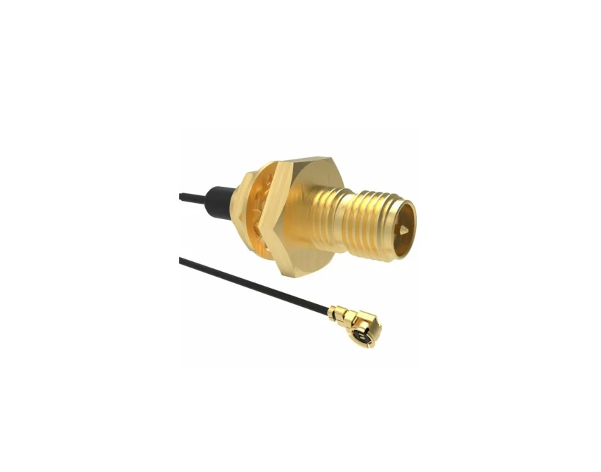
SMA adapter cable with miniature RF connector designed for connecting antennas, wireless modules, and compact electronic devices. Supports customized cable length and connector combinations.
An SMA connector cable is commonly used when equipment needs a compact, repeatable RF connection between modules, antennas, and test systems.
A typical assembly contains four basic elements:
- SMA connector interface
- Coaxial cable
- Cable termination process
- Electrical and mechanical inspection
The connector provides the mating interface. The coaxial cable controls signal transmission characteristics. The termination process determines whether the connection between the cable and connector remains stable during use.
A common mistake in sourcing is selecting the connector first and treating the cable as a secondary item. In RF applications, the rear section of the connector must match the cable diameter, dielectric structure, and termination method. An SMA connector designed for a larger cable cannot simply replace one designed for a smaller cable because the front interface looks identical.
Explain how SMA connector cables simplify RF integration
Instead of producing the cable termination process internally, many equipment manufacturers purchase finished cable assemblies with defined specifications:
- Fixed cable length
- Confirmed connector combination
- Known impedance
- Controlled termination quality
- Repeatable inspection results
This approach is especially useful for OEM products where hundreds or thousands of assemblies may be installed into the same design.
A production issue often starts with small differences. One batch may use a slightly different cable construction, another may have a different crimp condition, or the bending position may change after installation. These differences may not appear in a basic continuity check but can influence RF measurements.
For this reason, buyers usually need to specify more than just “SMA cable” in a purchase request.
Identify where pre-assembled SMA cables improve installation efficiency
SMA connector cables are used across many RF applications because they simplify mechanical integration.
Typical applications include:
| Application | Cable Requirement |
| RF Testing | Low loss and stable connection |
| Wireless Module | Compact cable size |
| Antenna System | Suitable frequency range |
| Communication Equipment | Reliable RF path |
| Laboratory Setup | Repeatable measurement connection |
In laboratory environments, SMA cable assemblies are often used as test connections between instruments and devices under test. Here, repeatability matters because a poor cable assembly can affect measurement results.
In wireless equipment, the priority may shift toward size and routing flexibility.
SMA Connector Cable Application Map
| Application | Main Concern | Selection Focus |
| RF Testing | Measurement repeatability | Stable loss and VSWR |
| Wireless Module | Limited installation space | Flexible cable diameter |
| Antenna System | Frequency matching | Cable and connector compatibility |
| Communication Device | Long-term stability | Mechanical reliability |
| Laboratory Setup | Accurate measurement | Tested cable assembly |
The same SMA connector cable may work well in one application and become unsuitable in another. A short jumper inside a test fixture has different requirements from a cable routed through an outdoor communication enclosure.
Before ordering, engineers should confirm the operating frequency, cable length, connector orientation, installation space, and required inspection standard.
That information provides the foundation for selecting an SMA connector cable assembly that matches the actual RF path instead of only matching the connector appearance.
How Do You Select the Right SMA Connector Cable for an RF Project?
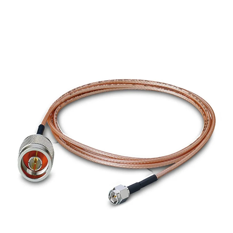
Many SMA cable problems start before production begins.
A drawing may only show “SMA to SMA cable, 500 mm” and the supplier receives no information about frequency, cable type, or test requirement. The first sample may arrive and fit the equipment correctly. Then the engineering team discovers a different problem: higher insertion loss than expected, unstable VSWR, or difficulty routing the cable inside the enclosure.
The connector interface is only one part of the assembly.
When preparing an SMA connector cable specification, engineers usually need to define several items together:
- SMA interface type and gender
- Cable model
- Cable length
- Operating frequency
- Impedance
- Connector angle
- Required inspection method
A complete specification reduces unnecessary substitutions during purchasing.
Match the cable specification with the actual RF path
A common mistake in RF sourcing is comparing cable assemblies only by connector appearance.
For example, two assemblies may both use SMA male connectors. One may use RG178 cable for a compact module, while another uses RG405 semi-rigid cable for a fixed microwave connection. The connectors look similar, but the cable behavior is different.
The cable affects:
- Attenuation over distance
- Mechanical flexibility
- Shielding effectiveness
- Installation stress
- Frequency capability
For short internal connections, flexibility may matter more than small loss differences. For test equipment or higher-frequency links, loss control usually becomes more important.
The specification should follow the application.
A short cable inside a GPS module and a 1-meter laboratory test cable are both SMA assemblies, but they should not be purchased with the same criteria.
Check cable diameter before confirming the assembly
Cable size is often ignored until installation starts.
A cable that works on the bench may become difficult to install after the enclosure, shielding parts, and nearby components are added.
Before ordering, check:
- Available routing space
- Minimum bending area
- Connector exit direction
- Cable fixing method
- Movement or vibration conditions
Small coaxial cables are easier to route, but the smaller structure also creates trade-offs.
One practical issue appears frequently during product updates. A prototype may use a short straight cable. Later, the production version requires a longer cable with a tighter bend. The original cable selection may no longer be suitable.
The cable should be selected according to the final assembly condition, not only the prototype.
Confirm SMA connector style before production release
SMA cable assemblies are available with different mechanical configurations.
Common choices include:
- SMA male to SMA male
- SMA male to SMA female
- Straight SMA connector
- Right-angle SMA connector
- Bulkhead SMA connector
Connector direction affects installation.
A right-angle connector can reduce stress when the cable exits close to a PCB edge. A straight connector may be better for test fixtures where repeated connection is required.
Polarity also needs confirmation.
Standard SMA and RP-SMA may look similar in product images, but they are different interfaces.
SMA Connector Cable Selection Checklist
| Item | Confirm Before Ordering |
| Interface | SMA / RP-SMA if required |
| Gender | Male or Female |
| Cable Model | RG178 / RG316 / RG405 or other |
| Impedance | Usually 50Ω for RF systems |
| Frequency | Maximum operating frequency |
| Length | Finished assembly length |
| Structure | Straight or right-angle |
| Test Requirement | VSWR / insertion loss if required |
This type of checklist is useful during RF purchasing because many cable problems are specification problems rather than manufacturing problems.
How Do RG178, RG316, and RG405 Change SMA Cable Selection?
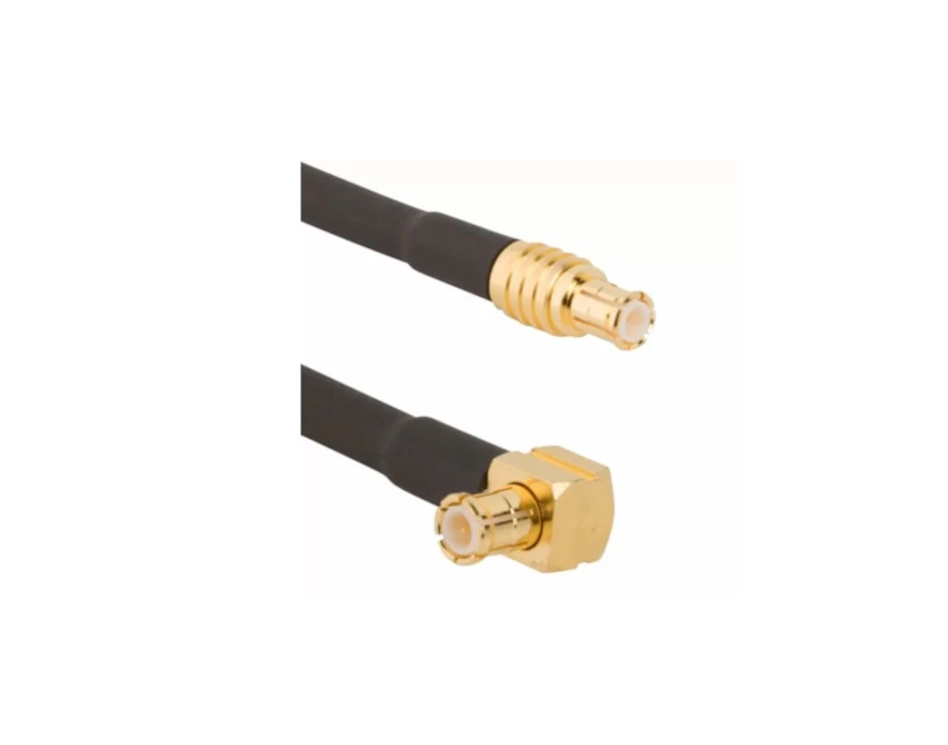
SMA right angle connector cable designed for space-limited RF installations. The angled connector helps reduce cable bending stress and provides flexible routing solutions for wireless devices and test equipment.
The coaxial cable inside the assembly often determines the practical limit of the SMA cable.
The SMA interface itself is standardized, but the cable connected behind it changes the final characteristics.
A buyer selecting an SMA connector cable should consider the cable family first, then match the connector structure.
When does RG178 make sense for an SMA cable assembly?
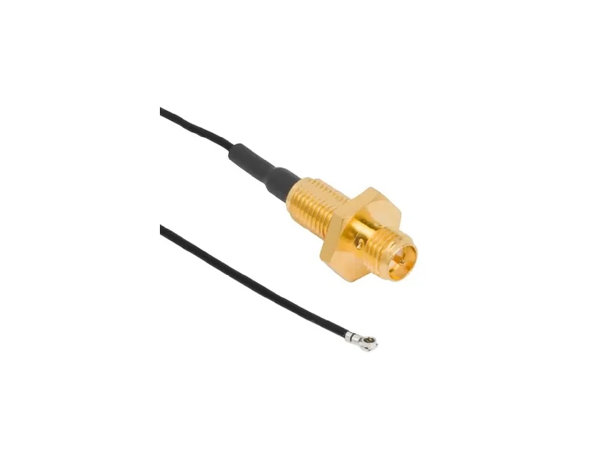
SMA bulkhead connector cable assembly featuring a panel mount SMA connector and miniature RF cable interface. Designed for antenna connections, wireless modules, and compact RF systems requiring stable signal transmission.
RG178 is commonly selected when the available installation space is limited.
Its small diameter makes it suitable for:
- Compact wireless devices
- Internal antenna connections
- Small electronic modules
The advantage is mechanical size.
However, smaller cable construction usually comes with higher attenuation compared with larger coaxial options. For short distances, this difference may be acceptable. For longer paths, the cable loss should be calculated before final approval.
RG178 is often a space-driven choice.
Why is RG316 widely used with SMA connectors?
RG316 is a common cable choice for general RF jumper assemblies.
However, “RG316” should not be treated as the only specification. Buyers should still confirm the exact construction, operating frequency, and inspection requirement.
Where does RG405 fit in SMA cable applications?
RG405 is a semi-rigid coaxial cable.
Unlike flexible cables, it keeps its formed shape after bending.
This makes it suitable for applications where the cable route is fixed, such as:
- Microwave assemblies
- RF modules with controlled routing
- Laboratory equipment
The limitation is obvious: it is not intended for frequent movement.
A semi-rigid cable installed in a moving assembly may experience mechanical stress at the connector transition point.
SMA Cable Material Comparison
| Cable Model | Structure | Suitable Situation |
| RG178 | Small flexible coax | Limited space and short connections |
| RG316 | Flexible coax | General SMA jumper assemblies |
| RG405 | Semi-rigid coax | Fixed high-frequency RF paths |
There is no single SMA cable option that fits every project.
A measurement system may prioritize loss stability. A fixed microwave assembly may require mechanical consistency.
The cable model should be written into the BOM together with the SMA connector specification. This simple step helps avoid receiving a mechanically compatible cable that does not match the intended RF application.
How Do SMA Connector Choices Affect RF Signal Quality?
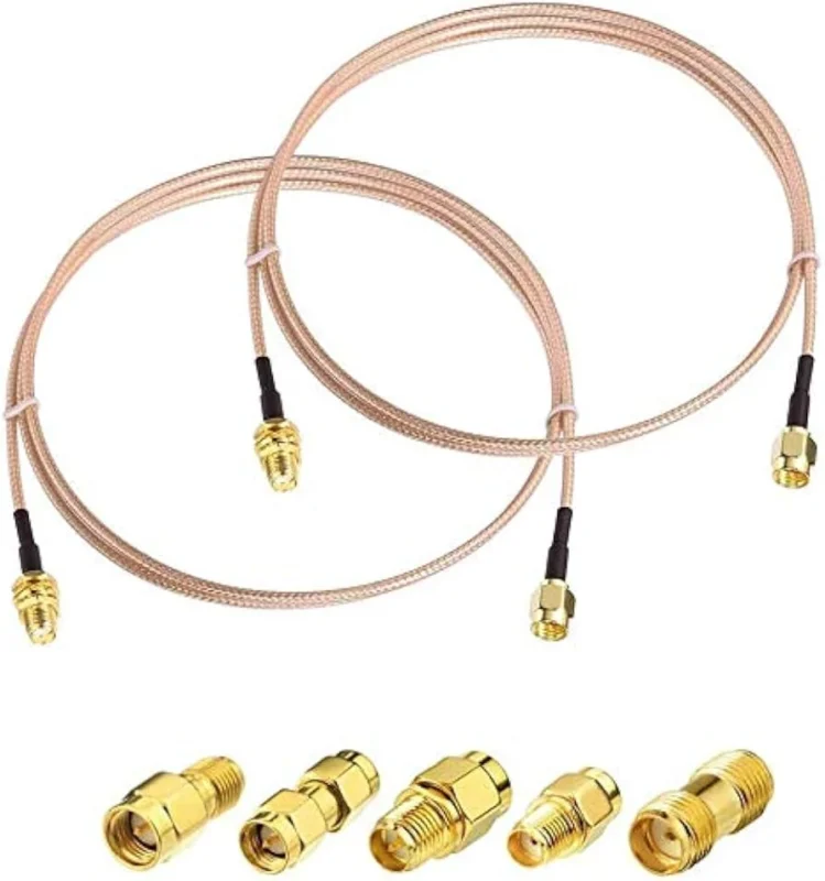
A connector that fits mechanically is not always the connector that performs correctly in an RF system.
This situation appears frequently during sample approval. The cable can be assembled, the SMA thread can tighten normally, and the equipment may even show a signal. The problem is found later during RF measurement when the VSWR value is different from the expected result.
The reason is that an SMA connector is part of the electrical path.
The internal structure of the connector, the contact position, the transition between cable and connector, and the termination process all influence the final assembly.
When reviewing an SMA connector cable, engineers usually check:
- Connector interface
- Frequency range
- Impedance
- Termination method
- Cable compatibility
- Test requirement
A connector should be evaluated together with the cable it is installed on.
Why can two SMA cable assemblies with the same connector look different in testing?
The outside appearance often creates confusion.
Two SMA male cable assemblies may look identical in a purchasing photo. One may use RG316 flexible coax, while another may use a different cable with another dielectric structure and attenuation value.
The connector head is only the visible part.
Inside the assembly, differences may exist in:
- Center pin positioning
- Dielectric support
- Shield connection
- Crimp quality
- Soldering condition
At lower frequencies, some differences may not create obvious problems. Near the upper operating range, small mechanical changes can affect RF measurements.
This is why production buyers should avoid replacing cable assemblies only based on connector appearance.
How Does SMA Cable Length Change Signal Loss?
Cable length is often decided by mechanical installation first.
An engineer may need a 300 mm cable instead of 150 mm because the antenna position changes or the PCB layout is updated. However, the additional length also changes the RF path.
The longer the coaxial cable becomes, the more attention should be paid to attenuation.
The actual loss depends on:
- Cable model
- Operating frequency
- Cable construction
- Connector quantity
A short RG178 cable inside a compact module and a longer RG405 cable in a test fixture should not be compared using the same expectation.
What should engineers check when the SMA cable becomes longer?
When cable length increases, several options can be considered:
| Situation | Possible Action |
| Long cable route | Select lower attenuation cable |
| High-frequency signal | Review cable specification |
| Multiple adapters | Reduce unnecessary connections |
| Test application | Confirm measurement requirement |
Adapter quantity is another detail that is easy to miss.
A single adapter may not create a noticeable issue. A chain of adapters combined with a longer cable can introduce additional loss and reflection.
For laboratory connections, keeping the RF path simple often improves measurement consistency.
SMA Cable Loss Calculation Reference
| Item | Information Needed |
| Cable Type | RG178 / RG316 / RG405 |
| Frequency | Operating GHz |
| Length | Finished cable length |
| Attenuation | dB/m |
| Connector Number | Quantity of interfaces |
| Target Loss | Acceptable dB value |
This information can also be included in an RF purchasing document to help suppliers select a suitable cable structure.
How Should Custom SMA Connector Cables Be Specified Before Ordering?
Custom cable assemblies usually fail because the requirement is incomplete, not because the supplier cannot manufacture them.
A request saying:
“SMA cable, 1 meter”
leaves many unanswered questions.
The supplier still needs to know:
- Which SMA interface?
- Male or female?
- Which cable?
- Straight or right-angle?
- Required frequency?
- Is testing required?
A clearer RF request might look like:
SMA male to SMA female cable assembly, RG316, 500 mm, 50Ω, operating frequency requirement, VSWR inspection required.
That information gives both sides a common reference.
What information should be included in an SMA cable RFQ?
Custom SMA Connector Cable RFQ Template
| Field | Example |
| Assembly Type | SMA Connector Cable |
| Connector A | SMA Male |
| Connector B | SMA Female |
| Cable Model | RG316 |
| Impedance | 50Ω |
| Length | Custom |
| Frequency | Required operating range |
| Test | VSWR / Insertion Loss |
For special assemblies, drawings are recommended.
This is especially true for:
- Right-angle cable routing
- Panel mounting cables
- Fixed bending positions
- Space-limited equipment
A drawing prevents misunderstandings that are difficult to describe through text alone.
How Should SMA Connector Cables Be Checked Before Delivery?
The final inspection depends on where the cable will be used.
A laboratory test cable may require tighter RF verification than a short internal connection cable.
Common checks include:
Electrical inspection
- Continuity
- VSWR
- Return loss
- Insertion loss
Mechanical inspection
- Connector installation
- Cable length
- Appearance
- Pull condition
- Bend area
A visual inspection can confirm whether the connector is damaged or incorrectly installed. It cannot confirm the complete RF performance.
If a future batch shows a change, engineers can compare against the original reference instead of starting from zero.
SMA Connector Cable Acceptance Checklist
| Inspection Item | Check Point |
| Connector Type | Matches drawing |
| Cable Model | Confirmed |
| Length | Within tolerance |
| Impedance | Required value |
| Frequency Range | Suitable |
| VSWR | Tested when required |
| Insertion Loss | Measured when required |
| Appearance | No damage |
FAQ
Can RG178, RG316, and RG405 use the same SMA connector?
Not always. The SMA interface may be the same, but the connector rear structure and termination method need to match the cable diameter and construction.
Does an SMA connector with a higher frequency rating always provide better results?
No. The complete cable assembly depends on the connector, cable, length, and termination quality together.
Why does an SMA cable pass a basic electrical test but fail RF testing?
Continuity only confirms the connection path. RF tests evaluate additional factors such as reflection and insertion loss.
Can SMA connector cables be made with custom lengths and connector combinations?
Yes. Custom assemblies can usually include different SMA interfaces, cable lengths, cable types, connector angles, and inspection requirements.
A good SMA connector cable specification starts with the complete RF path. The connector name alone is not enough. Defining the cable model, operating frequency, installation condition, and test requirement before ordering helps avoid changes after production begins.