
A connector mismatch often looks like a small mechanical problem.
An SMA male port does not mate with another SMA male port. A test cable uses the correct frequency range, but the equipment interface is different. A new RF module passes incoming inspection, yet the engineer cannot connect it to the existing measurement setup.
The first solution many teams consider is replacing the cable assembly. That may work, but it is not always the most practical option.
In many RF systems, the better approach is adding the correct SMA adapter between existing interfaces. The adapter changes the mechanical connection while maintaining the required RF path characteristics. The challenge is that not every adapter that physically fits is suitable for the application.
A laboratory connection at 2 GHz, a VNA test setup at 26.5 GHz, and an outdoor antenna system may all use SMA interfaces, but the selection requirements are different.
The adapter body, gender, impedance, frequency rating, VSWR, and mating structure all need to match the actual RF path.
How Do SMA Adapters Solve RF Interface Conversion Problems?
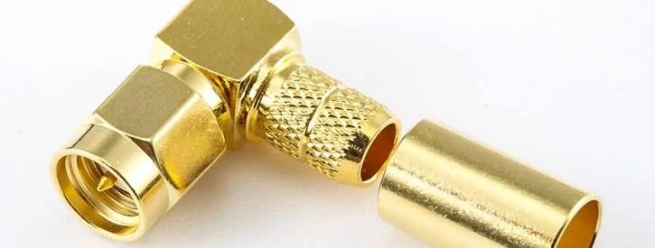
This right angle SMA RF adapter provides a practical solution for changing connector orientation and improving installation flexibility. Proper selection of adapter type, impedance, and frequency range helps maintain reliable RF performance.
A common sourcing mistake is treating an RF adapter as only a mechanical accessory.
The thread size may match. The connector may lock correctly. A continuity test may even pass.
However, RF systems operate differently from low-frequency electrical connections.
A VNA test cable, for example, may already be calibrated and qualified. Replacing the complete cable because the equipment port is incompatible creates unnecessary cost and may introduce additional variables.
Understand the difference between adapters and connectors
The terms SMA connector and SMA adapter are sometimes mixed during purchasing.
They serve different purposes.
A connector is normally terminated onto a cable, PCB, or equipment interface. An adapter connects two existing connector interfaces.
| Component | Main Function | Typical Use |
| SMA Connector | Terminates cable or device interface | SMA cable assembly, PCB connector |
| SMA Adapter | Connects two existing interfaces | Port conversion, test connection |
| RF Adapter | Converts different RF connector standards | SMA to BNC, SMA to N |
| Adapter Cable | Combines cable and interface conversion | Flexible equipment connection |
For example, an SMA male connector installed on an RG316 cable is not interchangeable with an SMA male-to-male adapter.
The first component creates an RF termination. The second joins two existing ports.
This difference matters during BOM preparation. A purchase request stating only “SMA connector” may result in receiving a cable termination part instead of the required interface converter.
Compare SMA adapters with general coax adapters
The term coax adapter is broader than SMA adapter.
A coaxial adapter may include many connector families, such as BNC, N-Type, TNC, MMCX, MCX, and SMA. An SMA adapter specifically focuses on SMA interfaces or SMA-based transitions.
The selection should start from the actual interface requirement.
A few common examples:
| Adapter Category | Main Purpose | Typical Application |
| SMA Adapter | SMA interface conversion | RF modules, test equipment |
| Coax Adapter | General coaxial interface conversion | Cable systems |
| RF Adapter | RF connector transition | Communication equipment |
| Microwave Adapter | High-frequency interface transition | Precision test systems |
A buyer working on a wireless module may need an SMA female-to-female adapter because two SMA male cables must be connected.
A test engineer working with laboratory equipment may require an SMA to BNC adapter because the instrument interface is different.
The connector name alone does not define the correct solution. The complete RF path must be considered.
How Do SMA Adapter Gender Configurations Affect Compatibility?
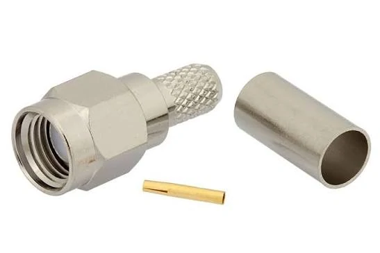
This image shows the basic structure of an SMA adapter, including the connector body, sleeve, and center contact. Understanding the internal construction of an SMA adapter helps engineers select suitable RF interface conversion components for test equipment, communication systems, and antenna applications.
Many SMA adapter selection problems come from one simple detail: gender.
SMA interfaces use male and female configurations, but the correct combination depends on the ports being connected.
A wrong gender selection may look obvious after delivery, but it is a common issue in RF purchasing because product images often appear similar.
Before ordering, confirm:
- Connector gender
- Interface standard
- Thread configuration
- Impedance
- Frequency requirement
A correct adapter should solve the connection problem without forcing mechanical stress on either port.
Select SMA female to female adapters for connecting two SMA male ports
An SMA female to female adapter is commonly used when both sides of the existing cables or equipment ports are SMA male. A low-frequency adapter used near its upper limit may introduce higher VSWR or unstable measurement results.
Match SMA male to female adapters correctly
An SMA male to female adapter changes the interface direction between two connector genders.
This type is useful when equipment interfaces have different mating requirements.
For example:
- SMA male equipment port → SMA female cable
- SMA female equipment port → SMA male cable
The mechanical conversion is simple, but engineers should still verify whether the adapter changes the physical orientation, mounting clearance, or cable routing.
In compact RF assemblies, a straight adapter and a right-angle adapter may produce very different installation results.
SMA Adapter Gender Selection Table
| Adapter Type | Connection Purpose | Common Application |
| SMA Female to Female | Connect two SMA male interfaces | RF cable extension, laboratory setup |
| SMA Male to Male | Connect two SMA female interfaces | Equipment port connection |
| SMA Male to Female | Change interface direction | System integration |
| Custom SMA Adapter | Special interface requirement | OEM equipment |
A practical purchasing rule is:
Identify the two existing ports first, then select the adapter. Do not select the adapter first and try to match the equipment afterward.
This avoids a common production problem: receiving the correct connector family but the wrong interface combination.
How Do You Select the Right SMA Adapter for RF Equipment?
A common purchasing mistake happens before the quotation stage: selecting an SMA adapter by appearance.
Two adapters may look almost identical in a product photo. Both may have SMA threads, similar dimensions, and the same gold-plated contact appearance. However, the internal structure, impedance control, and frequency capability may be different.
For RF systems, mechanical compatibility is only the first filter.
A suitable SMA adapter should match:
- Interface type
- Connector gender
- Impedance
- Frequency range
- VSWR requirement
- Installation environment
- Mating frequency
A development engineer may accept a simple adapter for a low-frequency prototype. A production test system running close to the upper frequency limit requires much tighter control.
The adapter becomes part of the RF transmission line. Every additional interface creates another possible point of mismatch.
Check connector gender before installation
Before ordering an SMA adapter, confirm the two ports that need to be connected.
A simple RF adapter request should include:
- Port A type
- Port B type
- Male or female interface
- Straight or right-angle structure
- Panel mount or cable connection requirement
The second description gives the supplier enough information to evaluate the RF path.
This is especially important for OEM projects where the adapter becomes part of a larger assembly. A small interface mistake can affect cable routing, enclosure design, and production installation.
Match impedance and frequency requirements
Most SMA RF adapters are designed for 50Ω systems, which matches common RF test equipment, communication modules, and antenna systems.
However, impedance should not be assumed only from the connector shape.
The complete RF chain should be considered:
- Equipment port impedance
- Cable impedance
- Adapter impedance
- Antenna interface requirement
A 50Ω SMA adapter connected into a mismatched system can still create reflection problems.
Frequency rating is another key factor.
An adapter marked for DC–6GHz may be acceptable for many general RF applications. The same adapter may not be suitable for a 26.5GHz measurement setup.
The frequency rating should provide enough margin above the actual operating frequency.
A practical engineering reference:
Frequency Margin Ratio = Adapter Rated Frequency ÷ Maximum Operating Frequency
| Frequency Margin Ratio | Application Recommendation |
| ≥1.2× | General RF connection |
| ≥1.5× | Test cables and measurement setups |
| ≥2.0× | Sensitive RF measurement or low-VSWR applications |
This ratio is not a replacement for actual testing, but it helps avoid selecting an adapter that operates too close to its limit.
Avoid selecting adapters only by mechanical fit
A connector that screws together does not automatically create a good RF connection.
Several issues may appear after installation:
- Increased VSWR
- Higher insertion loss
- Unstable measurement results
- Intermittent contact after repeated mating
One common field situation is a prototype that works during initial testing but shows inconsistent results during production.
The reason is often not the equipment itself. The production version may use:
- Longer cable routing
- More adapter connections
- Different tightening conditions
- Different cable bending positions
The adapter selection should consider the final assembly condition, not only the first sample.
SMA Adapter Selection Checklist
| Parameter | Requirement |
| Interface | SMA standard |
| Gender | Male / Female confirmed |
| Impedance | 50Ω |
| Frequency | Above operating frequency |
| VSWR | Match application requirement |
| Mounting | Straight / Right angle |
| Application | Test equipment / Antenna / Module |
For procurement teams, this checklist can be added directly to an RF purchase request.
It reduces repeated communication because the supplier receives the information needed for technical evaluation.
How Do SMA to BNC and SMA to N Adapters Extend RF Compatibility?
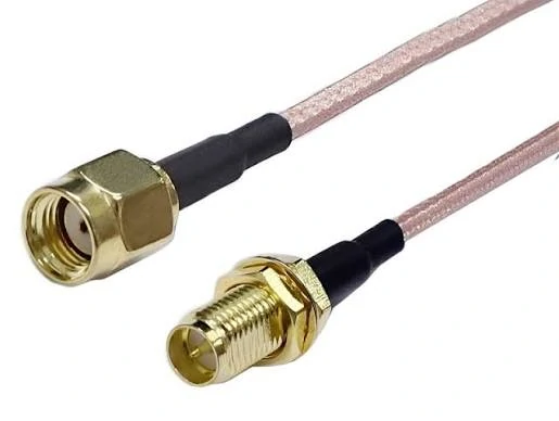
This SMA adapter cable assembly demonstrates a flexible RF connection solution. By combining coaxial cable with SMA connectors, it supports applications where direct connector mating is not possible due to interface differences or installation limitations.
RF equipment rarely uses only one connector family.
Replacing all equipment cables to match one connector standard is usually unnecessary.
Interface conversion adapters provide a practical solution.
Select conversion adapters based on frequency requirements
Interface conversion becomes more challenging as frequency increases.
Important parameters include:
- Frequency range
- VSWR
- Return loss
- Insertion loss
- Connector alignment
For example:
A DC–6GHz adapter may be suitable for general communication testing.
A DC–26.5GHz adapter may be required for microwave measurement systems.
The connector interface alone does not determine the final RF performance. Cable type, adapter quantity, and assembly method also influence the result.
Interface Conversion Matrix
| Adapter Type | Connects | Typical Application |
| SMA to BNC | SMA ↔ BNC | Laboratory testing |
| SMA to N | SMA ↔ N-Type | Antenna systems |
| SMA to SMA | SMA ↔ SMA | RF extension |
| SMA to Other RF | Custom interface conversion | Special equipment |
A useful engineering rule is:
The more interfaces added into an RF path, the more attention should be paid to total insertion loss and mismatch.
An adapter may solve a mechanical problem, but the final RF system still needs verification.
Select SMA adapters according to operating frequency
Typical SMA adapter application ranges include:
| Application Area | Example Frequency Requirement | Selection Focus |
| General RF connection | DC–6GHz | Mechanical compatibility and impedance |
| Wireless testing | DC–18GHz | VSWR and repeatability |
| Microwave measurement | DC–26.5GHz | Precision interface control |
The cable assembly connected to the adapter should also be considered.
A high-frequency adapter cannot compensate for a cable that has excessive loss or an unsuitable connector termination.
Consider VSWR and insertion loss in high-frequency systems
At higher frequencies, small mechanical differences become more significant.
Factors affecting RF performance include:
- Center contact alignment
- Dielectric structure
- Contact surface condition
- Manufacturing tolerance
- Mating condition
Important test parameters:
- VSWR
- Return Loss
- Insertion Loss
For production applications, random sampling may be used to confirm consistency.
For precision measurement systems, suppliers may need to provide additional test data or verification records.
How Are SMA Adapters Used in RF Testing and Antenna Applications?
This image shows a right angle SMA adapter designed for space-saving RF installation. It is commonly applied in wireless devices, RF modules, and test systems where connector orientation and mounting clearance are important considerations.
Many SMA adapter requirements appear after equipment selection has already started.
A test cable may already be installed. The RF instrument may have a fixed interface. A new module or antenna component arrives with a different connector.
This situation is common in prototype projects.
Changing the complete cable assembly is not always the best choice. In some cases, the existing cable has already been verified with the test system. Replacing it means repeating cable evaluation and adjusting the fixture again.
An SMA adapter provides another option.
The adapter creates the mechanical connection between two interfaces, but its influence is not limited to the outside dimensions. Once installed, it becomes part of the RF path.
For applications above several GHz, the adapter structure, contact alignment, and manufacturing consistency may affect the final measurement.
Connect SMA adapters with test instruments
RF laboratories often contain equipment from different manufacturers.
One device may use SMA. Another may use BNC. A test fixture may use N-Type.
This does not mean the entire cable system needs to be changed.
An SMA adapter can be used to connect existing equipment while keeping the original cable configuration.
A typical example is a VNA test environment.
The cable has already been matched with the measurement system. During a new project, the device under test uses a different interface. Adding an adapter is usually easier than rebuilding the complete connection.
For repeated testing, the adapter should be treated as a controlled component.
The issues that usually appear in production are not always obvious during the first sample:
- The connector becomes loose after repeated mating
- Different batches show slightly different mechanical tolerance
- Test results change after replacing the adapter
This is why suppliers and buyers often confirm connector structure, frequency range, and inspection requirements before using adapters in a fixture.
Support antenna and wireless equipment connections
SMA connectors are widely used in compact RF products because they provide a practical balance between size and connection stability.
They are commonly found in:
- Wireless modules
- RF evaluation boards
- Antenna test equipment
- Communication devices
During integration, different parts of the system may use different connector families.
For example, the internal module may use SMA while the external antenna cable uses N-Type.
An SMA to N adapter can solve this interface difference.
The selection depends on more than the connector name.
An indoor test setup and an outdoor antenna installation have different requirements.
Outdoor applications may involve:
- Cable weight
- Installation stress
- Weather exposure
- Long-term maintenance
A small adapter installed between a heavy antenna cable and a device port may experience mechanical pressure that does not exist on a laboratory bench.
Improve flexibility in RF system design
Adapters are especially useful during development because hardware designs often change.
A prototype may use an SMA interface because it is convenient for testing.
A production cable with fewer connection points is easier to inspect and easier to maintain.
How Should SMA Adapters Be Tested Before RF Deployment?
An SMA adapter can look correct and still create problems in an RF system.
Visual inspection can confirm the external condition, but it cannot show internal electrical behavior.
During incoming inspection, suppliers usually check the basic mechanical condition first:
- Correct connector type
- Correct gender
- Thread condition
- Center contact appearance
- Housing damage
The adapter should mate naturally with the matching connector.
If installation requires abnormal force, tightening harder is not the answer. The issue may come from incorrect matching or mechanical damage.
Verify RF electrical performance
A continuity test is useful because it is quick.
It confirms that the electrical path is connected.
But RF systems require additional evaluation.
For higher-frequency applications, buyers may request:
| Test Item | Check Purpose |
| VSWR | Confirm impedance matching |
| Return Loss | Check reflected signal |
| Insertion Loss | Evaluate transmission loss |
The reason is simple: an RF connection can be electrically connected but still perform poorly at operating frequency.
For applications such as VNA testing, microwave measurement, or production verification, RF testing provides a clearer picture than appearance inspection alone.
SMA Adapter Acceptance Checklist
| Inspection Item | Requirement |
| Adapter Type | Correct SMA model |
| Gender | Confirmed |
| Impedance | 50Ω |
| Frequency | Suitable for application |
| Thread Quality | Pass |
| Contact Condition | Stable |
| VSWR | Tested when required |
| Appearance | No damage |
How Should Engineers Specify SMA Adapters for Custom RF Projects?
Many quotation delays come from incomplete descriptions.
does not define the actual product.
The supplier still needs to know the connection requirement.
FAQ
Why does my SMA adapter connect correctly but the RF test result is unstable?
A mechanical connection only confirms that two connectors can mate. It does not show whether the RF path is working correctly. In some cases, an adapter may pass basic inspection but show different results after installation because of contact alignment, frequency limitation, or additional mismatch in the connection chain. For sensitive measurements, the adapter should be checked together with the cable and test equipment.
Why can the SMA adapter fit the port but still cause unstable testing?
A connector that can be screwed together is not always a good RF connection. Problems may appear after the adapter is installed in the actual setup, especially when the cable length, test fixture, or operating frequency changes. In this case, check the adapter together with the complete RF path instead of checking the adapter alone.
I have two SMA male cables. What adapter should I order?
For two SMA male cables, the usual choice is an SMA female to female adapter. This allows both male connectors to mate correctly. Before placing an order, confirm the connector standard and frequency range because two adapters with the same appearance may not have the same RF characteristics.
Is a 6GHz SMA adapter enough for a higher frequency system?
It depends on the actual working frequency. A 6GHz adapter may be suitable for general RF connections, but it is not normally selected for a system operating close to or above that range. For microwave applications, leave enough frequency margin and check the complete connection, including the cable and other RF components.
What should I tell a supplier when requesting an SMA adapter?
A product name alone is usually not enough. Provide the two connector interfaces, male or female type, impedance, operating frequency, application, and quantity. If the adapter will be used in equipment or a test fixture, also mention mounting space, cable type, or any inspection requirements.
