
A cable can fit mechanically and still fail electrically.
This is a common issue during RF system integration. An engineer may select an adapter because the connector threads match, the cable can be tightened, and the first bench test shows signal output. The problem appears later when the system operates near the upper frequency limit, the cable is routed differently, or several adapters are connected together. A small mismatch that was invisible at low frequency can become noticeable through higher VSWR, additional insertion loss, or unstable measurement results.
A coax adapter is often used to solve interface differences between RF components, but selecting one requires more than checking whether two connectors can physically mate. Connector standard, impedance, frequency capability, gender, mounting style, and application environment all affect whether the adapter is suitable for the complete RF path.
A microwave measurement system working above several GHz may need a precision adapter designed for higher-frequency operation instead of a general-purpose connector transition.
How Does a Coax Adapter Connect Different RF Interfaces?
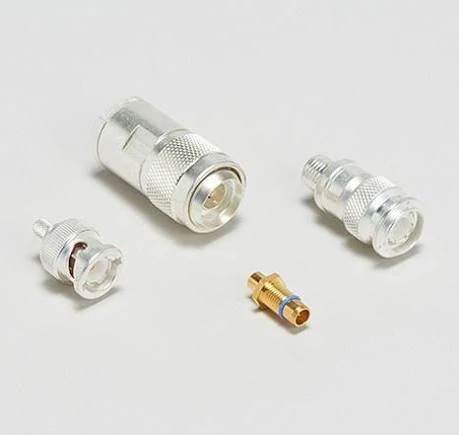
Assorted RF coax adapters and connectors used to create transitions between different coaxial interfaces in RF testing, communication equipment, and antenna systems.
RF equipment rarely uses only one connector standard. Development laboratories, communication systems, antenna assemblies, and production test stations often contain equipment from different generations. One instrument may use BNC, a compact RF module may use SMA, an antenna feeder may use N Type, while older radio equipment may still use UHF or F connectors.
A coax adapter provides a direct mechanical and electrical transition between these interfaces.
Typical applications include:
- connecting test equipment with different connector standards
- adapting RF cables during prototype development
- replacing discontinued interface combinations
- connecting antennas with different feed interfaces
- building temporary measurement configurations
The important point is that an adapter does not simply “change the connector shape”. It becomes part of the RF transmission path.
A complete RF connection should be considered as:
Equipment → Adapter → Cable → Connector → Antenna/Load
Any change inside this chain can influence signal behavior.
A suitable coax adapter needs to match several factors:
| Selection Factor | Why It Matters |
| Connector interface | Determines whether two devices can physically connect |
| Gender | Prevents incorrect male/female mating selection |
| Impedance | Maintains system matching, normally 50Ω for RF systems |
| Frequency range | Ensures the adapter works within the operating band |
| Mounting style | Determines suitability for cable, panel, or fixture installation |
| Application environment | Affects vibration, weather exposure, and repeated mating |
A frequent sourcing mistake is selecting only by connector name. For example, an SMA adapter may describe many different products, including SMA male-to-female, SMA female-to-female, SMA bulkhead versions, and high-frequency precision models. They are not interchangeable simply because the front interface looks similar.
How Do You Check Mechanical and Electrical Compatibility Before Ordering?
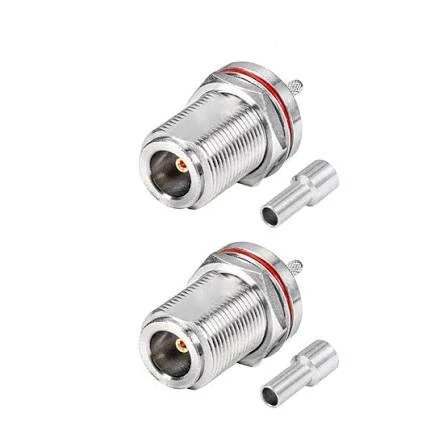
N Type female bulkhead RF coax connectors with mounting hardware and cable ferrules, suitable for panel installations, antenna systems, and communication equipment.
The connector interface is the first step, not the final decision.
Before purchasing a coax adapter, engineers usually confirm five basic items:
Confirm the connector standard
Different RF connectors have different mechanical designs.
Common examples include:
- SMA adapter for compact RF modules and test connections
- BNC adapter for quick-connect laboratory equipment
- N Type adapter for antenna and communication systems
- TNC adapter for applications requiring threaded coupling
- F connector adapter for TV and video coax systems
- UHF adapter for radio applications
The external appearance can sometimes be misleading.
Verify impedance matching
Some video and broadcast applications use 75Ω systems.
A 50Ω coax adapter and a 75Ω adapter may look similar externally, but they are designed for different transmission systems.
Connecting mismatched impedance components may create:
- signal reflection
- increased VSWR
- measurement uncertainty
- additional insertion loss
The adapter should match the surrounding RF chain:
Connector + Adapter + Cable + Equipment
not just the connector at one end.
Check frequency capability
Frequency rating is another area where buyers often underestimate the difference.
A coax adapter that works well at lower frequencies may not provide the same results at higher bands.
For example:
| Application | Typical Connector Choice | Main Consideration |
| Wireless module testing | SMA adapter | Compact size and RF accuracy |
| General laboratory equipment | BNC adapter | Easy connection and frequent mating |
| Outdoor antenna system | N Type adapter | Mechanical strength and environment |
| Microwave measurement | 2.92mm / 3.5mm adapter | Higher frequency accuracy |
The highest operating frequency of the system should be considered before selecting the adapter. The connector rating alone does not guarantee the complete assembly performance because cable type, adapter quantity, and termination quality also influence RF behavior.
Coax Adapter Quick Selection Matrix
Use this matrix during early RF component selection:
| Application Requirement | Recommended Adapter Direction | Check Before Purchase |
| RF module connection | SMA adapter | Size, 50Ω impedance, frequency range |
| Laboratory measurement | BNC adapter | Connector gender, test frequency |
| Antenna feed system | N Type adapter | Outdoor rating, cable compatibility |
| Vibration environment | TNC adapter | Thread locking structure |
| Radio equipment | UHF adapter | Interface standard confirmation |
| Video/coax system | F connector adapter | 75Ω matching |
This simple check prevents many common ordering errors. A connector that fits physically is only the starting point. The final selection depends on whether the adapter can maintain the expected RF behavior after installation.
For engineers and procurement teams, the adapter specification should always include the interface combination, gender, impedance, frequency range, cable type, and intended application. This information is usually more valuable than a product photo when communicating with a supplier.
How Do SMA, BNC, N Type, and TNC Adapters Behave in Different RF Systems?
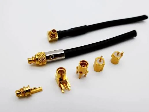
A selection of compact RF coax connectors and antenna assemblies illustrating different miniature interface and mounting structures used in wireless and RF applications.
A coax adapter is usually purchased when two existing RF components do not share the same connector interface.
The request often looks simple:
“Need SMA to BNC.”
“Need N to SMA.”
“Need a TNC adapter for this antenna.”
However, the connector name alone does not tell the full story.
During actual sourcing, engineers usually discover additional questions:
- Is the system 50Ω or 75Ω?
- Is this connection temporary for testing or part of the final product?
- Will the adapter be installed indoors or exposed to vibration and weather?
- Does the frequency requirement stop at a few GHz, or does it approach microwave range?
A coax adapter works inside the entire RF path. The connector interface is only the visible part.
Which Connector Characteristics Should Be Considered Before Selecting a Coax Adapter?
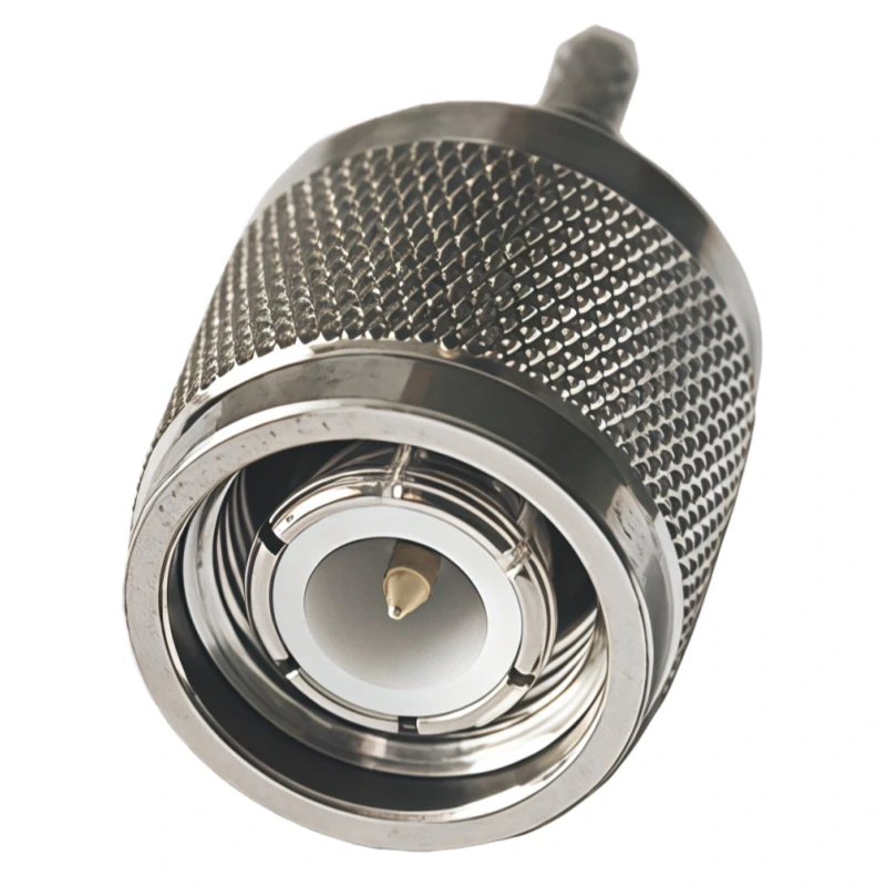
Close-up view of an N Type male RF coax connector showing the center contact, dielectric structure, threaded coupling area, and knurled outer body.
Different connector families developed around different application requirements.
Some focus on compact size. Some focus on mechanical strength. Others are designed around frequent laboratory connection.
Choosing an adapter based only on physical appearance can create problems later.
For example, a small SMA adapter may be convenient inside a test fixture, but it may not be the right choice for an outdoor antenna connection where mechanical stress is higher.
When Is an SMA Adapter a Better Choice Than Other RF Interfaces?
Instead of replacing the complete cable assembly, an adapter provides a quick connection method.
But SMA selection still requires attention.
Two SMA adapters may look almost identical while having different specifications:
- standard SMA or reverse polarity structure
- cable mount or bulkhead type
- general-purpose or precision machining
- different frequency capability
At higher frequencies, the internal geometry becomes more sensitive. The center contact alignment and dielectric structure influence the electrical result.
A connector that works well at a lower frequency does not automatically provide the same performance near the upper limit.
Why Are BNC Adapters Still Common in RF Testing?
Typical examples:
- oscilloscopes
- signal generators
- laboratory instruments
- educational test platforms
- general electronic measurement systems
A BNC adapter is often used when engineers need to connect modern RF equipment with older test equipment.
One common combination is:
BNC interface equipment + SMA cable assembly
The adapter solves the mechanical difference, but impedance should still be checked.
BNC connectors are available in both 50Ω and 75Ω versions.
This difference matters.
A connection may pass a basic continuity test, and the operator may be able to tighten the connector normally.
Where Does an N Type Adapter Fit Better Than SMA or BNC?
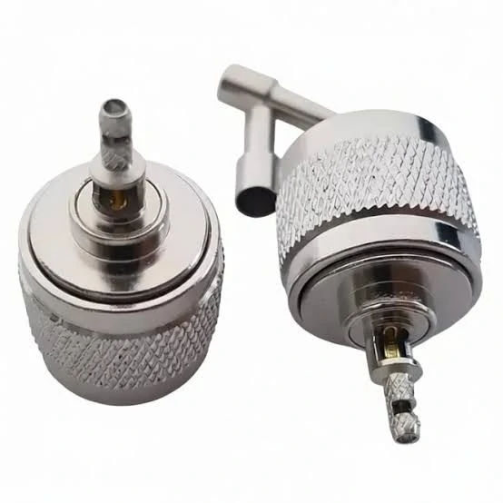
Rear and side views of N Type RF coax connectors showing the cable termination and coupling structure used in antenna, wireless communication, and coaxial cable systems.
Compared with SMA and BNC, N Type connectors have a larger structure and are commonly used in systems where cable size and environmental conditions become more important.
Typical applications include:
- antenna feeder systems
- wireless communication equipment
- outdoor RF installations
- base station related connections
An outdoor antenna system is a good example.
The adapter may stay installed for months or years. It may experience temperature changes, vibration, moisture, and repeated maintenance.
In this situation, the selection focus changes.
The engineer may pay more attention to:
- connector sealing structure
- cable compatibility
- mechanical strength
- installation method
- long-term contact stability
A small laboratory adapter may perform well electrically but may not be the practical choice for a fixed outdoor installation.
Why Do Some Applications Prefer TNC Adapters?
The adapter still needs to match:
- impedance
- frequency range
- cable type
- mating connector
Mechanical stability and RF performance are separate requirements.
How Should Engineers Compare Different Coax Adapter Options?
A practical comparison is usually based on the working environment.
| Adapter Type | Common Working Area | Main Reason for Selection | Possible Concern |
| SMA Adapter | RF modules and test systems | Compact size and precision connection | Interface and frequency mismatch |
| BNC Adapter | Laboratory equipment | Fast connection and easy operation | 50Ω/75Ω confusion |
| N Type Adapter | Antenna and communication systems | Mechanical strength | Size and installation space |
| TNC Adapter | Mobile or vibration environments | Threaded locking | Limited availability compared with common types |
The “best” adapter depends on the system requirement.
A laboratory engineer may prefer a compact SMA transition because it can be changed quickly.
A field installation engineer may prefer N Type because the connection needs to survive outside conditions.
Neither choice is universally better.
What Happens When Multiple Coax Adapters Are Used Together?
Adapter stacking is another area that is often overlooked.
During prototype testing, engineers may connect:
Instrument → Adapter → Cable → Adapter → Device
This approach is acceptable when flexibility is more valuable than minimizing connection points.
The risk increases when several adapters remain in a permanent RF path.
Each additional interface introduces:
- another contact point
- another mechanical tolerance
- another possible reflection location
At lower frequencies, the effect may be small.
At higher frequencies, the accumulated influence becomes easier to measure.
For critical RF testing, engineers usually verify the completed path using:
- VNA measurement
- VSWR check
- insertion loss measurement
- return loss evaluation
A continuity test only confirms that the circuit is connected. It does not confirm that the RF path performs correctly.
Coax Adapter Selection Notes for RF Buyers
When requesting a quotation, a clear specification saves time for both the buyer and supplier.
Instead of:
“Need SMA adapter.”
A better request includes:
- connector A
- connector B
- male/female combination
- impedance
- frequency range
- application
- quantity
- mounting requirement
Example:
50Ω SMA female to BNC male coax adapter, DC–6 GHz, used for RF laboratory testing equipment.
This information reduces incorrect substitutions and helps confirm whether the selected adapter is suitable before production or installation.
How Do You Specify, Test, and Purchase the Right Coax Adapter?
A coax adapter problem usually appears before anyone notices the adapter itself.
The cable does not fit the equipment during installation.
The measured VSWR is higher than expected.
The production team discovers that the purchased adapter uses a different mounting style.
These situations are not always caused by poor product quality. In many cases, the original requirement was incomplete.
For RF components, a purchase request should describe the electrical and mechanical conditions together. A connector drawing or product photo is useful, but it is rarely enough for a complete evaluation.
What Specifications Should Be Confirmed Before Ordering a Coax Adapter?
A supplier needs more than the words “SMA adapter” or “N adapter” to identify the correct product.
A complete requirement normally includes:
- connector interface A
- connector interface B
- male/female configuration
- impedance
- frequency range
- mounting style
- application environment
- quantity requirement
For example:
A buyer requesting:
SMA to BNC adapter
could mean several different products:
- SMA male to BNC female
- SMA female to BNC male
- SMA bulkhead to BNC cable adapter
- high-frequency SMA to BNC precision adapter
The connection direction changes the actual product.
Coax Adapter Procurement Specification Checklist
The following checklist can be used when preparing an RF adapter request:
| Specification Item | Example | Why It Matters |
| Connector A | SMA female | Defines first interface |
| Connector B | BNC male | Defines transition direction |
| Gender | Male/Female | Prevents incorrect mating |
| Impedance | 50Ω | Maintains RF matching |
| Frequency Range | DC–6 GHz | Confirms operating capability |
| Mounting Style | Cable / Bulkhead | Determines installation method |
| Application | Test / Antenna / Module | Helps select suitable structure |
| Quantity | 100 pcs | Supports quotation and production planning |
This type of information is especially useful for OEM buyers and engineering teams because the same connector family can contain many variations.
Why Should RF Performance Be Verified After Installing a Coax Adapter?
A common misunderstanding is that an adapter only affects the mechanical connection.
In reality, every transition in an RF path can influence signal behavior.
The adapter introduces:
- another transmission interface
- another contact surface
- another mechanical tolerance
- another possible impedance transition
For basic electronic testing, a simple continuity check may be enough.
How Can Adapter Stacking Affect High-Frequency RF Systems?
Using multiple coax adapters together is sometimes unavoidable.
For example:
VNA port → calibration adapter → coax cable → device connector
This type of setup is common during testing.
The problem occurs when temporary solutions become permanent.
Each additional adapter adds:
- another connector interface
- another possible reflection point
- additional mechanical tolerance
- possible repeatability variation
At low frequency, the impact may not be obvious.
At microwave frequencies, small mechanical differences can influence measurement results.
For sensitive applications, engineers usually consider:
- calibration method
- adapter quality
- connector cleanliness
- tightening torque
- mating condition
A well-machined adapter can still produce unstable results if the connection surface is damaged or improperly installed.
How Should Buyers Avoid Common Coax Adapter Selection Mistakes?
Many adapter purchasing errors come from incomplete information.
Common examples include:
Selecting only by appearance
Two adapters may look similar but have different:
- impedance
- polarity
- frequency capability
- mounting structure
Ignoring cable compatibility
An adapter used with a cable assembly must match the complete system.
The cable diameter, connector interface, and termination method all influence mechanical reliability.
Using a low-frequency adapter in a high-frequency system
A connector that works in one application may not maintain the same RF characteristics in another.
Always check the operating frequency margin.
Adding too many adapters
Every transition adds complexity.
If the final product configuration is fixed, a dedicated cable assembly may provide a better long-term solution.
How Do You Choose a Coax Adapter for Different RF Applications?
The selection process becomes easier when the application is clear.
| Application | Common Adapter Choice | Key Check |
| RF laboratory testing | SMA / BNC adapter | Frequency and measurement accuracy |
| Antenna system | N Type adapter | Mechanical strength and environment |
| Communication equipment | N / TNC adapter | Cable and installation condition |
| RF module development | SMA adapter | Size and interface compatibility |
| Older equipment connection | BNC / UHF adapter | Standard confirmation |
The adapter should support the actual working condition, not only the immediate connection requirement.
FAQ
Is a coax adapter the same as an RF adapter?
The two terms overlap, but they are not exactly identical. A coax adapter specifically refers to adapters used for coaxial RF interfaces. RF adapter is a broader term that may include other RF transition components. In practical sourcing, both terms are often used for connector conversion products.
Can one coax adapter work with all coaxial cables?
No. The adapter must match the connector standard, impedance, frequency range, and cable application. A mechanically compatible adapter may still be unsuitable if the electrical specifications do not match.
I ordered a coax adapter that fits the connector, but why does the RF test result change?
A mechanical fit only confirms that the two interfaces can be connected. It does not tell whether the RF path is matched correctly. Engineers may see this situation when an adapter is added between a cable and a test instrument: the connection is stable, but the measured VSWR or insertion loss changes. The cause can come from impedance difference, frequency limitation, contact condition, or the adapter itself becoming a new transition point in the signal path.
Are SMA to BNC and BNC to SMA adapters the same product?
They are not always interchangeable. The connector names describe the two interfaces, but the actual product also depends on which side is male or female. For example, an SMA male to BNC female adapter and an SMA female to BNC male adapter solve different connection problems. When preparing a purchase request, the connector direction and gender combination should be written clearly to avoid receiving the wrong part.
How many coax adapters can be connected in one RF path?
There is no fixed number that applies to every system. A few adapters may be acceptable during laboratory development because engineers need flexibility between different instruments. The situation changes for permanent or high-frequency installations. Each additional adapter creates another interface that may introduce loss, reflection, or mechanical tolerance. For critical RF paths, reducing unnecessary transitions is usually the safer approach.
