
An installer orders an RG6 F connector, pushes it onto the cable, and immediately notices something is wrong. The connector is sold for RG6. The cable is marked RG6. Both are 75 ohms. Yet the rear sleeve takes excessive force to seat, the braid bunches under the body, or the connector stops several millimeters before reaching its intended position.
Nothing in that situation is unusual.
The sourcing mistake is treating “RG6” as a complete termination specification. It is not. Two cables carrying the same RG6 designation can differ in jacket diameter, dielectric size, shield stack, center conductor construction, and foil or braid arrangement. Those differences determine whether a specific F connector actually fits.
For production work, the practical question is therefore not:
Does this connector fit RG6?
It is:
Does this connector fit this exact RG6 cable construction, and can the selected tool terminate that combination repeatably?
That distinction becomes especially important with compression-style connectors, where cable geometry, connector body geometry, and tooling all work as one system.
How can two RG6 cables require different F connectors?
The label on the cable reel gives useful information, but not enough to release a connector for production.
RG6 normally tells the buyer the general cable family and gives strong clues about the intended 75-ohm application. It does not guarantee that every manufacturer’s cable has the same physical dimensions. Even two cables from the same supplier may use different shield constructions for different CATV, satellite, or broadband installations.
A purchasing specification that says only:
Cable: RG6 Connector: F type
leaves too much open.
At minimum, the cable record should identify jacket OD, dielectric OD, center conductor size, shielding construction, foil and braid arrangement, and the exact cable part number.
Treat “RG6” as a cable family, not a complete termination specification
The first measurement to check is usually the jacket outside diameter, but stopping there can still produce a bad match.
A compression connector has to accept more than the jacket. The rear body interacts with the complete cable stack. Depending on the termination design, that can include the jacket, folded braid, foil, dielectric, and compression sleeve geometry.
A cable that measures only slightly larger may require noticeably more insertion force.
That is where sourcing problems start. The technician assumes the connector is tight because it is “high quality.” In reality, the rear body may simply be undersized for that cable construction.
The opposite problem is possible as well. A connector may slide onto the cable easily but provide poor grip after compression because the cable OD or shield stack is smaller than the body was designed around.
Neither result should be judged by appearance alone.
Compare dual-, tri-, and quad-shield builds separately
Shield count is one of the easiest differences to overlook.
A dual-shield RG6 and a quad-shield RG6 may both be sold as 75-ohm RG6 cable, but their physical stack around the dielectric is not necessarily equivalent. Additional foil and braid layers can change the effective diameter entering the rear of the connector.
That affects several production variables:
- how easily the cable enters the connector body;
- how the braid folds or compresses;
- whether the jacket bunches during insertion;
- where the dielectric stops inside the connector;
- and whether the compression sleeve reaches its intended final position.
A part catalog may describe an F connector RG6 model as compatible with several RG6 constructions. That can be useful for field service, but a production line should still qualify the exact combination being used.
“RG6 compatible” is a starting point, not an incoming inspection standard.
Use actual cable dimensions before approving an F connector RG6 substitute
Substitution creates more risk than the initial connector selection.
Suppose an approved cable becomes unavailable and purchasing finds another RG6 cable with the same impedance and similar application description. Electrically, the substitute may look reasonable on paper. Mechanically, it may not behave the same inside the connector.
This RG6 Cable Identity Card turns a vague family name into a usable production record.
It also gives procurement something concrete to send to a connector supplier. Instead of asking for “an F cable connector for RG6,” the buyer can provide the cable part number and the dimensions that actually control termination.
Which shield construction controls compression-body fit?
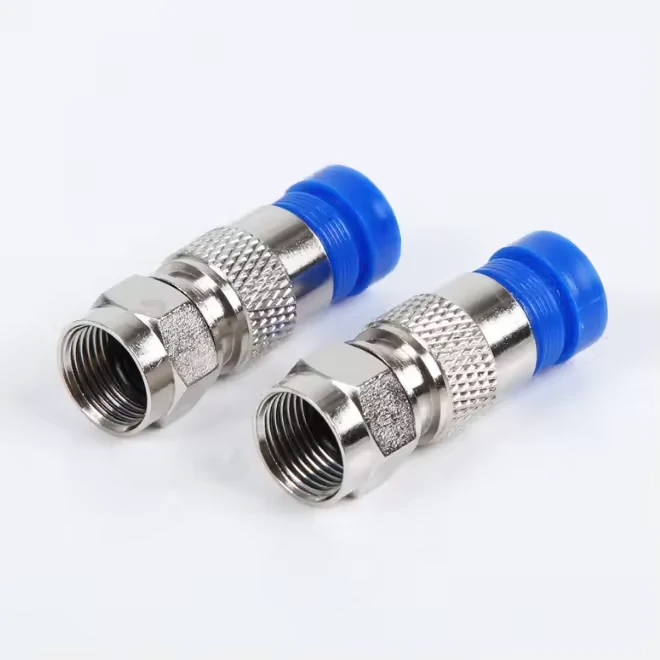
Pair of RG6 compression F connectors featuring blue rear sealing sleeves. Proper installation depends on cable outside diameter, shield stack, strip dimensions, and compression-tool stroke.
A connector can start onto the cable and still be the wrong connector.
This is common with compression designs because initial insertion does not prove that the cable will reach the internal stop or that the rear sleeve will compress correctly.
The fit needs to be evaluated where the connector actually grips the cable.
Measure the cable where the rear sleeve actually grips
For a compression F connector, the critical fit area is usually toward the rear of the connector body, where the cable and shield stack are captured during compression.
Check the complete preparation condition, not only the untouched cable OD.
Depending on the design, the relevant stack may include:
- outer jacket;
- foil;
- braid;
- folded-back braid;
- dielectric;
- and the connector’s internal or rear compression sleeve.
This is also why one generic strip procedure should not automatically be copied between different RG6 constructions. Changing the braid or foil arrangement can change how much material occupies the rear body.
Watch for quad-shield builds that enter the body but do not seat correctly
Quad-shield cable deserves particular attention.
A technician may be able to force the cable into a connector intended for a thinner shield stack. The problem then moves deeper into the assembly.
Typical warning signs include unusually high insertion force, jacket wrinkling, braid displacement, exposed shield strands, or a sleeve that stops short of its specified compressed position.
Forcing the connector farther is not a qualification method.
If the assembly requires inconsistent hand force from one cable batch to another, check cable and connector dimensions before adjusting the tool.
Reject “fits RG6” as the only compatibility statement
For field repair, a broad compatibility statement may be acceptable when the installer is working with known commercial cable families.
For OEM production, repeat assemblies, or purchased cable harnesses, the specification should be tighter.
A useful supplier compatibility statement identifies:
- cable manufacturer or cable P/N;
- shield configuration;
- allowed cable OD range;
- connector P/N;
- and, where relevant, the recommended preparation and compression tooling.
The useful result is not that one connector looks universal.
The useful result is knowing exactly which cable constructions have been tested and released with it.
How do you qualify a compression F connector before approving the tool?
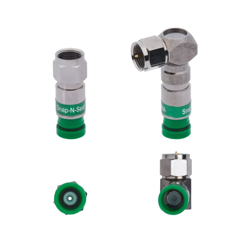
A connector should be qualified on the cable before the compression tool is approved.
Reversing that order creates a common production problem: the tool is adjusted until the finished connector looks acceptable, even though the cable was never fully seated inside the connector body. The result can be visually clean but mechanically or electrically wrong.
For an RG6 compression connector, qualification starts in the uncompressed state.
Verify cable seating before compression begins
After cable preparation, insert the RG6 into the connector and inspect four points:
- the cable reaches the connector’s intended internal stop;
- the dielectric reaches the expected position;
- the braid and foil remain controlled;
- the jacket enters the rear sleeve without bunching or folding.
Do not use the compression tool to compensate for incomplete insertion.
If excessive tool force is required to pull the connector into position, the problem may be cable-to-connector fit rather than tool adjustment.
This distinction matters because an F type compression connector has two separate compatibility relationships:
Cable ↔ Connector Connector ↔ Compression Tool
Passing one does not prove the other.
A connector can fit the cable correctly but still require a different anvil, stroke, or compression mechanism.
Measure the connector before and after compression
Visual inspection is useful, but it should not be the only process control.
Record measurable features such as:
- initial connector length;
- finished connector length;
- cable insertion depth;
- sleeve position;
- center conductor projection.
A production operator may describe two connectors as “fully compressed” even when their final sleeve positions differ.
Dimensions make the decision less subjective.
For a new cable–connector combination, save several approved first-article samples and record their finished dimensions. Those samples become a practical reference when tools are replaced, repaired, or moved between production lines.
Use a three-part approval gate
A useful release rule is:
- Cable ↔ Connector Fit
- Connector ↔ Tool Fit
- Finished Termination ↔ Acceptance Limit
All three must pass.
If the cable fits but the tool leaves the sleeve short, reject the combination.
If the tool produces the expected finished length but the cable was not fully inserted, reject it.
If the mechanical assembly looks correct but electrical verification fails, reject it.
That three-part gate is more useful than approving each component independently.
When should a “universal RG6 connector” be rejected?
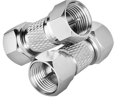
Close-up of three metal twist-on RG6 F connectors. Cable diameter, shield construction, and center conductor projection should be checked before installation.
“Universal” can be a convenient catalog description. It should not become an engineering assumption.
For field installation, a connector capable of handling several common RG6 constructions may reduce inventory and make service work easier. Production approval needs stronger evidence.
Reject it when supported cable dimensions are not defined
A supplier claiming compatibility with “all RG6” should still be able to provide some physical basis for the claim.
Useful information includes:
- supported cable OD range;
- supported shield configurations;
- center conductor limits;
- required preparation geometry;
- compatible compression method.
Without those limits, the word universal gives purchasing very little control over substitution.
The better production statement is:
Approved for Cable P/N A, Cable P/N B, and Cable P/N C using Connector P/N X and Tool P/N Y.
That is auditable.
Reject uncontrolled insertion force
Insertion force is another useful warning.
Operators should not need one technique for one RG6 reel and substantially more hand force for another supposedly equivalent reel.
High insertion force can cause:
- shield displacement;
- jacket damage;
- incomplete seating;
- excessive operator variation;
- hidden damage before compression.
Production does not need every insertion force to be identical, but the process should be stable enough that operators are not forcing some assemblies together.
A practical substitution decision can follow this sequence:
Universal Connector Approval Tree
- Exact cable construction tested?
- Dimensions within the connector’s approved range?
- Cable reaches full insertion position?
- Compression tool produces the required finished state?
- Mechanical retention passes?
- Electrical inspection passes?
If one answer is No, do not release the substitution.
How do you set center-conductor projection without copying a generic strip length?
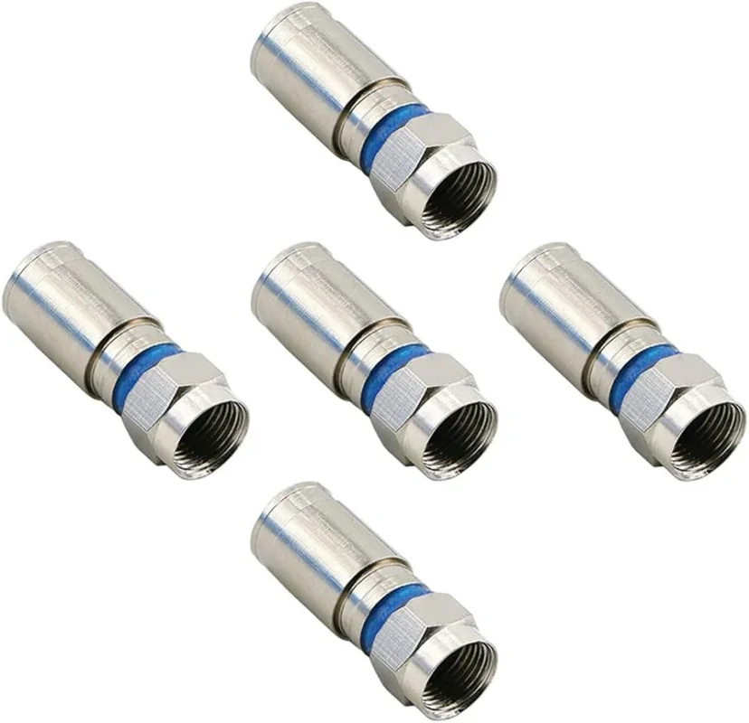
An F-type cable termination is unusual because the coaxial cable’s own center conductor becomes part of the male mating interface.
That makes cable preparation more than a convenience for assembly. It directly affects the finished interface.
Copying a strip length from another RG6 cable or connector is therefore risky.
Use the finished interface as the dimensional reference
Separate the preparation into four dimensions:
- jacket strip length;
- shield preparation;
- dielectric exposure;
- finished center conductor projection.
These dimensions interact, but they are not interchangeable.
If the cable sits deeper inside one connector design than another, identical pre-compression strip dimensions may produce a different finished conductor projection.
The correct inspection point is the completed termination.
Inspect again after compression
Compression can slightly change cable seating and dielectric position.
For that reason, checking center conductor length only before compression leaves a gap in process control.
A production record can look like this:
The exact limits should come from the approved connector design, cable preparation specification, and application requirement rather than a generic online stripping diagram.
This is also where F connector dimensions become useful to purchasing and quality teams: not as isolated catalog numbers, but as measurable acceptance points for the finished assembly.
Which tool variables determine a repeatable compression?
Buying the correct F connector tool does not finish the process.
Tool configuration still has to match the connector geometry.
The most useful approach is to separate preparation tooling from compression tooling.
Control the full tool chain
Depending on the production setup, the process may involve:
- cable cutter;
- strip or preparation tool;
- F compression tool;
- connector holder or anvil;
- dimensional gauge.
The stripping tool matters because it controls what enters the connector.
The compression tool matters because it controls the final body position.
A problem in either one can produce a failed termination.
Verify stroke against the connector body
Avoid using:
It looks fully compressed.
as the acceptance standard.
Instead, document the tool setting and correlate it with the connector’s finished condition.
A basic control table may include:
Tool qualification should also be repeated after a relevant change.
Typical triggers include a replacement compression tool, changed anvil, connector supplier change, cable supplier change, tool repair, or an abnormal pull-test result.
That prevents an old setup from being treated as permanently valid after the surrounding components have changed.
How should a 75-ohm RG6 termination be verified beyond continuity?
Continuity is useful. It is not an RF performance test.
A continuity check can find a broken center conductor, an open shield, or a gross center-to-shield short. Those checks belong in production.
But passing them does not prove that the finished 75 ohm F connector transition behaves correctly in the intended frequency range.
Verify the complete 75-ohm path
A real installation may look like:
Device → F connector → RG6 → splitter or passive component → F connector → device
Every transition contributes to the final path.
A connector that looks correct at the bench can still cause problems if shield contact is poor, the center conductor geometry is wrong, or the finished interface creates excessive mismatch at the operating frequency.
For Type F interfaces used in 75-ohm cable networks, IEC 61169-24 provides the relevant connector-interface framework, including interface dimensions, gauges, and mandatory tests. The practical production lesson is simple: continuity should be treated as the first electrical gate, not the last one.
Build electrical acceptance in stages
A useful inspection ladder is:
- Center continuity
- Shield continuity
- No center-to-shield short
- 75-ohm path confirmed
- Application-frequency signal or RF test
- Installed-state verification when the application requires it
Not every low-cost assembly needs a full laboratory VNA report.
The test depth should match the product claim and application risk.
A CATV jumper, broadband assembly, laboratory reference cable, and internal OEM harness may use different acceptance limits. What should remain consistent is the logic: mechanical fit and DC continuity cannot, by themselves, certify the RF path.
Account for higher-frequency HFC networks before freezing the connector BOM
A connector that works on a basic continuity check should not automatically be released for every CATV or broadband application.
The upper end of the coaxial spectrum is becoming more demanding. CableLabs describes Extended Spectrum DOCSIS 4.0 operation up to 1.8 GHz, while its 2026 technology update says industry work is underway on an extension of DOCSIS 4.0 solutions toward 3 GHz. That 3 GHz work should be treated as an evolving extension, not as proof that every existing RG6 cable, splitter, wall plate, or F connector is automatically suitable to 3 GHz.
IEC 61169-24:2019 is also relevant here. The Type F sectional specification covers screw-coupled RF connectors typically used in 75-ohm cable networks, and the 2019 edition states that its drawings were reworked to allow frequency extension up to 3 GHz.
Test to the frequency the finished assembly actually claims
Do not turn those industry figures into a generic product claim.
A finished broadband path may include:
RG6 cable → F connector → wall plate → splitter → F connector → modem
The usable frequency range is limited by the complete path, not by the connector interface name alone.
Before releasing a BOM for a higher-frequency HFC application, record the rated or tested band for each relevant component.
This RG6 Connector Frequency Readiness Sheet prevents one 3 GHz-rated component from being used to imply that the complete assembly is 3 GHz capable.
How do dual- and quad-shield builds change production controls?
Once different RG6 constructions are approved, do not assume they should share an identical work instruction.
If braid fold-back, foil handling, strip dimensions, or connector insertion differ, separate those operations clearly.
Inspect the shield before compression hides the defect
Compression makes many preparation errors difficult to see.
The pre-compression inspection should therefore catch displaced foil, cut braid, loose strands, incorrect fold-back, and damaged jacket before the connector body covers them.
This is especially useful when a production line runs both dual-shield and quad-shield cable.
Track their results separately as well. If quad-shield assemblies show more insertion failures while dual-shield assemblies remain stable, a combined first-pass yield number can hide the actual process problem.
A simple workstation record can include cable construction, approved strip program, shield condition, connector insertion status, operator, and date.
Validate retention without mistaking pull force for signal quality
A strong pull result is useful. It does not prove a good RF termination.
Before setting a pull requirement, define the test method: fixture, pull direction, free cable length, test rate, and whether the test is destructive or non-destructive.
More important, record where the assembly fails.
Cable slippage, jacket tearing, connector-body separation, and center-conductor movement are not equivalent failure modes.
A practical production record keeps mechanical and electrical results side by side:
An assembly can be mechanically strong and electrically poor. It can also pass an RF check while having inadequate retention.
Keep both acceptance limits independent.
How should alternate cable or connector suppliers be qualified?
A supplier change should be treated as a process change until comparison proves otherwise.
A new cable may still say RG6 75 Ω while using a different jacket diameter, braid coverage, dielectric geometry, or center conductor.
Likewise, a replacement compression F connector may look interchangeable from the front but use a different rear sleeve, internal stop, or required compression stroke.
Compare the alternate against a golden combination
Keep one approved cable–connector–tool combination as the reference.
Then compare the substitute against it.
Catalog wording such as RG6-compatible, universal, or compression-ready is not a substitute for this qualification.
This rule is particularly useful when purchasing changes suppliers to solve a lead-time or cost problem. A commercial substitution should not quietly become an uncontrolled manufacturing change.
Build a production-ready RG6 connector specification
The cleanest way to control an RG6 F connector assembly is to stop treating cable, connector, and tooling as three unrelated purchasing items.
Lock them together.
A production RFQ or BOM should identify the cable manufacturer and P/N, shield construction, connector P/N, termination method, approved preparation tool, approved compression tool, and finished-state inspection requirements.
The final record can look like this:
That record also makes future substitutions easier to manage. Purchasing can immediately see which parameters must be rechecked instead of relying on a connector photo or a broad “for RG6” description.
The production rule can be reduced to one line:
Approved Cable P/N + Approved Connector P/N + Approved Tool P/N = Approved termination system.
Change one part of that system and determine whether requalification is required.
FAQ
Can two RG6 cables with the same 75-ohm rating require different F connectors?
Yes. The RG6 designation does not fully define jacket OD, dielectric dimensions, center conductor, or shield stack. Connector approval should therefore reference the actual cable part number and construction rather than impedance and family name alone.
Does quad-shield RG6 always need a different compression connector?
Not necessarily. Some connector designs support several shield constructions. Do not assume interchangeability, though. Confirm the allowed cable dimensions, shield configuration, insertion condition, and finished compression result for the actual quad-shield cable.
Can an F connector fit the cable but still be incompatible with the compression tool?
Yes. Cable-to-connector fit and connector-to-tool fit are separate relationships. The connector can seat correctly on the RG6 while the available tool uses the wrong stroke, anvil, or body support.
Does a high pull-test result prove the termination is electrically good?
No. Pull testing evaluates mechanical retention. It does not confirm the quality of the 75-ohm transition or the assembly’s RF behavior at the intended operating frequency.
Should changing the RG6 cable supplier trigger requalification?
It should trigger a review. If jacket OD, shield construction, dielectric geometry, center conductor, or preparation behavior changes, repeat the relevant fit, compression, dimensional, retention, and electrical checks.
Does DOCSIS 4.0 make F-connector validation more demanding?
It increases the reason to pay attention to higher-frequency behavior. CableLabs identifies Extended Spectrum DOCSIS 4.0 operation up to 1.8 GHz and reported in February 2026 that work is progressing toward an extension to 3 GHz. For broadband assemblies, the cable, F connectors, splitters, and other passive components therefore need to be evaluated against the band the finished system actually uses.
Can a “universal RG6 connector” be approved without testing every cable construction?
For controlled production, broad catalog compatibility is not enough. Qualify the specific cable constructions that will actually enter the BOM and document their approved connector and tooling combination.
Final practical note
The most expensive RG6 termination error is rarely the connector itself. It is approving an incomplete specification and discovering the mismatch after hundreds or thousands of assemblies have been built.
Before ordering production quantities, send the supplier the exact RG6 cable P/N, shield construction, relevant cable dimensions, required F connector style, application frequency, environmental requirement, and inspection target.
If the connector is compression type, include the approved tool information as well.
That gives engineering, purchasing, and production the same definition of an acceptable assembly—and makes a later substitution much easier to control.
