
A technician installs the adapter, the BNC bayonet locks normally, and the F connector threads on without resistance. Mechanically, everything appears correct.
The picture still does not appear.
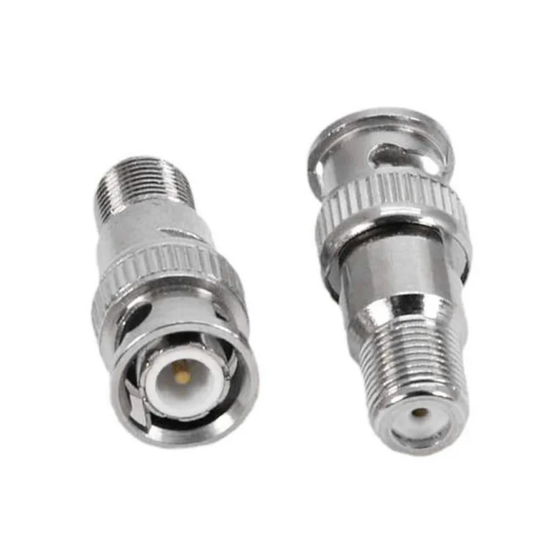
This is where many BNC-to-F projects go wrong. A BNC to F type adapter only changes the physical connector interface. It does not prove that the connector genders are correct, that both systems use 75-ohm impedance, or that the connected devices carry the same signal format.
A working connection requires four separate checks:
- The exact gender on both equipment ports
- The impedance of the BNC and F-type signal paths
- The format carried by the coaxial cable
- The mechanical load placed on the equipment port
Skipping any one of these checks may produce a connection that fits but does not operate correctly.
Which Port Pair Are You Actually Adapting?
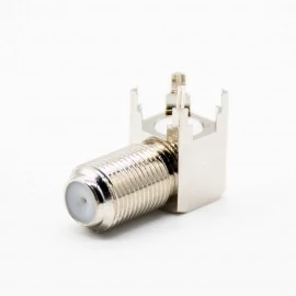
This right-angle F-type female connector is designed for PCB installation where limited enclosure depth or cable routing requires a 90-degree coaxial interface. Its external thread mates with an F male cable connector.
“BNC to F” is not a complete product description.
A supplier still needs to know whether the BNC side is male or female and whether the F-type side is male or female. There are four possible combinations, and they are not interchangeable.
Before searching for an adapter, inspect the ports on the actual equipment. Do not rely only on the cable description, signal direction, old purchase records, or wording such as “camera input” and “TV output.”
Record the following:
- Connector family on Device A
- Connector gender on Device A
- Connector family on Device B
- Connector gender on Device B
- Whether each interface is equipment-mounted or cable-mounted
- Whether the installation needs a straight or right-angle transition
The adapter must provide the mating gender for each port.
For example, a BNC female equipment jack requires a BNC male adapter end. An F female equipment port requires an F male adapter end.
BNC-to-F Gender Selection Matrix
| Equipment BNC Port | Equipment F Port | Adapter Required |
| BNC Female | F Female | BNC Male to F Male |
| BNC Female | F Male | BNC Male to F Female |
| BNC Male | F Female | BNC Female to F Male |
| BNC Male | F Male | BNC Female to F Female |
| Unknown | Unknown | Inspect both ports before ordering |
The two most commonly searched versions are a BNC female to F male adapter and a BNC male to F female adapter, but search popularity does not tell you which one fits your system.
A useful purchasing rule is simple: never approve an adapter from a product title alone. Ask for a drawing or a clear photograph showing both center contacts and both coupling structures.
How Do You Read BNC Gender Without Guessing?
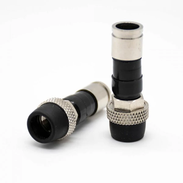
A pair of F-type coaxial cable connectors designed for RG6 cable termination. The RG6 cable must be fitted with a compatible connector before it can connect reliably to a standard BNC-to-F type adapter.
The BNC side should be checked in two places: the center contact and the bayonet coupling structure.
A conventional BNC male plug normally has a center pin and a rotating bayonet coupling sleeve. A BNC female jack normally has a center socket and the external bayonet lugs that receive the plug.
The center contact is usually the fastest inspection point:
- Center pin: normally male
- Center socket: normally female
Then check the outer coupling structure as a second confirmation.
This matters because product photographs can be misleading. A large outer body does not automatically mean male, and a panel-mounted connector does not automatically mean female. Cable plugs, bulkhead jacks, in-line adapters, and reverse configurations may look different from the examples a buyer remembers.
The words “input” and “output” should never be used as gender descriptions.
A CCTV camera may have a female BNC output jack. A test instrument may also use a female BNC port. The signal leaves one device and enters another, but both equipment ports can still use the same connector gender.
Signal direction and connector gender are independent fields.
BNC also exists in both 50-ohm and 75-ohm versions. The interface may mate mechanically even when the impedance is not suitable for the application. TE Connectivity lists BNC plugs and jacks in both impedance families, which is why visual fit alone is not enough.
For a broader explanation of where BNC is used, see the BNC connector overview.
How Do You Decode the F-Type Side Correctly?
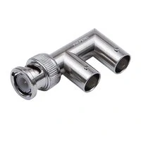
This right-angle BNC T adapter provides one BNC male connection and two BNC female branches. It adds extra interfaces to the coaxial signal path and should not be treated as an impedance-matched splitter unless its electrical specifications confirm that function.
F-type gender causes a different kind of confusion because the center conductor is not always a separate manufactured pin.
Many F male cable connectors use the coaxial cable’s own center conductor as the mating contact. The cable conductor extends through the front of the connector and enters the socket inside the F female port.
The threaded structure gives the more reliable gender clue.
An F male plug normally has a rotating internal-thread coupling nut. It screws onto the external threads of an F female jack. The F female side usually has the fixed external thread found on televisions, splitters, set-top boxes, modems, and wall plates.
Do not assume every exposed conductor means the connector itself has a conventional male pin. On many RG6 cable assemblies, the conductor is simply the prepared cable core.
The connector and cable must also be checked separately.
An adapter that mates with an F connector does not prove that the existing connector was properly selected or installed for the cable. An RG6 connector may use compression, crimp, or twist-on termination. Each version has its own dimensional and installation requirements.
Check:
- RG6, RG59, or another coaxial cable
- Cable outside diameter
- Center conductor preparation
- Braid and foil placement
- Compression or crimp completion
- Thread condition
- Shield continuity
The coax connector types guide provides additional background on the differences among BNC, F-type, TNC, FME, and television coaxial interfaces.
Does the BNC Side Belong to a 50-Ohm or 75-Ohm System?
This check should happen before the adapter is purchased.
F-type interfaces are normally associated with 75-ohm coaxial systems, including cable television, broadband distribution, television antennas, satellite receiver paths, and many RG6 installations.
BNC is less predictable.
It may be used in:
- 50-ohm RF laboratory equipment
- Radio communication systems
- Signal generators
- Oscilloscopes and test equipment
- 75-ohm CCTV systems
- Analog video
- Broadcast video
- SDI systems
- Other coaxial measurement paths
A BNC connector on a piece of equipment does not identify the impedance by itself.
The safest source is the equipment manual, datasheet, rear-panel marking, or approved system drawing. If the impedance is not documented, ask the equipment manufacturer or measure the port using an appropriate RF method.
A normal passive BNC-to-F adapter does not contain an impedance transformer merely because one end is BNC and the other is F-type.
It normally changes:
- Connector family
- Mating structure
- Mechanical coupling
- Physical interface gender
It normally does not provide:
- A 50-to-75-ohm transformer
- A matching network
- An attenuation pad
- Signal amplification
- Filtering
- Modulation or demodulation
System-Impedance Approval Gate
A short mismatched connection may appear to work at a lower frequency or in a system with generous signal margin. That does not make the impedance error disappear.
For more detail on BNC cable impedance and application differences, review the BNC cable selection guide.
Can a BNC to F Type Adapter Connect Directly to RG6?
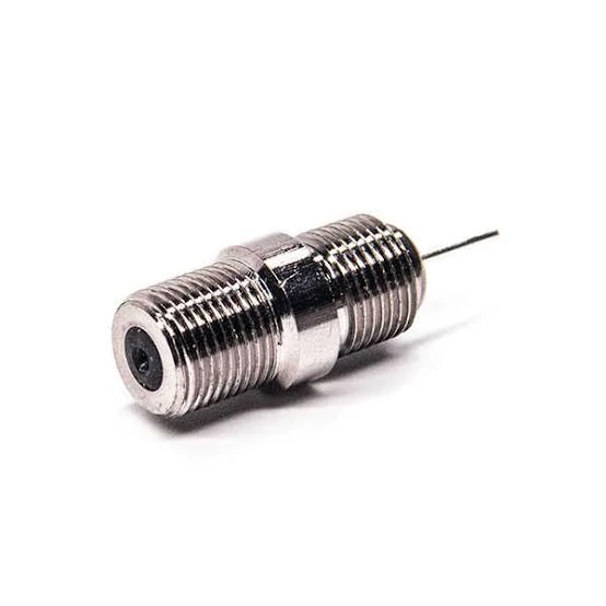
This straight F-type female connector provides an externally threaded interface for mating with an F male plug. The rear pin allows the center conductor to be connected inside RF, television, broadband, or coaxial equipment.
The phrase BNC to RG6 adapter is widely used, but it is often technically incomplete.
RG6 is a cable type. F is a connector family.
In most cases, a buyer searching for a BNC-to-RG6 adapter actually needs an adapter that connects a BNC interface to an F connector already installed on RG6 cable.
A standard in-line adapter cannot connect directly to an unfinished piece of bare RG6 unless the product includes a cable-termination structure designed for RG6.
That structure may be:
- A compression fitting
- A crimp ferrule
- A clamp body
- A cable-entry connector
- A custom cable assembly termination
RG6 Connection Decision Table
When the RG6 end is unfinished, there are usually three sensible options.
First, terminate the cable with a proper F connector and then add the adapter. This is convenient when the system already uses F-type tooling and replacement parts.
Second, install a BNC connector specifically designed for the RG6 construction and impedance. This reduces the number of interfaces, but the connector must match the cable diameter, dielectric, shield construction, and termination method.
Third, order a complete BNC-to-F or BNC-to-RG6 cable assembly. This is often the cleaner choice for permanent installations.
The RG cable guide explains how RG6 differs from smaller RF coaxial cables and why cable construction remains relevant after the interface is changed.
When Does a Passive Adapter Work Without a Converter?
A passive adapter may be suitable when both connected devices already use the same signal standard and compatible impedance.
Examples may include:
- A compatible 75-ohm video path
- A compatible television antenna signal
- A CATV RF path
- A broadband coaxial connection
- Certain CCTV systems
- A temporary test connection to a compatible signal
The phrase “may be suitable” is deliberate. The connector does not define the complete signal.
A passive BNC-to-F adapter cannot automatically perform:
- Cable-TV channel tuning
- RF demodulation
- Composite-video conversion
- SDI decoding
- Satellite receiver functions
- Digital-to-analog conversion
- Encryption decoding
- Frequency translation
Suppose an F connector carries a cable-TV RF feed and the BNC port belongs to a composite-video monitor. Both sides may use 75-ohm coaxial structures, but the signals are not the same.
The monitor expects baseband video. The cable feed contains modulated television channels. A tuner or receiver is required between them.
The same rule applies when connecting SDI equipment, security cameras, laboratory generators, television antennas, broadband modems, and other coaxial devices.
Passive Compatibility Decision Tree
Write down the complete path before approving the connection:
Signal source→ Source connector→ Adapter→ Coaxial cable→ Splitter or coupler→ Destination connector→ Destination input→ Termination This exposes problems that remain hidden when the request is reduced to “please supply a BNC-to-F adapter.”
How Much Mismatch Can the Signal Chain Tolerate?
A 50-ohm BNC source connected to a 75-ohm load creates a theoretical impedance discontinuity, even when the adapter is well manufactured.
For a simple impedance transition, the voltage reflection coefficient can be estimated as:
This calculation is a screening tool, not a complete prediction of installed performance.
The real result also depends on:
- Frequency
- Cable length
- Source termination
- Load termination
- Adapter geometry
- Connector wear
- Cable quality
- Additional couplers
- Splitters
- Equipment input networks
- Calibration reference plane
At low frequencies, the system may tolerate the mismatch. At higher frequencies, repeated transitions and poorly controlled connector geometry become harder to ignore.
Count every interface.
A path may contain:
BNC Source→ BNC-to-F Adapter→ F Barrel Coupler→ RG6 Cable→ Two-Way Splitter→ F Input Each additional interface can add reflection, insertion loss, contact variation, and another possible failure point.
Continuity testing will not reveal all of these RF effects. A part can show perfect center and shield continuity while still producing unacceptable return loss in the operating band.
Should You Use a Rigid Adapter or a Short Pigtail?
A rigid adapter is compact and convenient. It is not automatically the safest mechanical choice.
RG6 is relatively thick and stiff compared with small laboratory coaxial cables. When a heavy RG6 cable hangs from a rigid BNC-to-F adapter, the adapter becomes a lever attached to the BNC equipment port.
That load can cause:
- Port movement
- Bayonet wear
- Intermittent shield contact
- Center-contact misalignment
- Body loosening
- Damage during accidental cable impact
A rigid adapter works best when the two interfaces are close, aligned, supported, and free from side load.
A short pigtail is usually safer when:
- The RG6 approaches from the side
- The equipment port is recessed
- The cable cannot bend naturally
- Adjacent ports are closely spaced
- The installation is permanent
- The equipment may move or vibrate
- A straight adapter would block access
| Installation Requirement | Rigid Adapter | Short Pigtail |
| Directly aligned ports | Preferred | Optional |
| Heavy or stiff RG6 cable | Higher port stress | Preferred |
| Limited rear clearance | May be difficult | Easier to route |
| Temporary bench use | Preferred | Suitable |
| Permanent installation | Requires support | Usually safer |
| Vibration exposure | Higher leverage | Better isolation |
| Custom length | Not available | Available |
| Offset connection | Poor fit | Preferred |
Do not solve a gender or alignment problem by stacking several adapters unless the installation is temporary and carefully supported.
Instead of:
BNC Port→ BNC Gender Changer→ BNC-to-F Adapter→ F Coupler→ RG6 Use:
BNC-to-F Pigtail
or:
Custom BNC-to-RG6 Cable Assembly
The one-piece assembly reduces interfaces and moves cable stress away from the equipment connector.
How Do You Protect Both Ports From Mechanical Load?
Measure the installed envelope, not only the loose adapter.
An adapter that fits on the workbench may become difficult to install inside a rack, enclosure, camera housing, wall box, or closely spaced equipment panel.
Check:
- Total installed adapter length
- BNC bayonet rotation clearance
- F connector finger or wrench clearance
- RG6 bend space
- Adjacent connector spacing
- Enclosure depth
- Cable support location
- Service-loop allowance
The BNC side needs enough room for the coupling sleeve to rotate. The F side needs enough space for the cable connector to thread fully without cross-threading.
Support the RG6 cable before it reaches the adapter.
Useful methods include:
- Cable clamps
- Tie-down points
- Strain-relief brackets
- Service loops
- Panel support
- Flexible pigtails
- Correctly positioned cable guides
Avoid forcing the cable into a bend immediately behind the F connector. The cable may push continuously against the adapter even when the equipment is stationary.
After installation, inspect for:
- Body rotation
- Loose bayonet sleeve
- Damaged F threads
- Misaligned center contact
- Loose dielectric
- Plating wear
- Cable-induced movement
A stable connection should remain mechanically quiet when the cable is moved lightly within its normal service range.
How Should Samples Be Verified Before Approval?
Start with the drawing.
Confirm:
- BNC male or female
- F male or female
- Nominal impedance
- Straight or right-angle orientation
- Body material
- Contact plating
- Insulator material
- Overall installed dimensions
Then inspect the sample against the drawing rather than against the product name.
For a normal straight-through adapter, basic electrical checks should include:
- BNC center to F center continuity
- BNC shell to F outer-conductor continuity
- Center-to-shell isolation
These checks identify open circuits, shorts, incorrect assembly, and some contact problems. They do not prove high-frequency performance.
The functional test should use the intended equipment and cable chain.
A practical sequence is:
- Record the system result without the new adapter, when possible.
- Insert the BNC-to-F adapter.
- Check signal level, picture stability, data behavior, or instrument reading.
- Move the RG6 cable lightly near the adapter.
- Disconnect and reconnect both interfaces.
- Repeat the test on several samples.
- Record the worst result rather than only the best sample.
Where signal margin is limited, use a VNA or suitable RF test system to measure return loss and insertion loss across the required frequency range.
The fixture, calibration plane, mating connectors, and test cables must be controlled. Otherwise, the result may reflect the test setup more than the adapter.
A bulk-order approval record can use the following fields:
Sample approval should also define whether production lots require continuity inspection, dimensional sampling, VNA data, first-article inspection, or lot traceability.
What Must Be Written on the RFQ?
Do not write only:
BNC to F Adapter
That description leaves too many decisions to the supplier.
A better RFQ begins with the complete interface combination:
BNC Male to F Female Adapter Straight 75 Ohm
or:
BNC Female to F Male Adapter Straight 75 Ohm
The application should also be stated. A supplier may need different technical evidence for a television antenna path, a CCTV installation, a broadband system, a broadcast-video connection, or a laboratory signal.
Use an RFQ block such as:
Connector requirements and cable requirements should remain separate.
For the adapter, specify interface gender, impedance, orientation, dimensions, frequency, material, plating, and test requirements.
For the cable, specify RG type, outside diameter, installed connector, route, bend space, length, shielding, and environmental conditions.
A supplier cannot reliably fill these gaps from a short product title.
FAQ
Can a BNC-to-F adapter connect a 50-ohm signal generator to RG6?
It can make the physical connection if the genders fit, but standard RG6 and F-type systems are normally 75 ohms. The passive adapter does not remove the impedance discontinuity. The connection may still function for some low-frequency or non-critical tests, but return loss, amplitude accuracy, and measurement uncertainty should be reviewed before relying on it.
Does “F to BNC adapter” describe a different signal direction?
No. A simple passive adapter is normally bidirectional. The wording usually reflects which connector the buyer starts with. What matters is the complete gender combination, impedance, signal format, and intended source-to-load path. “F to BNC” and “BNC to F” may describe the same physical part.
Can the adapter connect directly to bare RG6 coax?
Usually not. A standard adapter expects an existing connector. Bare RG6 must first be terminated using a compatible F connector, BNC connector, compression fitting, crimp structure, or custom cable assembly. Pushing an unfinished cable conductor into an adapter is not a controlled or reliable termination method.
Why is an F male connector difficult to identify?
Many F male cable connectors use the coaxial cable’s center conductor as the contact instead of a separate manufactured center pin. That can confuse buyers who use only the center contact to judge gender. Check the rotating internal-thread nut: it mates with the external thread on an F female port.
Can a BNC-to-F adapter convert cable television into composite video?
No. Cable television RF and composite video are different signal formats. The adapter only changes the physical connector interface. A tuner, demodulator, receiver, or other active device is required to convert or decode the signal before it reaches a composite-video input.
When is a short BNC-to-F pigtail better than a rigid adapter?
Use a pigtail when the RG6 cable is heavy, stiff, offset, tightly routed, or likely to move. The flexible section reduces leverage on the BNC port and makes installation easier in confined spaces. It is also useful when a rigid adapter would block nearby connectors.
What should be tested before approving a bulk order?
Verify both genders, impedance, dimensions, center continuity, shield continuity, center-to-shield isolation, BNC retention, F thread engagement, body tightness, and actual system operation. Add return-loss and insertion-loss measurements when the application has a defined RF limit or narrow performance margin.
Final Selection Note
A BNC to F type adapter should be selected as part of the signal chain, not as an isolated piece of hardware.
Before ordering, confirm:
- The exact gender of both equipment ports
- Whether the BNC system is 50 or 75 ohms
- Whether the F-type path and RG6 cable are 75 ohms
- Whether both devices use the same signal format
- Whether the installation needs a rigid adapter or a pigtail
- Whether the cable is supported
- Which inspection and RF tests are required
The part may mate, pass continuity, and still be wrong for the application.
For a production request, send the equipment-port photographs, required genders, impedance, operating frequency, signal type, connected cable, dimensional limits, and acceptance target. That information gives the supplier enough detail to confirm the interface instead of guessing from “BNC to F.”
