
A BNC cable may fit the test instrument perfectly but still be useless at the other end of the setup. This usually becomes apparent when an engineer tries to connect existing laboratory equipment to a wireless module fitted with an SMA or RP-SMA port.
Replacing the entire cable assembly is one option. It is not always the sensible one, particularly when the original cable is already installed in a test fixture or connected to other equipment. A suitable adapter can bridge the interface difference without requiring changes to the existing setup.
A BNC to SMA adapter is often used for this purpose. The difficulty is that SMA and RP-SMA are not interchangeable configurations. Their external appearance can be misleading, and ordering based on connector names alone is a common source of sourcing errors.
For engineers working with RF test equipment, antenna systems, and wireless hardware, the first job is to establish exactly what is installed at each end.
When Does a BNC-to-SMA Adapter Solve an RF Connection Problem?
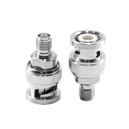
BNC to SMA coaxial adapter featuring precision metal connector interfaces for RF signal connections between compatible devices and test equipment.
Not every interface mismatch requires a new cable. Sometimes the existing assembly is perfectly serviceable, but its connector does not match the equipment being tested.
BNC connectors use a bayonet coupling mechanism, while SMA connectors use a threaded coupling. The mechanical difference is straightforward. What requires more attention is the electrical configuration and the connector arrangement on the receiving device.
Connecting Laboratory Equipment to Wireless Devices
Consider a test bench with a signal generator using a BNC output and a wireless communication module equipped with an RP-SMA antenna port.
The engineer already has a suitable coaxial cable. The only missing component is the transition between the two interfaces.
A compatible adapter can complete the connection. However, three details should be checked before the test begins:
- The BNC side must match the cable or instrument port.
- The SMA-family side must match the actual device interface, including polarity.
- The impedance must be appropriate for the intended RF circuit.
There is another detail that sometimes gets overlooked: the instrument itself must support the frequency and signal level being tested. A connector adapter cannot extend the operating range of a signal generator or improve the measurement capability of an oscilloscope.
Reusing Existing BNC Cable Assemblies
In production environments, changing an established cable assembly can create more work than expected. The cable may be part of a test fixture, mounted inside an enclosure, or connected to equipment that is not easy to access.
A short adapter is often a practical alternative.
Take an existing RG316 cable with BNC connectors. If the receiving equipment has an SMA interface, a correctly specified BNC-to-SMA transition may allow the cable to remain in service.
The cable itself still needs to be checked. RG316 is commonly used in compact RF assemblies, but its attenuation increases with frequency and cable length. Adding an adapter also introduces another connection point into the signal path.
For a short laboratory connection, this may be acceptable. For a sensitive measurement, the complete assembly should be evaluated rather than treating the adapter as an electrically invisible component.
Why Connector Gender and Polarity Must Be Checked Separately
A product listing that says BNC male to RP-SMA male does not provide enough information for every purchasing decision.
The two ends must be considered independently. BNC male and female describe the bayonet-side mating arrangement. SMA and RP-SMA require an additional check of the center contact.
Reverse-polarity SMA changes the relationship between the center contact and the external mating structure. It is not simply another name for a standard SMA connector.
This distinction matters when the adapter is being purchased for a specific antenna port or wireless module. Two connectors may appear almost identical in a catalogue photograph but have different mating configurations.
The safest approach is to request a dimensional drawing or a clear interface photograph from the supplier. For repeat orders, retain the approved drawing alongside the BOM instead of relying on a shortened product description.
How Do You Map a BNC Port to an RP-SMA Interface?
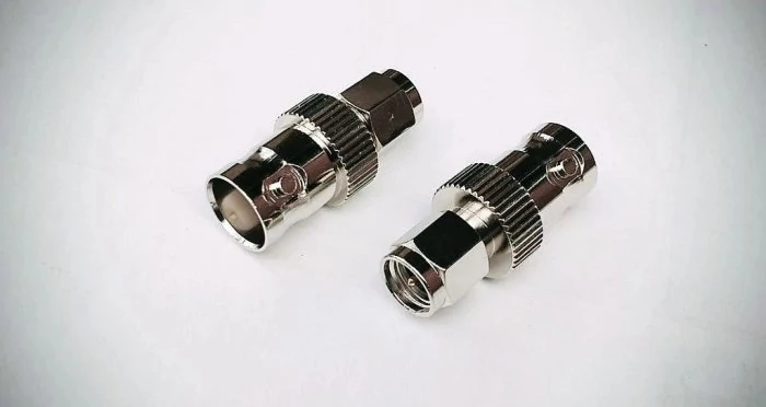
BNC to SMA RF connector adapters provide a practical interface transition for laboratory instruments, coaxial cables, and wireless communication equipment.
Start with the equipment connection, not the adapter product name. Identify the connector installed on the instrument, then inspect the receiving device. This avoids a surprisingly common mistake: selecting an adapter that has the correct connector families but the wrong mating arrangement.
A useful reference is the following interface identification table.
| Connection point | Details to verify |
| BNC equipment port | Male or female |
| BNC cable end | Plug or jack |
| Device-side interface | SMA or RP-SMA |
| Center contact | Pin or socket |
| Impedance | 50 Ω or 75 Ω |
| Installation | Direct connection or cable jumper |
The table is intentionally simple. These are the details a purchasing team should establish before requesting a quotation.
Check the BNC Bayonet Connection First
BNC connectors lock through a quarter-turn bayonet mechanism. The mating parts need to align correctly before the coupling is rotated into position.
A loose connection, damaged bayonet slot, or worn contact can cause intermittent behavior during testing. If an existing cable has been used repeatedly, inspect its connector before assuming that the newly purchased adapter is defective.
Confirm the RP-SMA Contact Arrangement at the Device End
Do not identify an RP-SMA port by its external appearance alone. Check the center contact and mating structure against the device manufacturer’s drawing.
This is particularly relevant when connecting Wi-Fi antennas, wireless communication modules, and compact RF equipment. A standard SMA adapter may have the correct thread arrangement but still be unsuitable for an RP-SMA port.
For custom cable assemblies, the supplier should receive photographs of both mating interfaces, preferably alongside the equipment model or mechanical drawing.
A small amount of checking at this stage can prevent an entire batch of incorrectly configured adapters from reaching production.
Which Devices Can Be Connected Through a BNC-to-RP-SMA Adapter?
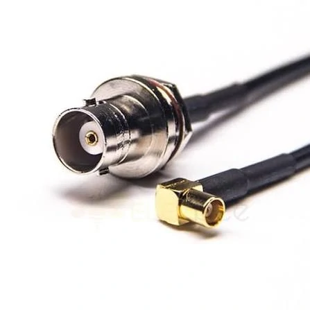
A BNC to SMA coaxial cable assembly designed to connect RF instruments, wireless modules, and antenna systems with different connector interfaces.
An adapter that works on a laboratory bench may not be the right choice for a permanent installation. The difference usually comes down to how the equipment is used, how often the connection is handled, and what happens to the cable after installation.
BNC and RP-SMA interfaces can be found in quite different environments. One may be installed on a measurement instrument, while the other is fitted to a compact wireless module. Connecting them is relatively straightforward once the interface details have been established.
Connecting RF Instruments to Wireless Modules
A common situation occurs during prototype development. An engineer has a signal generator with a BNC output but needs to feed a test signal into a wireless module fitted with an RP-SMA port.
Rather than ordering a completely new cable, an adapter can be installed between the existing coaxial lead and the module.
There is a catch, though. The signal arriving at the module is affected by the entire connection path, not just the adapter. Cable length, connector condition, operating frequency and impedance all contribute to the result.
A setup that produces acceptable readings at 2.4 GHz should not automatically be approved for a 5 GHz test. The components may look identical, but their electrical behavior needs to be checked at the actual operating frequency.
Working With Wi-Fi Equipment and External Antennas
RP-SMA connectors are frequently encountered on wireless routers, access points and other equipment with removable antennas.
During troubleshooting, technicians sometimes need to connect an existing RF test cable to the antenna port. A BNC-to-RP-SMA adapter can make this possible without changing the equipment’s original connector.
The antenna itself should not be overlooked. A connection that fits does not establish that the antenna is suitable for the test. Its frequency coverage, nominal impedance and electrical characteristics still need to match the application.
For instance, an antenna intended for 2.4 GHz operation is not automatically suitable for a 5.8 GHz test simply because an RP-SMA adapter allows it to be connected.
Reusing Existing Cables in Equipment Integration
Replacing an installed cable can be inconvenient, especially inside a control cabinet or an established test fixture.
I would first check whether the existing cable can remain in service. If its impedance, condition and electrical rating are suitable, changing only the connector interface may be a more economical approach.
However, adding adapters at several points is not a good substitute for a properly specified assembly. Every additional mating interface introduces another potential source of mismatch, contact problems and mechanical wear.
For equipment that will remain connected for extended periods, a custom coaxial jumper may deserve consideration.
What Electrical Specifications Should Be Checked Before Connecting the Adapter?
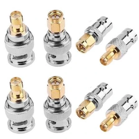
A selection of BNC to SMA RF coaxial adapters with different connector configurations and finishes, suitable for laboratory testing, antenna connections, and wireless equipment integration.
A mechanically compatible connection can still produce disappointing RF results. This is particularly noticeable when equipment operating at different frequencies is connected through an assembly that was never specified as a complete system.
Check the 50-Ohm and 75-Ohm Difference
The first thing I would confirm is impedance.
SMA and RP-SMA interfaces used in conventional wireless RF applications are generally 50 Ω. BNC connectors, however, are manufactured in both 50 Ω and 75 Ω versions.
These versions are not simply different labels applied to the same component. Their internal dimensions and electrical characteristics differ.
| Component | Specification to confirm |
| BNC interface | 50 Ω or 75 Ω |
| Coaxial cable | Nominal impedance |
| SMA/RP-SMA interface | 50 Ω where required |
| RF instrument | Input or output impedance |
| Antenna | Nominal feed impedance |
A 50 Ω BNC connector does not make an entire assembly 50 Ω if the cable behind it is 75 Ω. The same applies in reverse.
This is particularly relevant to measurement applications. An impedance discontinuity can cause reflected energy, affecting the readings obtained from the connected equipment.
Does the Adapter Support the Operating Frequency?
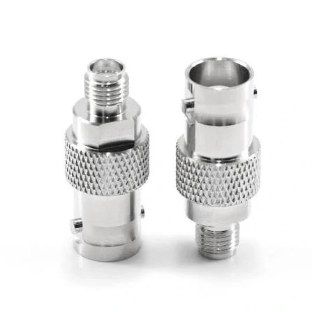
Silver-finished BNC to SMA coaxial adapters designed for secure mechanical connections between compatible RF interfaces in communication and testing applications.
Frequency ratings should be checked against the actual application, not selected simply because a product looks suitable.
A low-frequency adapter may work without obvious problems in a basic continuity test. That tells you very little about its behavior at several gigahertz.
For a 2.4 GHz wireless application, the adapter should have a verified rating that covers the operating band. If the same assembly will be used at 5 GHz or higher, its frequency specification and RF test data should be reviewed again.
The cable can also become the limiting component. A connector rated for a high frequency does not automatically give the completed cable assembly the same capability.
Look Beyond Continuity Test Results
A multimeter can establish whether the center conductor and outer conductor have electrical continuity. It cannot tell you whether the assembly has acceptable RF performance.
For more demanding applications, three measurements are worth requesting:
- VSWR: Shows the degree of impedance mismatch.
- Return loss: Indicates how much incident signal power is reflected.
- Insertion loss: Measures the signal reduction introduced by the component.
A VNA sweep is particularly useful when an adapter will operate close to its specified upper frequency limit.
There is also a testing detail worth keeping in mind: calibration and test cable condition influence the result. Comparing two adapters using different test arrangements may produce misleading conclusions.
Should You Use a Rigid Adapter or a Flexible Coaxial Cable?
I would not make this decision based on price alone. The installation environment is usually a better starting point.
A rigid adapter works well when the two mating interfaces are close together and the connection will remain stationary. It takes up little space and avoids introducing an unnecessary cable section.
The situation changes when the cable needs to bend around an enclosure or when equipment is frequently moved.
| Installation condition | More suitable option | Reason |
| Two closely positioned ports | Rigid adapter | Compact installation |
| Frequently moved equipment | Flexible jumper | Easier cable handling |
| PCB-mounted RF interface | Flexible jumper | Helps reduce direct cable loading |
| Fixed test fixture | Depends on layout | Consider available space |
| Custom cable routing | Coaxial jumper | Length can be specified |
The test frequency should cover the actual application. A result obtained at 1 GHz does not establish performance at 6 GHz.
There is also a practical point about measurement reports: the calibration method, test cables and reference plane should be documented. Otherwise, two laboratories may report different results because their measurement arrangements are not equivalent.
What Information Should Be Included in a BNC-to-SMA Purchase Order?
A purchase order should identify the actual connector configuration, not simply describe the item as an RF adapter.
This becomes especially important when a company buys several similar products for different equipment models. A small difference in center-contact arrangement can make an entire batch unsuitable.
Prepare a Clear Connector Specification
The following example can be used as a starting point for a purchasing request.
Example RF Adapter Purchase Specification
| Item | Required information |
| Product | BNC-to-RP-SMA adapter |
| BNC interface | Specify male or female |
| Device interface | Specify RP-SMA configuration |
| Center contact | Pin or socket |
| Impedance | 50 Ω |
| Frequency | Specify operating band |
| Structure | Straight or right-angle |
| Body material | As specified in drawing |
| Plating | Specify required finish |
| Inspection | Mechanical and electrical |
| Documentation | Approved drawing and test report |
Illustrative specification only. Final dimensions, materials and electrical limits must be confirmed for the actual product.
For custom orders, I would also ask the supplier to confirm whether the proposed configuration is a standard item or requires new tooling or a modified production process.
That distinction can affect MOQ, sample lead time and production consistency.
Request a Sample Before Releasing a Large Order
A product photograph is not a substitute for a physical sample.
Before approving a new supplier, connect the sample to the actual equipment or an approved mating reference. Check the coupling, installation clearance and basic electrical behavior.
For applications with demanding RF requirements, request a test report covering the specified operating band.
Once approved, retain the sample, drawing and inspection criteria together. If the supplier proposes changing the contact material, plating or internal structure later, those changes should be reviewed before the replacement batch is accepted.
What Mistakes Should Buyers Avoid During RF Adapter Sourcing?
Several purchasing mistakes are easy to prevent if the technical information is confirmed early.
| Purchasing mistake | Why it causes problems | Better approach |
| Specifying only BNC-to-SMA | Connector gender remains unclear | Define both ends separately |
| Ignoring reverse polarity | Adapter may not mate with the device | Confirm center-contact arrangement |
| Accepting an unspecified impedance | Electrical mismatch may occur | State 50 Ω or 75 Ω |
| Choosing by appearance | Internal construction may differ | Request drawings and samples |
| Omitting frequency requirements | Unsuitable parts may be substituted | Specify the operating band |
| Changing suppliers without validation | Production characteristics may differ | Requalify replacement samples |
A useful purchasing practice is to maintain a separate part number for every mechanically different configuration. Similar-looking adapters should not share one SKU simply because they belong to the same product family.
FAQ
Is a standard SMA adapter interchangeable with an RP-SMA adapter?
No. Their center-contact arrangements differ. Always verify the equipment-side interface before purchasing, particularly when the adapter is intended for a wireless antenna port.
Does a BNC-to-SMA adapter support 5 GHz applications?
That depends on the specific adapter design and its verified frequency rating.
Can I connect a 75 Ω BNC cable to a 50 Ω RP-SMA device?
For a system designed around 50 Ω, use appropriately matched cables and components whenever possible.
Is a coaxial jumper better than a rigid adapter?
Neither is universally better.