
A cable line can look perfectly normal and still be the wrong fit for the connector.
That happens often with F type connector sourcing. A buyer asks for a “TV coax connector,” the supplier sends a threaded F plug, and the first sample screws onto the port. Then the problem shows up during installation: the cable jacket is too loose in the sleeve, the braid does not sit correctly, the center conductor length is inconsistent, or the connector was made for RG6 while the job still uses RG59.
The F interface is mechanically simple, but the coax path around it is not. In TV, CATV, satellite, CCTV, and cable modem systems, the connector has to match the cable size, the 75 ohm signal path, the installation method, and the environment. A part that is acceptable behind an indoor wall plate may not be the right choice for an outdoor satellite drop or a broadband line feeding a modem.
How Does an F Type Connector Work in a 75 Ohm Coax System?
The F type connector is best known as the threaded connector used on TV, CATV, satellite receivers, wall plates, splitters, and cable modems. Most of these systems are built around 75 ohm coaxial cable. That is the first reason F connectors should not be treated like general-purpose RF adapters.
In many F male plugs, the cable’s own center conductor becomes the center contact. The connector body grips the outer jacket and shield, while the exposed center conductor extends forward into the mating female port. This makes the connector compact and low-cost, but it also makes preparation quality very visible. If the center conductor is too short, the connection may be unstable. If it is too long, it can damage the port or create a poor mechanical fit. If braid strands touch the center conductor, the line can short.
That is why “it screws on” is not a complete inspection standard.
An F connector is only one part of the coax path. Signal behavior also depends on the cable impedance, shielding, splitter quality, adapter count, wall plate condition, and installation method. A cable modem line with several loose connectors and an old splitter may fail even when each individual connector looks acceptable. A satellite run can lose margin because the outdoor connector was not sealed well enough. A CCTV transition can become confusing because the system mixes F, BNC, and RCA-style video hardware.
The useful way to specify an F type connector is to start from the system:
- Is the coax system 75 ohm?
- Is the cable RG6, RG59, or another 75 ohm cable?
- Is the connector male, female, or an F81 coupler?
- Is the termination compression, crimp, or twist-on?
- Is the line indoor, outdoor, behind a wall plate, or inside equipment?
- Will the connector be used with splitters, adapters, or test equipment?
A threaded interface alone does not answer those questions.
F Connectors Are Common in TV, CATV, Satellite, and Cable Modem Lines
F connectors became common because they are practical for high-volume 75 ohm distribution. They are inexpensive, compact, and easy to install on coax cables used in home and building signal systems. Typical applications include cable TV, terrestrial TV antenna feeds, satellite receiver lines, broadband coax, wall plates, splitters, and set-top boxes.
That does not mean every F connector is interchangeable.
Modern broadband and satellite installations usually rely on RG6 because it is better suited to longer runs and higher-frequency distribution than older RG59 in many cases. Older analog video, CCTV, and legacy building wiring may still use RG59. Both may use F-style connectors, but the connector rear body and sleeve must fit the actual cable.
A connector made for RG6 may not grip RG59 correctly. A connector made for standard RG6 may not fit quad-shield RG6 cleanly. A crimp sleeve that is slightly wrong may still look acceptable after crimping, but the braid contact and pull strength may be poor.
For procurement, “F connector for coax cable” is too vague. A better request is:
75 ohm compression F type connector for RG6 coax cable, indoor CATV and cable modem installation.
That one sentence gives the supplier the system impedance, connector family, cable type, termination method, and application.
Do Not Treat Every Threaded TV Connector as the Same Part
The confusing part is that many people use loose names: TV coax connector, cable TV connector, F plug, coax head, antenna connector, or satellite connector. Those names often point to the same general family, but they are not enough for ordering.
The differences usually sit at the rear of the connector, not the threaded front. Buyers should confirm:
| Check Item | Why It Matters | Ordering Risk If Ignored |
| Cable type | RG6 and RG59 have different cable dimensions | Loose fit, poor pull strength, wrong sleeve |
| Shield construction | Standard shield and quad-shield cable may need different connectors | Difficult installation or damaged braid |
| Termination style | Compression, crimp, and twist-on behave differently | Inconsistent installation quality |
| Indoor/outdoor use | Outdoor lines need better sealing and corrosion resistance | Water entry, oxidation, signal drop |
| Male/female/coupler | Interface direction changes the part completely | Wrong mating direction |
| Straight/right-angle | Back-panel space may be limited | Cable bend stress or loose connection |
This is also where adapter decisions should be kept under control. A right-angle F adapter may solve a TV back-panel clearance issue. An F81 barrel coupler may join two F male cable ends. A BNC to F adapter may be useful for CCTV or test transitions. But stacking adapters behind equipment is rarely a clean solution. Each added interface brings another mechanical contact, another possible mismatch, and another troubleshooting point.
How Should You Choose RG6 or RG59 for an F Type Connector?
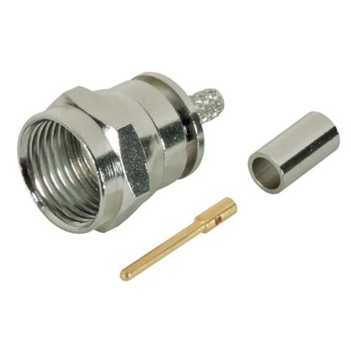
This image shows common F type connectors used with 75 ohm coaxial cables. The connector design must match the cable type, such as RG6 or RG59, to ensure proper mechanical connection and stable signal transmission.
The cable should be chosen before the connector, not after it.
For many current TV, satellite, and broadband coax runs, RG6 is the normal starting point. It is generally preferred for longer building runs because it has better high-frequency behavior than RG59 and is widely used with cable TV and cable modem installations. It is also common in satellite work, where the coax path may include outdoor routing, splitters, grounding hardware, and wall-entry points.
RG59 still appears in older systems, short video links, CCTV installations, and maintenance work where the existing infrastructure already uses RG59. It should not be automatically replaced in the connector description with RG6 just because RG6 is more common today. If the system uses RG59, the F connector must match RG59.
A sourcing mistake happens when the buyer only checks the front thread. The F interface mates, so the part seems correct. During assembly, the rear body tells a different story. The cable jacket may not seat firmly, the sleeve may not compress evenly, or the center conductor extension may vary from piece to piece.
The same issue can happen with RG6 quad-shield cable. Quad-shield cable has additional shielding layers, which can change how the connector fits during preparation and compression. A connector that installs smoothly on standard RG6 may become tight or unreliable on quad-shield RG6 unless it was designed for that cable construction.
Use RG6 F Connectors for Most Modern TV, Satellite, and Broadband Runs
RG6 F connectors are usually the safer choice when the job involves modern cable TV, satellite TV, broadband coax, or longer in-building runs. The cable is widely available, the connector ecosystem is mature, and compression-style RG6 F connectors are common in professional installations.
The important point is to specify the cable construction clearly. “RG6” alone may still be incomplete when the supplier needs to know jacket size, standard shield or quad-shield, indoor or outdoor jacket, and termination style.
For example, a useful requirement could be:
RG6 compression F male connector, 75 ohm, for indoor cable TV and broadband coax, nickel-plated body, compatible with standard RG6 jacket size.
For outdoor satellite or drop cable work, the description should be more specific:
Outdoor RG6 compression F connector, 75 ohm, weather-resistant design, suitable for satellite coax line and exterior cable routing.
This avoids leaving the supplier to guess whether sealing, corrosion resistance, or jacket grip matters.
Keep RG59 F Connectors for Systems That Still Require RG59
RG59 should not be treated as obsolete in every case. Many existing video systems, short patch runs, CCTV installations, and maintenance projects still use it. Replacing only the connector without checking the installed cable can create an avoidable mismatch.
The risk is not just electrical. It is mechanical. RG59 cable is smaller than RG6, so a connector intended for RG6 may not grip correctly. That can lead to a connector that pulls off more easily, loses shield contact, or creates intermittent signal problems after the cable is moved.
For repair work, ask for the actual cable marking or measure the cable outside diameter before ordering. If the customer only says “old TV cable,” do not assume RG6. Check the jacket print, compare the cable diameter, or send a sample photo with caliper measurement.
F Connector Cable Fit Matrix
Use this simple matrix before purchasing or assembling F connectors. It is not a lab test. It is a practical filter to prevent wrong connector selection before samples are ordered.
| Field | Option / Record | Decision Note |
| Cable type | RG6 / RG59 / other 75 ohm coax | Connector rear body must match cable size |
| Impedance | 75 ohm | Keep the full system in the same impedance family |
| Cable OD | mm / inch | Confirm sleeve and jacket grip |
| Shielding | Standard / quad-shield | Quad-shield may need a compatible connector |
| Connector style | Compression / crimp / twist-on | Match tool, cable, and reliability target |
| Interface | F male / F female / F81 coupler / adapter | Prevent wrong mating direction |
| Application | TV / CATV / satellite / cable modem / CCTV | Defines environment and signal expectations |
| Environment | Indoor / outdoor / panel / wall plate | Affects sealing and mechanical stress |
| Final decision | Fit / review / not compatible | Do not approve without cable fit confirmation |
A simple rule works well: if the cable type, cable OD, and termination method are not known, the connector choice is not ready for purchase.
How Do Compression and Crimp F Connectors Compare?
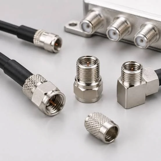
This image shows compression-style F connectors designed for RG6 coaxial cable. Compression termination provides strong cable retention, consistent shielding contact and improved installation reliability.
The termination method decides how well the connector holds the cable, not just how neat the finished part looks.
A compression F connector uses a compression tool to press the connector body around the cable jacket and shield. The result is usually more repeatable than a hand-tightened or poorly matched crimp part. This is why compression connectors are common in professional CATV, satellite, and broadband coax work. They are especially useful where the cable may be pulled, bent, routed outdoors, or connected to a modem line that needs stable signal behavior.
Crimp F connectors are still used in controlled assembly work. They can perform well if the crimp sleeve, crimp die, and cable diameter match. The problem starts when a buyer treats “crimp F connector” as one universal item. A wrong ferrule size may still close under the tool, but the shield contact can be weak or uneven. The connector may pass a quick visual check and fail later during a pull test or field installation.
Twist-on F connectors are the least controlled option. They are easy to install without special tooling, but they depend heavily on cable preparation and hand force. For temporary, simple, or low-risk use, they may be acceptable. For cable modem, satellite, outdoor, or production assembly work, they create too much variation.
The table below is a practical scorecard for sourcing and production teams. It is not a claim that one method is always best. It shows where each method usually fits.
| Termination Method | Tool Needed | Pull Strength | Outdoor Seal | Repeatability | Best Use |
| Compression | Compression tool | High | Good when connector is outdoor-rated | High | CATV, satellite, cable modem, professional installation |
| Crimp | Crimp tool and matched die | Medium to high | Depends on connector design | Medium | Controlled assembly, indoor coax, repair work |
| Twist-on | No special tool | Low to medium | Poor to medium | Low | Temporary use, simple indoor repair |
Compression usually wins when the installation has to survive handling. Crimp can still be the correct answer when a workshop has the right tooling and inspection control. Twist-on should be treated as a convenience part, not a production standard.
Check the Tool Before Blaming the Connector
A poor termination is not always caused by a bad connector.
The crimp die may be wrong. The cable may be stripped too deeply. The braid may fold unevenly. The center conductor may be cut too short. In some cases, the connector is technically correct, but the operator uses the wrong preparation length from another cable family.
A clean F connector installation should show:
- firm jacket grip
- no loose sleeve movement
- no braid touching the center conductor
- consistent center conductor extension
- no cracked dielectric
- no visible corrosion or plating damage
- no spinning connector body after termination
For large cable assembly orders, do not rely only on a product photo. Ask for the cable type, connector drawing, recommended strip length, tool model, and inspection method. A small detail such as ferrule size can separate a stable coax assembly from a batch of connectors that fail during installation.
How Do You Identify F Male, F Female, and F81 Connectors?
This image displays different coaxial connector interfaces and adapter structures. F connector adapters should be selected according to connector type, impedance, frequency requirements and application environment.
F connector gender can confuse buyers because the cable’s center conductor often acts as the male contact.
An F male connector is usually the cable-end plug. It has the threaded nut and the center conductor extends forward into the equipment port. This is the connector commonly found at the end of RG6 or RG59 TV coax cable.
An F female connector is usually found on equipment, wall plates, splitters, adapters, and panel feedthrough parts. It receives the male cable plug. A TV input, cable modem port, satellite receiver input, splitter port, or wall plate outlet will often use an F female interface.
An F81 connector is a barrel coupler. Most F81 couplers are F female to F female, used to join two F male cable ends in an inline connection. It is a simple part, but it still adds another contact point. In a clean installation, one coupler is acceptable when needed. Several couplers in a row usually mean the cable length or routing plan should be corrected.
Use this quick identification method:
| Part Name | Common Location | Visual Clue | Typical Use |
| F male connector | Cable end | Threaded rotating nut, center conductor protrudes | Connect RG6/RG59 cable to equipment or splitter |
| F female connector | TV, modem, wall plate, splitter, adapter | External threaded port with internal contact | Receives F male plug |
| F81 coupler | Inline cable joint or panel feedthrough | Female interface on both sides | Joins two F male cable ends |
| Right-angle F adapter | Tight equipment space | 90-degree body | Reduces cable bend behind TV or cabinet |
| F panel connector | Enclosure or wall plate | Mounting nut or panel structure | Passes coax through a panel |
For ordering, avoid short requests such as “F head” or “TV plug.” Write the actual direction. For example: “F male compression connector for RG6 cable” or “F female to F female F81 barrel coupler, 75 ohm.”
That wording removes most of the confusion before quotation.
Which F Connector Adapter Solves Your Interface Transition?
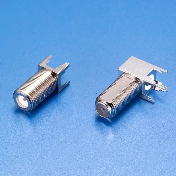
The F81 barrel coupler features female-to-female F interfaces and is designed for connecting two 75 ohm coaxial cables. It is commonly used for cable extension, wall plate connections and coax signal distribution.
Adapters should solve a specific interface problem. They should not become a habit.
A straight F female to F female coupler joins two F male cable ends. A right-angle F adapter helps behind a wall-mounted TV or a shallow cabinet. A panel feedthrough allows the coax line to pass through a metal panel or enclosure. A BNC to F connector links an F-type coax cable to equipment that uses a BNC interface, often in video, CCTV, or test environments.
The dangerous area is mixed impedance and unclear application.
F connectors are normally associated with 75 ohm TV, CATV, satellite, and broadband coax systems. BNC connectors may be used in both 50 ohm and 75 ohm versions, depending on the application. If a user connects a 75 ohm F cable into a 50 ohm RF test system through a random BNC adapter, the mechanical connection may work, but the RF result may not represent the actual system correctly.
SMA and N type transitions need even more caution. SMA is common in compact RF modules, antennas, Wi-Fi devices, GPS devices, and test leads. N type is common in larger RF systems, outdoor antenna feeds, and higher-power equipment. An F adapter does not convert the application category. It only changes the mechanical interface.
A useful adapter decision table looks like this:
| Transition Need | Possible Part | Main Check Before Use | Risk Level |
| Join two F male cable ends | F81 coupler | Cable condition and insertion loss budget | Low |
| Fit cable behind wall-mounted TV | Right-angle F adapter | Bend relief and port stress | Low to medium |
| Pass coax through panel | F female bulkhead or feedthrough | Panel thickness and grounding | Medium |
| Connect F cable to BNC equipment | BNC to F adapter | 50 ohm vs 75 ohm, video vs RF test | Medium to high |
| Connect TV coax into RF module path | F to SMA adapter | System impedance and frequency plan | High |
| Extend several short cables | Multiple F couplers | Total adapter count and signal margin | Medium to high |
Adapter stacking is a quiet source of trouble. One adapter may be fine. Three adapters behind a TV, modem, or test fixture can add mechanical leverage, loosen the connector, increase return loss, and make troubleshooting slower. If the installation needs multiple adapters, a custom coax cable assembly with the correct end interfaces is often cleaner.
How Does 75 Ohm Impedance Affect F Connector Selection?
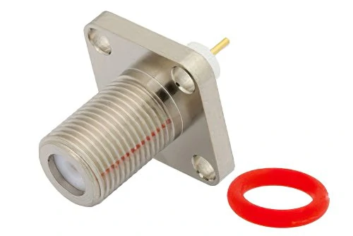
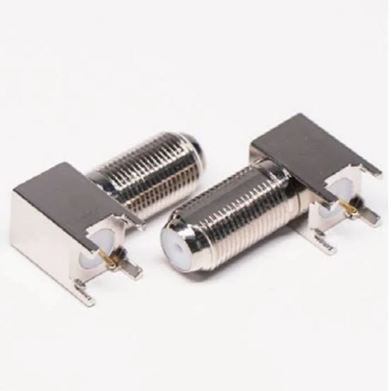
This image shows a panel mount F type connector designed for 75 ohm coaxial systems. These connectors are commonly used in equipment enclosures, wall plates and custom coax cable assemblies.
The F connector family belongs mainly to 75 ohm coax systems. That includes TV distribution, cable TV, satellite receiver lines, CCTV/video paths, and cable modem connections.
The connector does not work alone. The cable, splitter, wall plate, coupler, adapter, and equipment port should stay in the same impedance system. If the line is designed as a 75 ohm path, the connector should not be randomly mixed with 50 ohm RF components just because the thread or adapter fits.
Impedance mismatch can show up as reflections, degraded return loss, unstable modem behavior, or poor signal quality after splitters and wall plates. In video systems, symptoms may look like noise, dropouts, or inconsistent performance after the cable is moved. In broadband coax, symptoms can be harder to trace because the connector may be only one weak point among splitters, old cables, and poor wall outlets.
A continuity test cannot confirm this behavior. Continuity only tells you that the center conductor and shield are connected where they should be, and not shorted where they should not be. It does not prove that the coax line behaves correctly at the operating frequency.
For basic installation work, start with visual and continuity checks. For sensitive broadband, lab, or production work, use signal quality checks or RF measurement where appropriate.
A practical rule for buyers:
If the system is TV, CATV, satellite, or cable modem coax, specify 75 ohm cable, 75 ohm connector hardware, and the exact cable type before selecting adapters.
That single rule prevents many wrong substitutions.
How Should You Select F Connectors for TV, CATV, and Satellite Use?
The same F connector family appears in several systems, but the installation conditions are not the same.
A connector behind an indoor TV usually deals with clearance, cable bend, and repeated movement during setup. A connector on a satellite line may face outdoor exposure, moisture, UV aging, and pull stress. A cable modem line may look simple, but poor connector fit can create intermittent signal problems that are hard to diagnose later.
For TV wall plates and back-panel connections, space is often the first problem. The cable may leave the connector at a sharp angle because the TV is mounted close to the wall. In that case, a right-angle F adapter can reduce cable strain. Still, the adapter should be used intentionally. If the cable is already too stiff or too short, a better-length cable assembly may be cleaner than forcing several adapters into a tight space.
For CATV and broadband coax, keep the connection path short, tight, and easy to inspect. Splitters, F81 couplers, wall plates, and old cable sections can all add uncertainty. A modem line that works one day and drops the next may not have one dramatic failure point. It may have a slightly loose connector, a poor shield contact, an oxidized outdoor fitting, and an unnecessary adapter stack.
Satellite coax runs need more attention to sealing and cable strain. Outdoor connectors should be selected for the environment, not only for the cable type. Water entry and corrosion can create slow failures that do not appear during the first installation check.
| Application | Common Cable | Connector Focus | Common Risk |
| Indoor TV | RG6 or RG59 | Clearance, bend relief, correct male/female interface | Loose connector behind cabinet or wall mount |
| CATV line | RG6 | Stable compression termination, low adapter count | Poor shield contact or old splitter |
| Cable modem | RG6 | Clean 75 ohm path, tight fittings, good wall plate | Intermittent broadband signal issues |
| Satellite receiver | RG6 | Outdoor-rated connector, sealing, corrosion resistance | Moisture entry and cable pull stress |
| CCTV/video | RG59 or RG6 | Correct video impedance and adapter direction | Mixing BNC/F parts without checking system type |
The connector choice should follow the route. Indoor, outdoor, wall plate, panel, splitter, and modem paths do not create the same mechanical risk.
How Do F Connectors Compare With BNC, SMA, and N Type?
F connectors are not a weaker version of BNC, SMA, or N Type. They belong to a different use case.
F is mainly used in 75 ohm TV, CATV, satellite, and broadband coax systems. BNC is common in video, lab equipment, CCTV, and some RF test setups. SMA is common in compact RF modules, antennas, GPS, Wi-Fi, LTE, and instrument leads. N Type is larger and often used for outdoor antenna feeds, higher-power RF paths, and larger coax cables.
The mistake is to treat adapters as if they make these systems equivalent. A BNC to F connector can be useful. An F to SMA adapter may solve a temporary interface problem. But the adapter does not change the cable impedance, cable loss, operating frequency, power level, or the reason the original connector was selected.
| Connector Family | Common System | Typical Impedance | Where It Fits Better Than F |
| F Type | TV, CATV, satellite, cable modem | 75 ohm | Best fit for threaded 75 ohm coax distribution |
| BNC | Video, CCTV, instruments, RF test | 50 or 75 ohm versions | Faster connect/disconnect and lab/video equipment |
| SMA | RF modules, antennas, compact devices | Usually 50 ohm | Higher-frequency compact RF connections |
| N Type | Outdoor RF, antenna feed, larger coax | Usually 50 ohm, some 75 ohm versions | Larger cable, outdoor RF, higher power handling |
A buyer should not write “F to SMA adapter” without describing the signal path. The supplier still needs to know whether this is a 75 ohm video/broadband transition, a temporary bench setup, or a real RF product interface. Those are different risks.
How Can You Test an F Connector Installation Before Use?
Start with the simple checks. Many F connector failures are visible before any instrument is connected.
Look at the center conductor length. It should extend far enough to make contact, but not so far that it damages the mating port. Check that the dielectric is not crushed or cracked. Make sure no braid strand is touching the center conductor. Confirm the connector sleeve is seated firmly and does not spin or slide after termination.
Then check electrical basics:
- center conductor continuity
- shield continuity
- no short between center and shield
- stable contact after light cable movement
- no obvious oxidation or contamination
These checks do not prove RF performance, but they catch many assembly mistakes.
For production cable assemblies or field work with repeated complaints, add a pull check and signal check. In broadband coax, modem signal readings or a proper signal meter may be more useful than only checking continuity. In workshop inspection, a documented acceptance sheet helps keep operators from relying on appearance alone.
F Connector Installation Acceptance Sheet
Use this as a practical inspection record before releasing cable assemblies or accepting installed lines.
| Inspection Item | Pass / Fail | Notes |
| Cable type confirmed | RG6, RG59, or other 75 ohm cable | |
| Connector style confirmed | Compression, crimp, or other | |
| Center conductor length | Not too short, not excessive | |
| Shield trim | No loose braid touching center | |
| Connector seating | Sleeve/body fully seated | |
| Pull test | No movement under light pull | |
| Indoor/outdoor seal | Required only where applicable | |
| Continuity check | Center and shield verified | |
| Short check | No center-to-shield short | |
| Signal check | TV, modem, satellite, or meter result | |
| Final result | Accept or rework |
A failed pull test should not be ignored just because the signal works at that moment. Movement during installation, shipping, or customer use can turn a weak termination into an intermittent fault.
How Do You Specify the Right F Type Connector for Ordering?
Good ordering language prevents most F connector mistakes.
A vague request like “TV coax head” forces the supplier to guess. That guess may be wrong on cable size, male/female direction, sleeve type, weather rating, or adapter style. A better request includes the cable, impedance, connector style, application, and environment.
Use this format:
75 ohm compression F male connector for RG6 coax cable, indoor CATV and cable modem use, compatible with standard RG6 jacket size.
For a coupler:
75 ohm F81 female-to-female barrel coupler for joining two F male RG6 cable ends in an indoor wall plate installation.
For an adapter:
75 ohm BNC female to F female adapter for CCTV/video transition, confirm impedance compatibility before shipment.
For outdoor satellite work:
Outdoor-rated 75 ohm compression F connector for RG6 satellite coax, weather-resistant body, suitable for exterior cable routing.
The goal is not longer wording. The goal is fewer assumptions.
Before quotation, confirm:
- cable type and cable OD
- 75 ohm system requirement
- male, female, coupler, or adapter
- compression or crimp termination
- straight, right-angle, or panel/feedthrough structure
- indoor or outdoor use
- plating and corrosion requirement
- quantity and packaging label
- inspection requirement, if production consistency matters
If the cable assembly will be used in a sensitive broadband, video, or RF transition path, send the cable type, operating system, connector count, adapter count, and installation environment before ordering. That information makes the quotation slower by a few minutes, but it can prevent the wrong batch.
FAQ
Is an F type connector the same as a TV coax connector?
Many TV coax cables use an F type connector, so the terms are often used together. For ordering, they should not be treated as identical. “TV coax connector” describes the application. “F type connector” describes the interface family. You still need to confirm RG6 or RG59 cable, 75 ohm impedance, male or female interface, and compression or crimp termination.
Can I use an RG6 F connector on RG59 cable?
Usually, no. RG6 and RG59 have different cable dimensions. An RG6 connector may screw onto the equipment port, but the rear body may not grip RG59 cable correctly. That can cause weak pull strength, poor shield contact, or unstable signal behavior. Match the connector to the actual cable type and outside diameter.
Is a compression F connector better than a crimp F connector?
For professional CATV, satellite, outdoor, and cable modem installations, compression F connectors are usually more repeatable and better sealed when the correct tool is used. Crimp F connectors can still work well in controlled assembly, but the crimp die, ferrule size, and cable must match. A bad crimp can look acceptable and still fail later.
What is an F81 connector used for?
An F81 connector is usually a female-to-female barrel coupler. It joins two F male coax cable ends in an inline connection. It is common in wall plates, cable extensions, and simple repair work. It should be used only where needed, because each extra coupler adds another contact point in the coax path.
Can I connect a BNC device to an F type cable?
Yes, a BNC to F connector or adapter can make the mechanical transition. The system still needs to be checked. BNC parts may be 50 ohm or 75 ohm, while F type cable systems are usually 75 ohm. For CCTV and video work, this may be normal. For RF test setups, confirm impedance and frequency before relying on the result.
Why did my TV or modem signal drop after changing an F connector?
Common causes include incorrect center conductor length, loose compression, braid touching the center conductor, poor shield contact, RG6/RG59 mismatch, too many adapters, a bad splitter, or water damage on an outdoor fitting. Check the full coax path, not only the connector you replaced.
Should I use an F connector coupler or order a new cable assembly?
A coupler is fine for a simple short extension or repair. If the path already has several adapters, tight bends, signal complaints, or poor access behind equipment, a new cable assembly with the correct length and end interfaces is usually cleaner. Fewer joints usually means easier installation and easier troubleshooting.
Final Buying Note
An F type connector is easy to recognize, but it is not complete until the cable and system are known.
For TV, CATV, satellite, cable modem, and CCTV/video work, start with the 75 ohm coax path. Confirm RG6 or RG59, cable OD, shielding, connector gender, termination method, adapter count, and indoor or outdoor use. Then select the connector.
For TEJTE sourcing or custom cable assembly requests, send the cable type, connector direction, quantity, application, and inspection requirement. A short but complete specification helps avoid the most common F connector problems: wrong cable fit, weak termination, unnecessary adapters, and unclear impedance transitions.
