
The cable is marked RG6. The connector bag is also marked RG6. Yet the connector stops halfway onto the cable, or it compresses with a sleeve that still feels loose.
That is not unusual.
“RG6” is not enough information to approve an F type connector for production. A field installer may only need one cable end to work. A buyer ordering several thousand pieces has a different problem: the connector, cable construction, preparation dimensions, and installation tool all need to behave as one repeatable combination.
Before stripping the first cable, confirm two things. First, make sure the device actually uses an F-Type interface. Second, measure the actual coax construction rather than assuming every cable carrying the RG6 name will fit the same connector body.
Those two checks prevent a surprising number of installation problems later.
How do you confirm the coax really needs an F type connector?
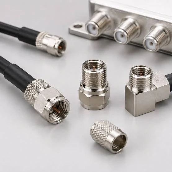
Collection of F-Type coax connectors, straight and right-angle adapters, cable-mounted connectors and equipment-side jacks used in 75-ohm coaxial installations.
Do not start with the cable name. Start at the equipment.
A technician may see RG6 running toward a television, modem, receiver, amplifier, splitter, or wall plate and immediately reach for an F connector. That may be correct, but the cable family alone does not define the interface at the other end.
Identify the device port before cutting the cable
Inspect the actual port or the equipment drawing first.
For a typical installation, record the interface on each device that the cable must connect to. Common equipment may include:
- cable modems;
- satellite receivers;
- TVs and set-top boxes;
- splitters;
- wall plates;
- distribution amplifiers.
A threaded coax port is a useful visual clue, but visual similarity is not an engineering specification. Check the port family, gender, impedance requirement, and available installation space before preparing the cable.
This matters even more in replacement work. An installer may be looking at a cable left from an older system while the new equipment uses a different port arrangement.
Separate the cable-side plug from the equipment-side jack
For many F-Type cable runs, the connection can be written simply as:
Coax cable → male cable connector → female equipment port
That short line is worth putting on the work instruction or RFQ.
It prevents terminology from drifting between the buyer, cable assembler, and installer. “F connector,” “F type coax connector,” and “coax F connector” may all appear in a purchasing conversation, but the supplier still needs to know which side is cable-mounted and which interface is already built into the equipment.
Gender errors are especially easy to miss when an RFQ contains only a product photo.
A more useful BOM note would look like this:
RG6 coax cable + cable-mounted male F-Type connector, 75-ohm system, termination method to be confirmed against actual cable dimensions and approved tooling.
That gives the supplier considerably more information than “F connector for TV cable.”
Keep F-Type separate from push-in TV connectors
Threaded F-Type hardware should also be kept separate from push-fit television connector families during identification.
They may appear in related TV and coax installations, but the mating method is different. If the device uses a push-fit TV/PAL-style interface, installing a male F connector on the cable does not solve the interface mismatch by itself.
For a broader connector-family comparison, this is a natural place to internally link to compare F-Type with TV/PAL connectors rather than repeating that entire topic here. The article outline specifically keeps this guide focused on F-Type installation and RG6 fit instead of turning it into another connector encyclopedia.
Complete an endpoint identification card
For installations involving several device types, do not leave interface identification in chat messages or memory. Record it.
This F-Type Endpoint Verification Card is particularly useful when a purchasing team is sourcing connectors for equipment located at another site. One clear port photo and a completed card can prevent samples being produced around the wrong interface assumption.
Which RG6 dimensions must match the connector body?
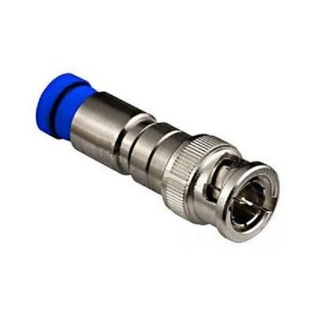
Example of a compression-style BNC male coax connector with a rear cable sleeve, illustrating a coax termination design that requires compatible cable dimensions and tooling.
The next sourcing trap appears after the interface has been confirmed.
Two cables can both be sold as RG6 and still require a closer fit check before one connector is approved for both. The useful question is not simply, “Is this an RG6 F connector?” It is, “Does this connector body fit the construction and dimensions of this specific RG6 cable?”
Match actual cable construction rather than “RG6” alone
At minimum, check the dimensions that affect how the cable enters and seats inside the connector:
- jacket outside diameter;
- shield or braid diameter;
- dielectric diameter;
- center-conductor diameter;
- dual-, tri-, or quad-shield construction.
The rear sleeve has to accept the prepared cable. The dielectric has to reach the intended internal position. The shield has to be prepared without creating an uncontrolled mass of braid under the body.
If one of those relationships is wrong, changing the compression tool will not magically turn an incompatible connector into the correct part.
For background on RG6 as a cable family, an internal link to the RG cable guide is more useful than repeating general RG6 theory here. This installation guide should stay focused on connector fit. That separation is part of the planned article structure.
Check shield count before selecting the sleeve
Shield construction deserves its own line on the drawing or BOM.
A dual-shield RG6 and a quad-shield RG6 may not present the same rear termination geometry after preparation. Additional foil and braid layers can change how the cable enters the connector and how much material must be managed around the rear sleeve.
Watch for four practical symptoms during the first sample:
- unusually high insertion force;
- braid bunching at the connector entrance;
- cable stopping before full seating;
- a rear sleeve that remains loose after the expected installation cycle.
Do not solve those symptoms by forcing the cable deeper. First verify that the connector was specified for the actual cable construction.
Measure before approving a substitute cable
Substitution is where a working assembly can quietly become a production problem.
Suppose the approved cable becomes unavailable. Purchasing finds another cable marked:
RG6 / 75 Ω
That is a starting point, not automatic approval.
Before releasing the replacement cable, compare the physical construction against the connector already on the BOM. If jacket OD, shield package, dielectric size, or center conductor changes enough to affect termination, the connector and tool combination should be checked again.
This is why a supplier-ready specification should identify the cable manufacturer and part number whenever possible, not only the RG family.
Build a cable-to-connector fit record
A simple fit matrix gives production, purchasing, and QC one approved reference instead of relying on the wording printed on a connector bag.
Do this on the first approved cable-and-connector combination, then repeat the check whenever either part number changes.
The goal is not to measure every production piece with a caliper. It is to stop an unverified substitution from entering production simply because both packages happen to say “RG6.”
Choose compression only after checking the cable geometry
Compression is often the preferred termination method for RG6 installations where repeatability, retention, and production consistency matter.
But “compression” is not a compatibility guarantee.
A compression F connector that works well on one RG6 construction may not seat correctly on another. The connector body, rear sleeve, cable preparation, and compression stroke all have to match.
Use compression when repeatable installation and retention matter
Compression termination is useful when the same assembly process needs to be repeated across many cable ends.
Compared with a casual field repair, production work usually cares more about:
- consistent insertion depth;
- repeatable finished dimensions;
- pull retention;
- controlled cable preparation;
- predictable inspection;
- faster operator training.
That makes a F type compression connector attractive for production, broadband installation, satellite cabling, and structured coax work.
The risk appears when purchasing treats every “RG6 compression connector” as interchangeable.
A connector can have the correct front F-Type interface and still have the wrong rear geometry for the cable.
Keep compression, crimp, and twist-on as separate process choices
These are not simply cosmetic versions of the same termination.
They create different production requirements.
| Requirement | Compression | Crimp | Twist-On |
| Dedicated tool | Yes | Yes | Usually no |
| Repeatability | High when approved | High when controlled | Operator-dependent |
| Cable-size sensitivity | High | High | Moderate to high |
| Pull retention | Generally strong | Depends on ferrule/crimp | More variable |
| Outdoor potential | Depends on full design | Depends on sealing | Usually limited |
| Production suitability | Strong | Strong | Limited |
| Field repair | Good with tooling | Possible | Convenient |
| Main risk | Wrong stroke/body fit | Wrong die/ferrule | Inconsistent installation |
Compression is not automatically “better” in every installation.
A properly specified crimp termination can be suitable for controlled production. Twist-on hardware can solve a temporary field problem. The process should be selected around the actual installation, retention requirement, environment, and tooling available.
The practical mistake is approving one method and then allowing operators to substitute another because the front connector looks the same.
Reject a compression body that does not seat the cable fully
Before operating the tool, inspect the cable position.
Warning signs include:
- cable stops short of the internal reference;
- rear sleeve will not accept the prepared jacket;
- jacket bunches during insertion;
- braid folds into an uncontrolled lump;
- dielectric does not reach the intended internal stop.
Do not use extra force as a process correction.
If the connector only works when one operator pushes unusually hard, the cable-to-connector combination should be rechecked.
How should the center conductor be prepared and projected?

An RG6 coax cable and compression connector prepared for assembly, showing the cable jacket, braid, dielectric and center conductor before installation.
The F-Type interface has an unusual feature compared with many RF connector families:
thecoaxial cable center conductor itself serves as the male center contact.
That means cable preparation is not only a termination operation. It directly creates part of the mating interface.
Control strip length from one reference surface
A work instruction should define the finished cable end from a consistent mechanical reference.
Important dimensions include:
- jacket strip length;
- shield fold-back or preparation length;
- dielectric exposure;
- final center-conductor projection.
Avoid instructions such as “leave a little center wire showing.”
That wording may work for a one-off repair. It is not suitable for a production process.
A better drawing assigns dimensions.
| Dimension | Symbol | Nominal | Tolerance | Inspection |
| Cable insertion depth | A | Project-specific | Drawing | Gauge / visual |
| Exposed conductor | B | Project-specific | Drawing | Caliper / gauge |
| Sleeve position | C | Project-specific | Process limit | Visual |
| Dielectric position | D | Project-specific | Drawing | Visual |
| Overall connector length | E | Project-specific | Drawing | Caliper |
This F Connector Finished-End Dimension Sheet also gives purchasing something concrete to request when comparing alternative connector suppliers.
Avoid both excessive and insufficient projection
Too much exposed conductor can create mechanical problems.
Possible consequences include:
- interference during mating;
- bending of the conductor;
- damage to the equipment-side contact;
- increased shorting risk if the conductor is distorted.
Too little projection creates a different failure mode.
The connector may thread onto the equipment normally while the electrical contact remains marginal.
Symptoms may include:
- intermittent signal;
- movement-sensitive operation;
- unexpected signal loss;
- poor mating consistency between different device ports.
This is why continuity alone should not be used to approve the final installation.
A center conductor can be electrically continuous and still be mechanically wrong for the mating interface.
Keep the conductor condition under inspection
The exposed conductor should also be checked for:
- nicks from stripping;
- bending;
- oxidation;
- flattened surfaces;
- contamination;
- dielectric damage around the conductor.
If the cable conductor becomes the contact, damage introduced during stripping becomes connector damage.
Which F connector tool belongs to the selected connector?
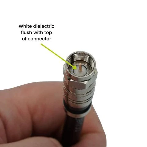
Close-up inspection of an installed RG6 F connector showing the dielectric position and exposed center conductor for cable seating and termination verification.
The next mistake happens after the cable and connector are correct.
The operator reaches for a tool marked “RG6.”
That label is not enough.
Match the compression tool to connector stroke and body design
An F connector tool must close the selected connector to the intended finished position.
The relevant combination is:
Cable P/N + connector P/N + preparation method + compression tool + tool setting
Changing any one of those should trigger at least a first-piece check.
A tool may physically accept the connector while using the wrong compression stroke.
That can produce an assembly that looks finished but has poor retention or incomplete sleeve compression.
Separate cable-preparation tools from compression tools
One termination may require several different tools:
- cable cutter;
- coax stripper;
- preparation tool;
- compression tool;
- dimensional gauge.
Do not treat them as one generic “F connector tool.”
A good compression cycle cannot correct a poor strip.
Likewise, a perfect strip does not compensate for the wrong compression stroke.
Verify the setup before production starts
Before releasing the process, confirm:
- compression stroke;
- connector seating;
- tool jaw condition;
- full-cycle operation;
- connector-specific adapter or anvil, if required;
- finished compression length.
For production buyers, this record is more useful than asking a supplier only whether they “have an RG6 compression tool.”
How do you preserve a 75-ohm path through the termination?
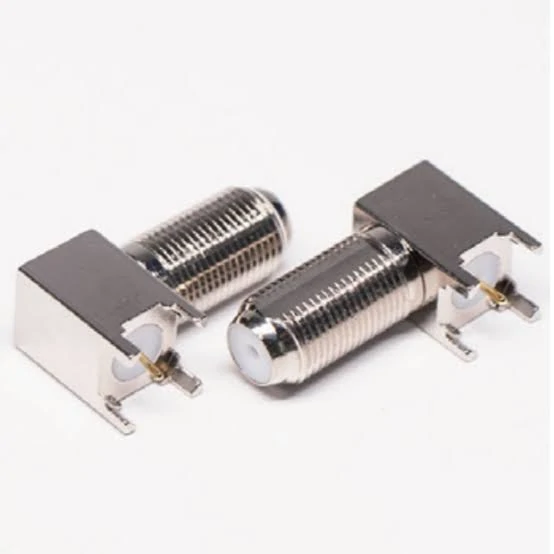
Two right-angle PCB-mounted F female connectors featuring threaded coaxial interfaces for televisions, receivers, amplifiers and other 75-ohm RF equipment.
A mechanically successful termination can still be the wrong RF connection.
F-Type systems are commonly built around a 75-ohm path, so the connector should not be considered in isolation.
The full chain may look like:
75Ω source → F connector → RG6 → splitter or coupler → F connector → receiver
Every element should match the intended system impedance.
Keep cable, connector, device, and passive hardware consistent
A 75 ohm F connector does not correct an incorrect cable or passive component elsewhere in the path.
Check:
- equipment port impedance;
- connector specification;
- RG6 cable specification;
- splitter or coupler specification;
- receiver/load requirement.
This sounds basic, but substitution often enters the system through passive hardware rather than the main cable.
A replacement splitter, wall plate, or coupler may be selected because it mates mechanically while its RF specification is never reviewed.
Avoid disturbing the dielectric more than the connector design allows
Near the termination, RF geometry depends on more than the threaded interface.
The condition of the:
- dielectric;
- braid;
- shield transition;
- center conductor;
- cable seating
can affect the actual transition.
Do not crush, stretch, cut back, or reshape the dielectric simply to make a poorly fitting connector install.
The mechanical geometry is part of the RF path.
Use IEC 61169-24 as the interface baseline
For formal interface and inspection work, IEC 61169-24:2019 is the relevant sectional specification identified in the article plan for Type F screw-coupling RF connectors used in typical 75Ω cable networks.
The standard covers interface dimensions, gauging, mandatory tests, and inspection requirements, and the outline uses it as the technical baseline for this guide rather than inventing universal installation dimensions.
That distinction matters.
A blog article can explain what to inspect. The actual connector drawing, project specification, and applicable standard should define the acceptance limit.
This does not replace RF testing.
It prevents a more basic sourcing error: building a mechanically compatible cable run from parts that were never checked as one electrical system.
How much thread engagement does the device side actually need?
An F connector can feel tight and still be poorly mated.
Finger-tightness tells you that resistance has increased. It does not tell you whether the nut started cleanly, whether enough thread is engaged, or whether the center conductor entered the device contact correctly.
Inspect the mating thread instead of judging by feel
During first-piece inspection, check:
- smooth thread engagement;
- free nut movement before final seating;
- no cross-threading;
- no visible damage to the device jack;
- correct connector seating;
- stable cable alignment after mating.
Cross-threading is particularly easy to introduce when the cable approaches a recessed port at an angle.
Once the thread has been damaged, additional wrench force usually makes the situation worse rather than improving the RF connection.
Keep wrench use within the actual installation requirement
There is no useful universal rule that every F-Type connection should be tightened as hard as possible.
The correct installation force depends on the specific connector, equipment port, and project requirement.
For production equipment or controlled assemblies, use the connector or device specification where a torque requirement is given. For general installations, the priority is proper thread engagement and full seating without damaging the port.
Check clearance around recessed ports
Mechanical clearance often becomes the real limitation behind:
- wall-mounted TVs;
- recessed modem ports;
- closely spaced splitter outputs;
- deep wall plates;
- equipment mounted near enclosure walls.
A connector that works on an open bench may become difficult to install after the equipment is mounted.
A useful acceptance checklist is simple:
- thread starts smoothly;
- nut reaches full seating;
- no cross-threading;
- center conductor enters correctly;
- adjacent ports remain accessible;
- cable does not force the connector sideways;
- final connection remains mechanically stable.
Decide when straight, right-angle, or coupler hardware is actually needed
Adding another adapter can solve a mechanical problem.
It also adds another interface.
Keep a straight connection when clearance allows
A direct cable-to-device connection has fewer contact points and fewer troubleshooting variables.
If the cable can reach the port without an excessive bend, there is usually little reason to add more hardware.
Use right-angle hardware only to solve a real bend problem
A right-angle F adapter can help where the rear clearance is too small for the coax to bend naturally.
The useful question is not whether a right-angle version exists. It is whether it solves a verified routing constraint.
Adding one without a mechanical need creates another threaded connection and another component for purchasing, installation, and inspection to control.
For detailed wall-mounted TV routing, this is a natural place to internally link to TEJTE’s guide on right-angle coax fittings and TV installation clearance rather than repeating that entire topic.
Use an F coupler only for extension or continuity
A coupler, splitter, and adapter do different jobs.
Do not use the terms interchangeably in an RFQ.
An F coupler normally joins compatible cable ends for extension or interface continuity. A splitter divides a signal path. An adapter changes an interface or mechanical arrangement.
That difference should be visible in the BOM.
How should an outdoor F-Type termination be sealed?
A compression termination is not automatically a weatherproof termination.
Compression describes how the cable is mechanically secured to the connector. Outdoor reliability depends on the complete installation.
Separate connector compression from environmental sealing
An outdoor assembly may also require:
- weather boot;
- approved sealing tape or sealing system;
- sealed wall entry;
- drip loop;
- outdoor-rated cable jacket;
- enclosure protection.
Water does not care whether the connector was installed with an expensive compression tool.
It follows the available path.
Keep water from entering the cable jacket and shield
Inspect the rear cable entry as carefully as the front thread.
Water entering around the jacket can travel into the shield structure and create a problem away from the visible connector.
Pay attention to:
- rear cable entry;
- compression sleeve;
- wall penetration;
- cable orientation;
- downward water path.
A useful outdoor audit can track four questions:
| Risk Point | Protection | Inspection |
| Front mating thread | Project sealing method | Visual |
| Cable entry | Sleeve / boot / seal | Visual |
| Wall penetration | Approved wall seal | Visual |
| Drip path | Cable routing | Installation check |
| Outdoor cable jacket | Outdoor-rated cable | BOM check |
Validate the first installed connector before repeating the process
The first terminated sample should be treated as a process check, not just a demonstration that the tool can close.
Inspect the cable preparation before compression
Check the prepared cable for:
- clean center conductor;
- no conductor nicks;
- controlled shield preparation;
- correct dielectric exposure;
- undamaged jacket.
Fix preparation problems before the connector is installed.
Once the sleeve has been compressed, some defects become harder to see.
Inspect the finished connector before connecting equipment
Check:
- connector fully compressed;
- sleeve in the intended position;
- center-conductor projection within the drawing requirement;
- no loose shield strands;
- no visible connector-body damage.
Test continuity and signal response separately
Continuity testing is useful.
It can identify obvious opens and shorts.
It cannot by itself prove that the finished transition still behaves correctly as a 75-ohm RF path.
That matters when a connector looks perfect but has poor shield preparation, an incorrect conductor projection, or disturbed dielectric geometry.
For production qualification, define the RF or signal test method around the actual application rather than assuming continuity is enough.
A first-article record can use the following format:
| Characteristic | Method | Acceptance | Evidence |
| Cable P/N | Visual | Approved BOM | Record |
| Connector P/N | Visual | Approved BOM | Record |
| Strip dimensions | Measure | Work instruction | Sheet |
| Compression position | Visual / dimension | Process limit | Photo |
| Conductor projection | Measure | Drawing limit | Record |
| Pull retention | Fixture | Project limit | Test |
| Continuity | Electrical | Pass | Log |
| Signal / RF check | Project method | Project limit | Report |
How do you diagnose a connector that looks good but loses signal?
Start with the termination before replacing the entire system.
Check the center conductor first
Look for:
- conductor too short;
- bent conductor;
- oxidation or contamination;
- damaged dielectric;
- conductor nicked during stripping.
A cable may still pass a simple continuity check while the actual mating contact remains unstable.
Recheck whether the connector fits the exact cable
If several assemblies show the same symptom, compare the cable construction against the approved sample.
Pay particular attention to:
- dual-shield versus quad-shield RG6;
- jacket diameter change;
- dielectric diameter;
- rear sleeve fit;
- cable substitution.
Supplier substitution is a common point where a previously stable termination changes.
Replace one component at a time
A useful troubleshooting order is:
- device port;
- connector;
- cable;
- splitter or coupler;
- receiver.
Changing everything at once may restore the signal but teaches you nothing about the actual failure.
Movement-sensitive behavior is also useful evidence.
If lightly moving the connector changes the signal, inspect incomplete compression, center-conductor contact, cable fit, and the equipment port before blaming the entire coax run.
Build a supplier-ready connector and tooling specification
“F connector for RG6” is not a strong RFQ.
It leaves the supplier to guess which RG6 construction, which termination, which finished dimensions, and which inspection requirement you expect.
Specify the cable before the connector SKU
Where possible, include:
- cable manufacturer;
- cable part number;
- shield construction;
- actual OD;
- connector part number;
- termination method.
If the cable supplier changes, the connector approval should not automatically follow.
Add mechanical and electrical acceptance requirements
Mechanical requirements may include:
- finished dimensions;
- center-conductor projection;
- compression length;
- pull requirement;
- thread fit.
Electrical requirements may include:
- 75-ohm impedance;
- application frequency range;
- shield continuity;
- signal or RF acceptance method.
The more important the installation, the less useful a generic connector description becomes.
FAQ
How can I tell whether an F connector really fits my RG6 cable?
Do not rely only on the RG6 label. Check jacket OD, shield construction, dielectric diameter, center-conductor diameter, and the connector’s supported cable geometry. Dual-shield and quad-shield RG6 should not automatically be treated as identical. A first-piece installation should confirm insertion depth, sleeve fit, compression result, and retention before the combination is released for production.
Can the wrong compression tool produce a connector that still looks installed?
Yes. A tool with the wrong stroke, support geometry, or adapter can leave the connector looking closed while the sleeve is not compressed to the intended final position. That can affect retention and cable seating. Approve the cable, connector, preparation method, and compression tool as one process combination rather than treating the tool as a generic RG6 accessory.
Why does an F connector use the coax center conductor instead of a separate pin?
In a male F-Type cable termination, the coax center conductor itself forms the center contact. That makes strip length, conductor straightness, surface condition, and final projection part of the mating interface. A damaged or poorly projected conductor can therefore create a connection problem even when the outer connector body appears correctly installed.
Can quad-shield RG6 use the same compression F connector as dual-shield RG6?
Do not assume so. Additional shield layers can change the rear cable geometry and insertion behavior. Some connectors are designed to accommodate multiple RG6 constructions, while others are more cable-specific. Check the connector’s cable compatibility and confirm the finished termination with the actual cable used in production.
Does a compression F connector automatically make an outdoor connection weatherproof?
No. Compression defines the cable termination method. Outdoor protection depends on the full connector design and installation, including rear cable entry, mating interface, sealing method, wall penetration, cable jacket, and water routing. A compression connector can still fail outdoors if moisture has an uncontrolled path into the cable.
Can an F connector pass continuity testing but still have poor signal performance?
Yes. Continuity can identify an open circuit or gross short, but it does not fully verify the 75-ohm transition, shield preparation, dielectric condition, or application-frequency behavior. For critical systems, combine continuity with dimensional inspection and a signal or RF test appropriate to the operating path.
When should an F connector be replaced instead of reterminating the same end?
Replace the connector when its body, thread, or compression sleeve is permanently damaged. Also cut back and reterminate the cable if the center conductor, dielectric, shield, or jacket has been damaged beyond the preparation area. If repeated retermination still cannot meet retention or signal acceptance, investigate the cable-to-connector compatibility rather than repeatedly reusing the same hardware.
Final practical note
A successful F-Type installation is not defined by whether the connector can be screwed onto the device.
The useful approval chain is:
correct equipment interface → verified RG6 construction → compatible connector → controlled cable preparation → approved tooling → finished-end inspection → mechanical retention → application-level signal check.
For purchasing, send the supplier the actual cable part number, shield construction, impedance, application frequency, termination method, tooling requirement, finished dimensions, and inspection target.
That information is far more valuable than asking for a generic “RG6 F connector.”
If a substitute cable or connector is introduced later, treat it as a change to the termination system and recheck the first article before releasing it into production.
