
A cable can pass continuity, look perfectly normal under a microscope, and still produce an ugly trace on the VNA.
That situation comes up more often than buyers expect. A short SMA cable assembly might measure well on the supplier’s bench, then show a higher VSWR after it is installed with two adapters and bent around a metal bracket. Nothing is electrically open. Nothing is visibly broken. The RF path has simply changed.
This is why a VSWR number needs context before anyone starts replacing connectors or arguing about whether the cable is defective.
A reading such as 1.25:1 tells you that some energy is being reflected. It does not tell you where the mismatch is. The source could be the cable termination, an adapter, the mating connector, the antenna, the load, or even the test setup itself.
Before troubleshooting, start with three questions: What frequency was tested? What exactly was included in the DUT? Where was the calibration reference plane?
Those three details are usually more useful than the VSWR number alone.
How Should You Read a VSWR Number Before Troubleshooting?
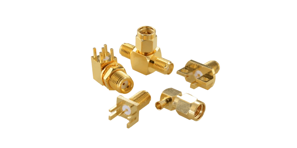
A collection of gold-plated RF coaxial connectors in different mounting configurations. Connector geometry, mounting style, and termination quality can influence impedance matching and VSWR in RF systems.
Start With 1:1, but Do Not Expect to See It Everywhere
A VSWR of 1:1 represents a perfect impedance match. In that ideal case, there is no reflected wave at the measurement plane.
Real RF hardware is less tidy.
A nominal 50-ohm cable assembly may include two connector transitions, solder or crimp terminations, dielectric changes, a short section of exposed center conductor, and perhaps another adapter before the load. Each transition has physical dimensions. At RF frequencies, those dimensions matter.
A tiny difference that is almost irrelevant at 100 MHz may become visible on a VNA trace several gigahertz later.
This is also why a connector marked for DC–6 GHz should not automatically be treated as a complete DC–6 GHz cable assembly specification. The connector may support the frequency range, while poor termination pushes the finished assembly outside the customer’s VSWR limit.
The same issue appears with higher-frequency SMA parts. Using an 18 GHz connector does not repair a badly prepared cable end.
Higher VSWR Means More Reflection, Not Automatically a Failed Product
Buyers sometimes treat VSWR numbers like quality grades.
1.1 must be excellent.
1.5 must be average.
2.0 must be bad.
That shortcut is risky.
The correct limit depends on the product and the job it is doing. An antenna installation may accept a ratio that would be rejected on a precision test cable. A broadband cable assembly can also have a small peak near one band edge without behaving badly everywhere else.
Still, the amount of reflection rises quickly enough that the numbers deserve attention.
The last column is not an acceptance standard. It is only a practical way to read the scale.
A 1.5:1 requirement written into a customer’s drawing still overrides any general rule of thumb.
There is another trap here: reflected power is not the same thing as insertion loss. A cable can have fairly low transmission loss while still containing a local impedance discontinuity that produces poor return loss.
So a “good VSWR” result does not prove that cable attenuation is low.
Never Separate the VSWR Number From Frequency
“VSWR: 1.25”
That line is not enough for a useful inspection report.
A better record would be:
VSWR: 1.25:1 at 2.4 GHz
Better still, save the sweep.
RF mismatch is frequency-dependent. Connector geometry, cable length, termination structure and antenna impedance can all create peaks or ripples at particular frequencies. A cable may measure 1.18:1 at 2.45 GHz and rise above 1.5:1 closer to the edge of the operating band.
This matters when the specification says:
VSWR ≤ 1.5:1 from 2.4 to 2.5 GHz
Testing only at 2.45 GHz does not prove compliance with that requirement.
For production orders, the worst point in the specified band is normally more useful than one favorable center-frequency value.
That is also why two suppliers can report different numbers for what appears to be the same assembly. One may be testing at a single frequency. The other may be reporting the maximum value across the entire sweep.
Do Not Give Every RF Product the Same VSWR Limit
A cable assembly, antenna, attenuator and RF load should not automatically share one VSWR target.
Their job is different.
The test object is different too. A standalone connector can meet its own specification while the completed cable assembly fails because the center conductor was left too long during termination. Add another adapter, and the result may change again.
For sourcing work, vague terms such as “low VSWR” are weak specifications.
That gives the factory something measurable.
It also prevents an argument later about whether the quoted VSWR belonged to the connector, the cable, or the finished assembly.
How Can You Convert VSWR Into Return Loss and Reflected Power?
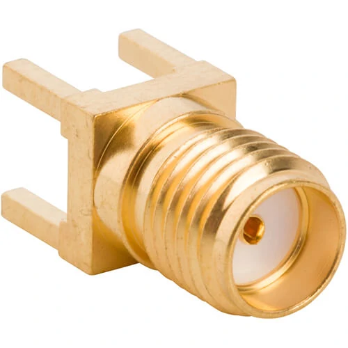
Close-up of a gold-plated SMA female PCB-mount RF connector featuring a threaded interface and four solder pins. Connector interface geometry and PCB integration can affect RF impedance matching and reflection measurements.
VSWR is only one way to describe reflection. RF engineers often look at return loss or S11 instead, especially when reviewing VNA results.
Convert the Same Result Into Return Loss
So a VSWR of 1.5:1 is roughly equivalent to 14 dB return loss.
The direction of the numbers sometimes causes confusion. Lower VSWR is better, while a larger positive return-loss value represents less reflection.
S11 is commonly displayed differently on a VNA. The same reflection magnitude may appear as approximately -14 dB S11 rather than “+14 dB return loss.”
Same reflection. Different reporting convention.
This becomes important when a buyer receives one supplier report showing VSWR and another showing S11. The two documents may not disagree at all; they may simply be using different formats.
One final caution: these calculations describe reflection at the same reference plane. They cannot be used to calculate insertion loss directly. Transmission loss is a separate measurement and should stay a separate acceptance item.
Which Parts of an RF Chain Can Push VSWR Higher?
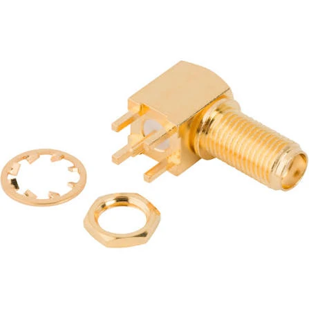
A gold-plated SMA RF connector with a threaded mounting barrel, hex nut, and retaining washer.
High VSWR is rarely enough evidence to blame one connector.
A typical RF path may look simple on a drawing:
RF source → coaxial cable → adapter → connector → antenna
On the bench, every arrow represents another physical transition. If one transition changes the local impedance, part of the signal reflects back toward the source.
That is why troubleshooting should begin with the complete path rather than the most visible component.
Check the Antenna or Load Before Cutting the Cable Apart
A cable often gets blamed first because it is easy to replace.
That may be the wrong move.
If the far end is connected to an antenna, disconnect the antenna and substitute a known 50-ohm matched load. Run the same sweep again without changing the test cable or calibration.
If the trace improves substantially, the cable path may be acceptable and the problem is more likely related to the antenna, its feed point, or the installation around it.
If the VSWR remains high, keep moving backward through the RF chain.
This simple substitution test can save a supplier from opening a perfectly usable cable assembly.
An antenna can also behave differently after installation. A unit that measured well in free space may shift when mounted close to a metal housing, PCB ground structure, battery, bracket, or other conductive material.
The cable is only one suspect.
Look Closely at the Cable Terminations
A coaxial cable depends on geometry.
Center conductor position matters. So does the dielectric, shield termination, ferrule compression, and the amount of conductor exposed inside the connector.
Small assembly errors may not cause an open circuit.
That is exactly why they can be difficult to catch.
A poorly positioned center contact may still pass continuity. Excess solder may still make electrical contact. A slightly damaged dielectric may look acceptable after the connector body is assembled.
The VNA sees what a continuity meter does not.
Typical areas worth checking include:
- center pin depth
- exposed center conductor length
- braid contact
- ferrule position
- solder overflow
- dielectric deformation
- crushed or oval cable
- loose rear-body assembly
A repeated VSWR peak across several production pieces can point toward a process issue rather than random cable damage.
If ten assemblies show a similar peak near the same frequency, inspect how the connector is being terminated before replacing the cable material.
Inspect the Mating Interface Too
Connector damage is not always dramatic.
A slightly recessed female contact can create unstable mating. A bent center pin may still enter the opposite connector but no longer sit concentrically. Worn threads can prevent consistent seating.
Contamination is another quiet problem.
Metal particles, solder residue, dirt, and damaged plating around the contact region can all alter the interface or make measurements less repeatable.
For threaded RF connectors, inconsistent tightening can also change the result. If the first test is finger-tight and the second is properly torqued, the two traces should not automatically be treated as a production variation.
The test method changed.
Count the Adapters
One adapter may have little effect.
Five adapters deserve attention.
Every added connector pair introduces another transition, and the individual reflections can interact across frequency. The result may appear as ripple rather than one obvious failure point.
This is common in development benches where engineers build a temporary path from whatever adapters are available.
The product may then be blamed for a trace that actually includes several test accessories.
A useful rule is simple: remove anything that is not required to test the DUT.
The shortest clean path usually gives the clearest answer.
How Should You Measure VSWR Without Moving the Reference Plane?
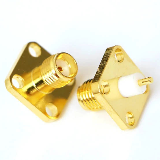
Gold-plated flange-mount RF coaxial connectors featuring square mounting plates and four mounting holes. Secure mechanical mounting and consistent connector mating help establish a repeatable RF test configuration for VSWR measurements.
A good cable can produce a bad result if the measurement setup changes between tests.
Before comparing suppliers, production lots, or reworked assemblies, define what the VNA is actually measuring.
Decide Where the DUT Starts
Suppose the product is an SMA-to-N cable assembly.
If calibration ends directly at the SMA test port, then the cable assembly is inside the measurement reference plane.
If a long test cable and two adapters are added after calibration, their behavior may now appear in the measured trace unless the setup has been compensated correctly.
That difference matters.
Write down the DUT before testing:
Complete SMA-to-N cable assembly, including both terminated connectors.
That sounds basic, but it prevents the test scope from changing halfway through an investigation.
Calibrate Near the Device Under Test
The farther the calibration reference plane is from the DUT, the more fixtures, test cables, and adapters can influence the result.
For routine RF cable testing, calibration should be moved as close as practical to the DUT connection.
Then leave the setup alone.
A common bench mistake is calibrating the VNA, moving the test cable to make more room, changing an adapter, and then continuing as though nothing changed.
Flexible RF test cables are not infinitely repeatable. Bending them differently can alter phase and, in some cases, the measured reflection response.
If the trace suddenly changes, verify the setup before opening a production investigation.
Sweep the Operating Band
Single-frequency checks are fast.
They are also easy to misuse.
A cable specified from 1 to 6 GHz should not be accepted because it measured well at 2.4 GHz.
Mismatch may rise toward the upper band. A connector transition can also create a narrow peak that disappears at the exact frequency chosen for a spot check.
For qualification work, use the full required frequency range and record the worst point.
A useful test record contains more than one number:
| Test Record | Why It Matters | Useful Reading |
| Frequency range | Defines where the requirement applies | Very little reflection |
| Maximum VSWR | Shows the worst measured mismatch | Low mismatch |
| Frequency at maximum | Helps identify repeatable peaks | Clearly measurable |
| Calibration condition | Makes later comparison possible | Significant reflection |
| Reference plane | Defines what was included | Severe mismatch |
| Adapter configuration | Prevents hidden test-path changes | |
| Cable position | Useful when bending affects results |
Saving the trace is even better.
A screenshot or exported data file can show whether the problem is a broad mismatch, a narrow spike, or repeating ripple.
Those patterns often lead to different investigations.
How Can You Separate Cable, Connector, and Antenna Mismatch?
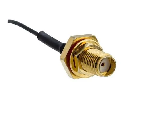
A gold-plated SMA bulkhead RF coaxial connector attached to a black coaxial cable. Testing the complete cable assembly independently and comparing measurements before and after installation can help isolate impedance mismatch and identify changes caused by cable routing or connector mounting.
Do not dismantle the entire RF system at once.
Change one thing.
Then measure again.
Start With a Known Matched Load
Replace the antenna with a verified load while leaving the feed cable in place.
Next, remove unnecessary adapters.
Retest after each change.
This takes longer than replacing everything in one step, but it tells you which change actually affected the measurement.
Test the Cable Assembly by Itself
When possible, remove the cable assembly from the installed system and test it independently.
Compare that trace with the result from the installed condition.
A cable that passes while lying straight on the bench but changes after installation may be experiencing mechanical stress.
Look at the bend near the connector first.
A tight bend directly behind a crimped or soldered connector can pull on the termination. Cable routing may also twist the connector body or disturb an already marginal center-contact position.
Do not assume the cable needs to be visibly kinked before RF performance changes.
Rebuild the Path One Component at a Time
Once the shortest verified RF path passes, add the removed components back.
Cable first.
Then one adapter.
Then the next transition.
Then the antenna.
Retest at each step.
This approach is slower than guessing, but it avoids a common failure-analysis problem: changing three components, seeing the VSWR improve, and still having no idea which component caused the original mismatch.
For supplier disputes, that distinction matters.
A failed complete system test does not automatically prove that the cable assembly itself is defective. The failure needs to follow the component when the surrounding test conditions are controlled.
When Does VSWR Become a Power-Handling Risk?
A VSWR of 2.0:1 means the same ratio whether the transmitter is sending 1 W or 100 W.
The consequences are not the same.
With 1 W forward power, that is roughly 0.11 W reflected.
With 100 W forward power, it is roughly 11.1 W.
That difference is large enough to change the engineering discussion.
Look Beyond the Ratio
High-power RF systems deserve more than a simple pass/fail VSWR check.
Standing waves create voltage and current maxima along the transmission line. Depending on the cable, connector, frequency, and operating conditions, these peaks can contribute to local heating or electrical stress.
A connector that works comfortably in a low-power receiver path may not be suitable for the same VSWR condition in a transmitter.
Cable construction matters too. So do temperature, altitude, duty cycle, connector contact condition, and termination quality.
This is why VSWR should not be used as a substitute for a power rating.
If the application runs significant RF power, specify both.
That gives the supplier something meaningful to evaluate.
How Should You Set VSWR Limits Across Frequency?
“Low VSWR” is not a specification.
Neither is “good matching.”
If a cable assembly must work from 700 MHz to 3 GHz, write the requirement across that entire band.
A practical format is:
VSWR ≤ 1.5:1 from 700 MHz to 3 GHz
The worst measured point is normally the number that matters.
An average VSWR can hide a narrow peak. A center-frequency result can hide problems near the band edge.
Test the Finished Assembly
Connector datasheets are useful, but a connector specification is not automatically the specification of the completed cable.
A finished RF assembly contains more than the front interface:
Connector → termination → cable → termination → connector
Each transition contributes to the final response.
For prototype approval, a full VNA sweep is usually worth saving. Production inspection can then be simplified according to the risk of the project.
A low-cost cable operating well below its upper frequency limit may only need sampling.
A sensitive cable used near the top of its operating band may justify tighter inspection or even 100% RF testing.
That decision belongs in the purchase requirement before production starts.
How Can You Calculate VSWR Before Accepting the RF Path?
A few conversions make a VSWR report much easier to read.
The four values most commonly linked together are:
- VSWR
- reflection coefficient
- return loss
- reflected power
A quick conversion table is often enough for production and sourcing work.
| VSWR | Return Loss | Reflection Coefficient | Reflected Power |
| 1.05:1 | ≈32.3 dB | 0.024 | ≈0.06% |
| 1.10:1 | ≈26.4 dB | 0.048 | ≈0.23% |
| 1.20:1 | ≈20.8 dB | 0.091 | ≈0.83% |
| 1.50:1 | ≈14.0 dB | 0.2 | 4.00% |
| 2.00:1 | ≈9.54 dB | 0.333 | ≈11.11% |
| 3.00:1 | ≈6.02 dB | 0.5 | 25.00% |
This table is useful when one supplier reports VSWR and another reports return loss.
They can still be describing the same reflection level.
How Should Buyers Write VSWR Requirements Into an RF Specification?
A good RF purchase specification should remove room for interpretation.
That detail can matter in compact enclosures where the production cable is never used straight.
Keep insertion loss separate.
A supplier may meet the VSWR requirement and still exceed the customer’s loss budget. Reflection and transmission are related to the same RF path, but they are not interchangeable acceptance items.
FAQ
Can a cable have low insertion loss but poor VSWR?
Yes. A local impedance discontinuity may create reflection without causing large transmission loss. Both measurements should be checked when the application is sensitive.
Should I test VSWR with the antenna connected?
Use the antenna when evaluating the complete installed system. Use a known 50-ohm load when you want to isolate the cable and feed path.
Why can bending a coaxial cable change the result?
A tight bend can disturb cable geometry or place mechanical stress on the connector termination. The effect depends on cable construction and bend severity.
Is a basic VSWR meter enough for production testing?
Sometimes. For broadband or tighter specifications, a VNA sweep provides much more useful information, including the worst point across frequency.
What should a supplier report for broadband assemblies?
At minimum: test frequency range, maximum measured VSWR, frequency of the worst point, test method, and the defined DUT. Saving the trace is better when repeatability or failure analysis matters.