
A customer approved the first SMA cable sample after a simple bench test. The connector fitted correctly, the cable length matched the drawing, and the signal passed.
Three weeks later, the production version showed unstable measurements.
The reason was not the SMA interface.
The cable routing changed inside the equipment housing. The bend radius became smaller than the prototype. The production team also added an adapter during installation. The assembly still looked identical from the outside, but the RF path was no longer the same.
This type of problem is common in RF sourcing. A cable assembly is often treated as a simple connection accessory, while in reality it is a complete transmission path that includes the connector, coaxial cable, termination process, and inspection method.
For engineers ordering an SMA cable assembly, the important information is not only the connector name. The supplier needs to know where the cable will be used, what frequency range is required, how much loss is acceptable, and how the assembly will be installed.
A correct specification at the beginning usually costs less than correcting unstable RF performance after mass production.
Why Do RF Systems Use SMA Cable Assemblies Instead of Separate Components?
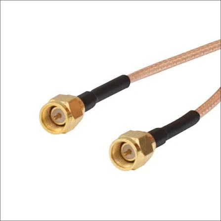
This image shows an SMA male to male cable assembly with coaxial RF cable. The assembly combines SMA connectors and flexible coaxial cable to provide a stable RF connection solution for antenna systems, wireless devices, communication equipment, and RF testing applications.
In a prototype stage, some engineers prefer buying connectors and cables separately because it allows more flexibility. However, once a design moves toward repeatable production, separately sourced components can create unnecessary variables.
The final RF performance depends on several details:
- SMA connector interface accuracy
- coaxial cable structure
- center conductor alignment
- shielding contact
- termination method
- cable length tolerance
- final RF inspection
A cable assembly supplier is not only providing a cable with two connectors attached. The supplier is controlling the process that turns individual parts into a repeatable RF component.
For applications such as RF test fixtures, antenna modules, wireless devices, and communication equipment, repeatability is usually more important than simply having a connector that fits.
What Problems Can Appear When SMA Cable Assemblies Are Poorly Specified?
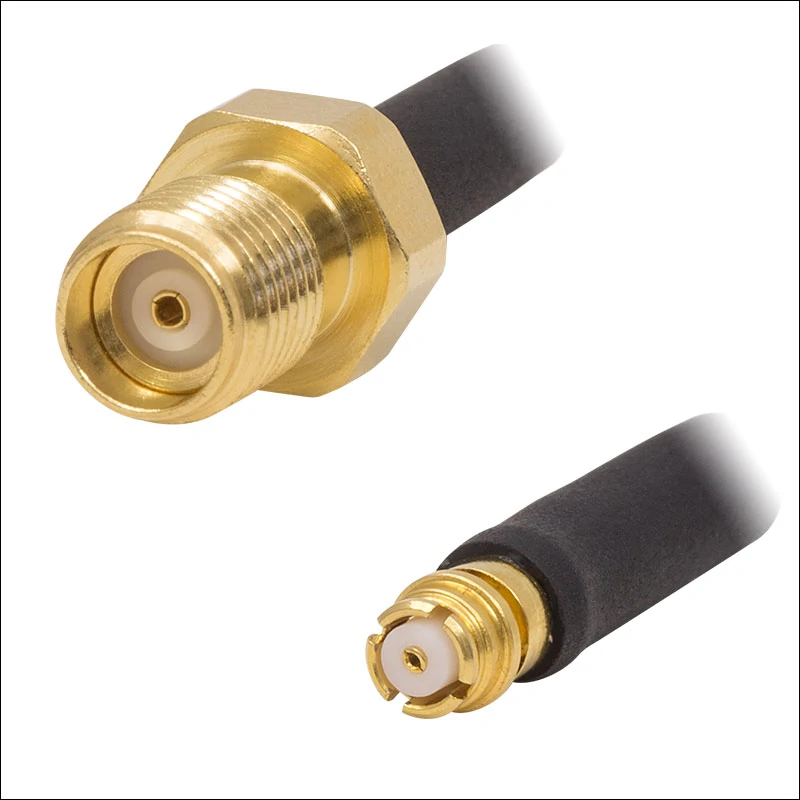
This image displays a right angle SMA cable assembly with a bulkhead mounting connector. The design allows easier installation in limited spaces and is commonly used in RF modules, antenna systems, wireless communication equipment, and test fixtures requiring reliable coaxial signal transmission.
Many RF assembly problems begin before production.
does not define enough information.
For example, an SMA assembly using a thin flexible cable may be suitable for an embedded wireless module. The same cable may not be a good choice for a laboratory test connection where lower loss and mechanical stability are more important.
The connector is only one part of the RF path.
How Does a Complete SMA Cable Assembly Improve Production Consistency?
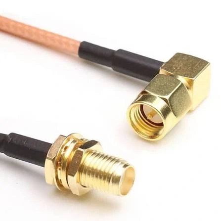
This image shows an SMA female to male RF cable assembly designed for connecting different SMA interfaces. The flexible coaxial cable structure provides installation flexibility and is suitable for RF testing equipment, antenna connections, wireless modules, and communication systems.
Production engineers often encounter a difference between prototype success and mass-production stability.
A prototype may be assembled carefully by an experienced technician. A production line may require hundreds or thousands of identical assemblies. Small differences in stripping length, solder temperature, crimp force, or connector positioning can affect the result.
Which Applications Usually Require Custom SMA Cable Assemblies?
Custom assemblies are often selected when standard jumper cables cannot match the equipment requirements.
A custom assembly does not always mean a completely new design.
Many projects only require selecting the correct combination from existing options:
- SMA male or female interface
- straight or right-angle connector
- RG178, RG316, RG405 or other coaxial cable
- specific cable length
- required inspection method
The goal is to create an assembly that matches the actual RF environment.
SMA Cable Assembly Specification Checklist
This checklist avoids a common communication problem between engineering and purchasing teams: the purchasing department orders a cable based on appearance, while the engineering requirement is actually related to RF performance.
How Should Engineers Confirm the SMA Interface Before Ordering?
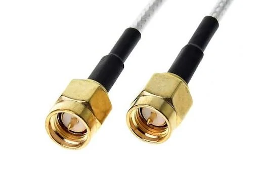
This image presents a flexible SMA RF cable assembly with coaxial cable. The cable assembly can be customized with different SMA connector configurations, cable lengths, and coaxial cable types to meet requirements for RF devices, antennas, test systems, and communication applications.
The first confirmation should be mechanical compatibility.
In some cases, unnecessary adapters are added because the original interface was not confirmed clearly.
Each additional adapter creates another connection point in the RF path.
For low-frequency applications, this may have little impact. Near the upper operating range, additional transitions can contribute to mismatch and signal loss.
Why Does Cable Selection Matter as Much as the SMA Connector?
A frequent sourcing misunderstanding is that the connector determines the entire frequency capability of the assembly.
In practice, the cable often becomes the limiting factor.
When selecting an SMA cable assembly, engineers should check:
- cable diameter
- flexibility requirement
- attenuation
- shielding structure
- installation environment
A compact device may need a small and flexible cable. A test setup may require a more stable cable structure. Neither choice is universally better; the correct selection depends on the RF application.
The next step is comparing common cable options such as RG178, RG316, and RG405, because the cable structure directly affects SMA assembly design, loss, and installation limitations.
Match the Coaxial Cable Before Finalizing an SMA Cable Assembly
The connector is usually the first item shown on a drawing.
A purchasing document may start with:
“SMA male to SMA female cable, 300 mm.”
From the connector description, the requirement seems clear. However, the missing information is often inside the cable.
The same SMA interface can be assembled with different coaxial cables. The final result changes with cable diameter, dielectric material, shielding structure, and length.
During prototype testing, a short cable may hide these differences. After installation, the cable may be routed around a metal frame, placed near other components, or extended to a different length. The original test condition no longer exists.
This is why cable selection should happen together with connector selection.
They are not interchangeable replacements. Each cable has its own suitable working environment.
Where Does RG178 Fit in Small RF Equipment?
In compact electronic products, available space often decides the cable choice.
A thick coax cable may have acceptable RF characteristics, but it may not physically fit inside the product structure. Designers working on small wireless devices, sensors, or embedded modules often need a cable that can pass through narrow areas.
RG178 is used in these situations because of its small outside diameter.
Typical examples include:
- internal antenna connections
- compact communication modules
- miniature RF assemblies
- space-limited test fixtures
The smaller structure also means engineers need to check the operating conditions more carefully.
A short RG178 connection inside a compact device can be a practical solution. A longer cable used for RF measurement may require a different approach.
Why Do Many RF Projects Use RG316 Cable Assemblies?
It provides a useful balance between size and flexibility. Technicians can route it around equipment without the handling difficulty of semi-rigid cable.
Common applications include:
- antenna extension cables
- wireless module connections
- internal RF wiring
- laboratory jumper cables
For example, a device manufacturer may need several hundred SMA cables with identical length and connector orientation. RG316 is often considered because it is easy to process and widely available.
However, the production quantity does not remove the need for checking electrical requirements.
A 50 mm cable and a 1000 mm cable using the same RG316 material do not have the same RF behavior.
Before confirming production, engineers should review:
- frequency range
- acceptable attenuation
- connector quantity
- installation environment
A cable suitable for a short internal connection may not provide enough margin for a longer external connection.
When Is RG405 a Better Choice for Fixed RF Connections?
Some RF systems are installed once and rarely moved.
RG405 is a semi-rigid coaxial cable. Unlike flexible cables, it can maintain a formed routing shape after installation.
This characteristic helps when engineers need:
- fixed cable position
- repeatable assembly dimensions
- reduced movement around the connector area
The limitation is also practical.
A semi-rigid cable is not intended for applications where operators frequently bend or reposition the cable.
During design review, the installation condition should be considered together with the electrical specification.
A cable that performs well in a fixed test fixture may create unnecessary installation difficulty in a handheld device.
SMA Cable Assembly Cable Selection Matrix
The following checklist can help engineers narrow down cable options before requesting samples.
This table is not a substitute for RF testing. It is a first screening step before sample evaluation.
The final decision should still consider frequency, cable length, connector design, and required test results.
Why Can the Wrong SMA Connector Still Cause Assembly Problems?
A connector can look correct from the outside and still fail during production.
The reason is the rear section of the connector.
The cable side of an SMA connector must match:
- cable outer diameter
- center conductor size
- dielectric structure
- shielding method
- termination process
For example, a connector designed for RG316 cannot automatically be used for a larger cable by changing only the assembly method.
The front SMA interface may remain unchanged, but the internal connection between cable and connector determines mechanical strength and RF consistency.
What Information Should Be Included in an SMA Cable Assembly Request?
Many delays between engineering teams and suppliers happen because the initial request contains only the connector name.
This information helps suppliers avoid incorrect substitutions.
How Does Cable Length Influence SMA Assembly Loss?
Cable length is directly related to signal loss.
A longer assembly contains more transmission distance, which means the coaxial cable contributes more attenuation.
This is especially important for test cables.
A short prototype cable may produce acceptable measurement results. After changing to a production length, the additional loss may affect the available RF margin.
What Should Be Confirmed Before Moving From Sample Approval to Mass Production?
A sample represents one assembly condition.
Mass production represents thousands of repeated assemblies.
Before release, confirm that production will keep the same:
- cable source or specification
- connector model
- termination method
- assembly dimensions
- inspection requirements
A common production issue appears when a substitute cable is introduced because it looks similar or is easier to purchase.
The cable may still connect correctly, but the RF characteristics can change.
For SMA cable assemblies, the approved sample should become the production reference, including the cable details behind the connector.
Custom Assembly Problems Usually Appear Before Production Starts
Many SMA cable assembly projects do not fail because of manufacturing capability.
They fail because the first specification was incomplete.
A customer may send a product photo and ask for the “same cable.” From the appearance, the connector looks easy to identify. The difficulty comes from the details that cannot be seen in the picture.
The supplier still needs to confirm:
- the actual SMA interface
- the coaxial cable model
- the required length
- the installation position
- the expected RF performance
This situation happens frequently with replacement cables.
The old cable may have been purchased several years ago. The label is missing. The equipment is still running, but the original drawing is unavailable.
At this stage, copying the appearance is usually not enough.
The supplier needs to rebuild the specification before producing a new SMA cable assembly.
What Engineers Usually Confirm During the First Communication
A useful RF discussion normally starts with the application.
A test engineer may care about insertion loss and repeatability.
A product engineer may care more about cable routing and connector direction.
A purchasing team may first focus on quantity and delivery time.
All of these requirements affect the final assembly.
The purpose of this information is not to make the order complicated.
It prevents a common situation where the sample looks correct but cannot be installed or tested properly.
The Assembly Process Behind the Connector
Most customers see the finished SMA connector.
The production team sees the steps behind it.
The cable needs to be prepared according to the connector structure. The stripping dimensions, conductor position, and shielding contact all influence the final connection.
During assembly, operators need to control several details.
For example:
A center conductor that is slightly out of position may still pass a simple electrical check.
A weak shield connection may not create an immediate failure.
A cable that was bent too close to the connector may work during inspection but fail after installation.
These issues explain why RF cable production usually requires both process control and testing.
Why Sample Approval Does Not Always Mean Production Approval
The first sample is normally produced with extra attention.
An engineer may check the cable carefully.
A technician may spend more time adjusting the assembly.
Mass production is different.
The supplier needs to repeat the same process hundreds or thousands of times.
Before moving into production, it is worth confirming:
- the cable specification has not changed;
- the connector model is the same;
- the assembly length matches the approved sample;
- the inspection method is unchanged.
One common problem is replacing a cable with a similar alternative.
The outside diameter may be almost identical.
The connector may still fit.
The final RF result, however, can change because the internal construction is different.
RF Testing Should Match the Application
Not every SMA cable assembly needs the same test standard.
A short cable inside a finished product and a laboratory measurement cable have different requirements.
For a normal production check, basic electrical inspection may be enough.
For RF measurement applications, engineers often check additional parameters:
| Measurement | Application Concern | Main Reason |
| Continuity | Connection status | Small diameter routing |
| VSWR | Matching condition | Easier installation and common availability |
| Insertion Loss | Signal reduction | Stable mechanical position |
| Return Loss | Reflected energy | Better handling |
| Installation | Internal / External | Repeatable routing |
| Test Requirement | According to application | |
| Working Frequency | Required band | |
| Test Requirement | VSWR / Insertion Loss |
A continuity result only tells whether the circuit is connected.
It does not tell whether the RF signal is travelling through the cable as expected.
This difference is important when the assembly operates near the upper frequency limit.
Keep a Production Reference for Repeat Orders
Repeat orders are common for SMA cable assemblies.
A customer may reorder the same cable after six months or one year.
Without a clear reference, small changes can appear:
- different cable supplier;
- different connector batch;
- different assembly method;
- different inspection record.
The easiest way to avoid confusion is keeping the approved sample information.
A practical record may include:
| Record | Content |
| Product Name | SMA Cable Assembly |
| Connector Combination | SMA Male to SMA Female |
| Cable Model | RG316 |
| Length | 500 mm |
| Approved Test | VSWR / Loss |
This record becomes the reference for future production.
FAQ
Can a supplier make an SMA cable assembly from a product photo?
A photo can help identify the general structure, but it normally cannot confirm cable type, impedance, frequency requirement, or internal construction. Additional information is needed before production.
I need the same SMA cable assembly as before. Is a product photo enough?
A photo can show the connector style, but it usually cannot confirm the cable used inside. For a repeat order, it is better to check the previous drawing, cable model, length, or sample record. This avoids making a cable that looks the same but performs differently after installation.
Do I need RG316, RG178, or RG405 for an SMA cable assembly?
RG178 is often considered when the available space is limited. RG316 is commonly selected for flexible connections. RG405 is usually used where the cable needs to keep a stable shape after installation. The cable type should match the equipment layout and RF requirement, not only the connector interface.
I see RG178, RG316, and RG405 SMA cables. How do I decide which one to use?
The choice usually comes from the equipment design. A compact device may need a smaller cable for routing space. A flexible jumper may require easier handling. A fixed installation may need a cable that keeps its shape. The connector type alone cannot decide the suitable cable.
