
A connector can be electrically acceptable and still be the wrong interface for the product.
This happens often during RF hardware development. An engineer starts with an SMA port because the prototype PCB is compact. Later, the same unit is expected to sit on a test bench where operators reconnect cables dozens of times each day. Another project begins with BNC because the existing laboratory equipment already uses it, then discovers that the connector body consumes too much space on the final enclosure.
That is the useful way to approach SMA vs BNC connector selection. The question is not simply which connector is smaller or which one supports a higher frequency. The better question is: what does the port have to do throughout the life of the product?
Interface location, operator access, mating frequency, cable routing, impedance, mechanical retention, PCB layout, and production servicing can all change the answer.
For a broader comparison that also includes N-type interfaces, see TEJTE’s SMA vs BNC vs N-Type comparison. Here, the focus is narrower: deciding between SMA and BNC while the RF architecture is still being designed.
Which Port Architecture Favors SMA or BNC?
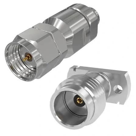
Examples of compact threaded RF connector structures for cable and PCB mounting, highlighting the importance of connector size, mounting geometry, and frequency rating.
Start with the equipment, not the connector catalog.
Before comparing an SMA connector with a BNC connector, identify exactly where the interface sits in the system. A connector used between a PCB and an internal coax cable has a different job from a connector mounted on the front panel of a spectrum analyzer.
Start With the Fixed Equipment Role
A useful first step is to classify the port:
- external user-access port
- laboratory test port
- PCB or RF module interface
- enclosure feedthrough
- production test fixture
SMA often fits naturally into compact equipment because the interface occupies relatively little panel and PCB space. That can matter when several RF ports must sit beside USB, Ethernet, power, antenna, or control interfaces.
But density is not always the main constraint.
A laboratory test port may be physically large enough for either connector. In that case, technicians may care more about how quickly cables can be changed and how the interface behaves after repeated handling. That moves the decision toward workflow rather than size.
An external port also changes the mechanical problem. Users may pull the cable sideways, reconnect it without controlled torque, or operate the equipment while wearing gloves. A connector that looked ideal on the CAD drawing may become inconvenient once installed between other panel controls.
This is why an RF interface should be selected as part of the equipment architecture rather than as an isolated BOM item.
Separate Product-Design Decisions From Adapter Problems
There is also an important distinction between selecting a connector for a new product and connecting two pieces of equipment that already exist.
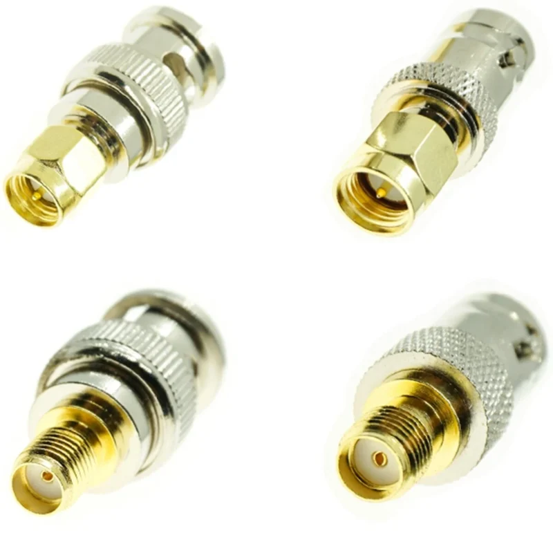
If one instrument already has SMA and another has BNC, the engineering task is interface conversion. An SMA-to-BNC adapter or cable assembly may solve it without redesigning either device.
A new product is different.
If the design team already knows that every finished unit will require an SMA-to-BNC adapter, that adapter should not automatically become a permanent part of the architecture. It adds another RF transition, another mechanical joint, another sourcing item, and another place for operators to loosen or damage the connection.
During the design phase, ask whether the equipment should simply use the required connector family directly.
How Does Coupling Style Change the Service Workflow?
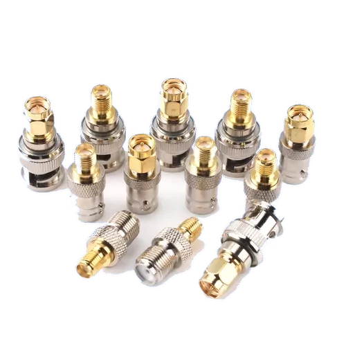
A selection of SMA and BNC connector adapters with different male and female interface combinations for RF equipment connection and signal testing.
The mechanical coupling is one of the clearest differences in a BNC vs SMA comparison.
SMA uses threaded coupling. BNC uses a bayonet-style locking mechanism. Both can be suitable RF interfaces, but they create very different operator behavior.
Evaluate SMA Threaded Coupling for Controlled Retention
With SMA, mating is deliberate.
The user aligns the interfaces, engages the threads, and tightens the coupling. In controlled RF measurement setups, the connection can also be tightened according to the procedure required by the equipment or connector manufacturer.
That threaded structure can be useful when accidental release is undesirable. It also works well where the connection will remain installed for long periods.
The trade-off appears when access becomes difficult.
Place several SMA ports too close together and fingers may not have enough room to rotate the coupling nut. Add a large cable boot or a nearby enclosure wall and tool access may become restricted as well.
So “SMA is smaller” does not automatically mean “SMA requires less usable space.” The design must include the space needed to mate it.
Evaluate BNC Bayonet Coupling for Fast Access
BNC takes a different approach.
Its bayonet coupling allows the operator to insert the connector and lock it with a short twisting action. That is one reason BNC remains common on laboratory equipment, oscilloscopes, signal sources, test fixtures, and other panels where cables are changed regularly.
The advantage is not simply “faster.”
It reduces the amount of repeated threading work required during routine connection changes. On a production test bench where an operator reconnects DUTs throughout a shift, that difference can affect usability and test throughput.
The cost is physical envelope. A typical BNC interface needs more front-panel area than SMA, and the designer still has to account for the cable body and the operator’s hand.
Compare Operator Time With Connection Security
Avoid turning this into an absolute rule.
SMA is not automatically the better connector whenever retention matters, and BNC is not automatically the better connector whenever users need quick access. Connector quality, installation, cable load, vibration, surrounding geometry, and actual operator behavior all matter.
A useful design review asks two separate questions:
- How quickly must the connection be changed?
- How much mechanical control must the interface maintain after it is connected?
If the equipment spends years with the same cable attached, saving a few seconds during mating has little value. If a technician changes cables hundreds of times during development or production testing, those seconds become part of the workflow.
That is where SMA vs BNC stops being a catalog comparison and becomes a product-design decision.
How Much Panel and PCB Space Does Each Interface Consume?
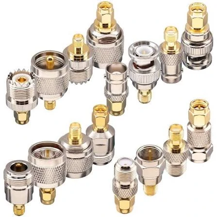
Multiple RF coaxial adapter configurations combining SMA, BNC, and N-type interfaces for equipment connection, testing, and system integration.
Mechanical space is more complicated than connector diameter.
A connector that looks compact in a catalog drawing may need extra room for the coupling mechanism, mounting hardware, cable bend, assembly tooling, and the operator’s fingers. That difference matters when comparing an SMA PCB connector with a BNC panel interface.
Compare Connector Envelope, Not Only Mating Diameter
The usable envelope should include more than the front interface.
Check:
- connector body diameter
- coupling clearance
- mounting nut and washer
- PCB footprint
- cable exit direction
- minimum practical bend space
- distance to neighboring connectors
- access for installation and servicing
This becomes especially important on compact enclosures.
A designer may place four SMA ports closely together because the mating interface is small, then discover that the selected cables have large strain-relief boots that interfere with adjacent ports. The connector fits. The finished assembly does not.
The same issue appears behind the panel. A right-angle cable route may need more depth than expected, while a straight connector may force the coax into a tighter bend than the cable should tolerate.
Evaluate SMA for Dense PCB and Compact Enclosures
SMA is frequently practical when PCB area and enclosure volume are limited.
PCB-mounted SMA interfaces can place the RF connection directly at the board edge or through the board, depending on the connector style. This can reduce the need for an internal cable assembly and make the RF path mechanically compact.
But the launch geometry matters.
The transition from PCB transmission line to connector pin is part of the RF structure. Ground placement, pad geometry, board thickness, dielectric properties, and soldering quality can influence the measured result.
That means replacing one SMA PCB connector with another purely because the footprint appears similar can create a production problem. Mechanical compatibility does not automatically guarantee equivalent RF behavior.
A sourcing team should therefore freeze the connector part number together with the approved PCB footprint and launch geometry rather than specifying only “SMA female PCB connector.”
Evaluate BNC Where Front-Panel Access Matters More Than Density
BNC often makes more sense when the panel is designed around human access rather than maximum connector density.
Test equipment is a typical example. The larger body is less attractive for a small wireless module, but it can be convenient on equipment where operators repeatedly connect probes, cables, fixtures, and external instruments.
The engineering trade-off is straightforward: panel area is consumed in exchange for faster access and easier handling.
That trade may be acceptable on a rack unit or benchtop instrument and unacceptable on a handheld device.
Check Cable Bend Space Behind the Panel
Do not assume a smaller front connector creates a smaller complete installation.
The cable may dominate the rear envelope.
A compact SMA interface connected to a relatively stiff coax can require more rear clearance than a larger BNC using a more flexible cable. Cable OD, dielectric construction, shielding, bend radius, and strain relief all influence the final geometry.
For that reason, enclosure CAD should include the actual cable assembly rather than a connector-only model.
When Does 50Ω or 75Ω Compatibility Become the Deciding Factor?
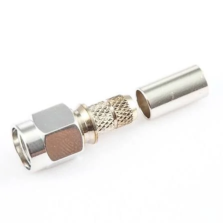
An SMA crimp cable connector with a separate ferrule, illustrating the rear termination structure used to secure compatible coaxial cable.
Impedance can eliminate one option before mechanical preferences are even considered.
Standard SMA RF interfaces are generally used in 50Ω RF systems, while BNC is commonly encountered in both 50Ω and 75Ω versions. The important purchasing lesson is simple: do not identify impedance from the connector family name alone.
Keep Standard SMA Inside the Intended 50Ω RF Path
For RF equipment designed around a 50Ω signal path, SMA is usually straightforward from an impedance-planning perspective.
The more common problem is not the word “SMA” on the BOM. It is everything behind it.
A connector may be 50Ω, but the complete assembly can still show poor return loss if the PCB launch, cable termination, center contact, solder joint, or adapter transition is wrong.
That is why an SMA RF connector should be evaluated as part of the complete RF path.
Verify Whether the BNC Side Is 50Ω or 75Ω
BNC needs an additional check because both impedance families exist.
This becomes relevant when RF test equipment overlaps with video, broadcast, instrumentation, or legacy systems. Two connectors may appear mechanically similar, yet the system requirements behind them may differ.
A practical RF comparison therefore looks like this:
| Design Check | SMA | BNC | Procurement Risk |
| Typical RF system impedance | 50Ω | 50Ω or 75Ω versions | Ordering by appearance |
| Mechanical interface | Threaded | Bayonet | Assuming mating equals compatibility |
| PCB use | Common in compact RF designs | Possible, often panel-oriented | Ignoring launch geometry |
| Panel density | Usually higher | Usually lower | Checking front diameter only |
| Operator access | More deliberate mating | Faster connect/disconnect | Ignoring actual service workflow |
The table is not a substitute for the supplier drawing or RF specification. Its purpose is to show where sourcing mistakes usually begin.
Treat Mechanical Mating and Electrical Matching as Separate Checks
A connector that physically attaches is not automatically electrically correct.
Engineering should verify separately:
- impedance
- operating band
- return loss or VSWR requirement
- insertion loss where relevant
- connector condition
- cable or PCB transition
This distinction becomes even more important when adapters are involved.
A standard SMA-to-BNC adapter changes the mechanical interface. It should not be treated as an automatic 50Ω-to-75Ω impedance transformer.
How Should Frequency and Measurement Repeatability Be Compared?
Frequency ratings are often reduced to a single catalog number. That is rarely enough for an engineering decision.
Use the Exact Part Rating Instead of a Family Maximum
Connector families contain different body designs, PCB launches, cable terminations, materials, and manufacturing tolerances. The exact part number is what matters.
A nominally high-frequency connector can still perform poorly when installed on the wrong PCB launch or terminated badly to the cable.
The reverse is also true: an assembly can meet its required operating band without using the highest-rated connector available.
Compare Repeatability at the Real Mating Condition
For measurement ports, mating repeatability can matter almost as much as nominal bandwidth.
Repeated measurements may shift because of:
- connector wear
- contamination
- inconsistent tightening
- cable movement
- damaged center contacts
- changing adapter stacks
- unstable calibration reference planes
The connector should therefore be evaluated under the way it will actually be used.
A production fixture that is connected once per shift has a different reliability problem from a development bench where the same port is touched dozens of times per hour.
Include PCB Launch and Cable Termination in the Measurement
The connector does not operate alone.
For a PCB-mounted SMA, the launch may become the limiting transition. For a BNC cable assembly, the cable termination, braid contact, or center conductor preparation may introduce more variation than the front interface.
This is why continuity testing is not enough. A cable can pass continuity and still show unacceptable RF behavior near the top of the operating band.
Where RF performance matters, test the finished path under the intended installation condition.
That gives engineering a much more useful BNC vs SMA connector comparison than relying on family-level frequency numbers.
Which Coax Cable and Termination Strategy Fits Each Connector?
A connector drawing can look perfect until the cable is added.
This is especially common with SMA assemblies. The front interface may fit the enclosure, yet the rear body was designed for a different cable diameter. Then production has to improvise: change the ferrule, reduce the jacket, add heat shrink, or force the cable into a bend that was never part of the original design.
None of those is a good place to start mass production.
For an SMA cable connector, the cable should be confirmed together with the connector rather than after the connector has already been approved. RG316 may make sense inside a small enclosure because it routes easily. RG58 is physically larger and may need more room behind the panel, but that does not make it a worse choice when the assembly actually needs that cable construction.
BNC assemblies have the same problem. A BNC cable connector should not be selected simply because the equipment has a BNC port. Rear termination dimensions still need to match the cable.
A cable substitution deserves attention too. If engineering qualified one assembly with RG316, purchasing should not replace it with another nominally 50Ω cable only because the outside diameter looks close.
The connector may still assemble. The RF result may not stay the same.
When Is an SMA-to-BNC Transition Acceptable in Production?
Adapters are not automatically a problem. They become a problem when nobody remembers why they are there.
Suppose a test rack already uses BNC outputs and a newly developed module has an SMA input. Redesigning either side just to eliminate one adapter probably makes little commercial sense. In that case, a properly specified SMA to BNC adapter is doing exactly what it should do.
The decision changes when the adapter becomes part of every production unit.
Then a second adapter appears because the cable stock has another interface. A few revisions later, nobody wants to change the approved cable, so the finished RF path contains several mechanical transitions.
The unit may still pass.
But now there are more contact interfaces to inspect, more joints that can loosen, and more places where a return-loss problem can hide.
Port alignment matters as well. If two fixed ports do not line up, a short flexible SMA-to-BNC cable is often mechanically kinder than a rigid adapter. The cable can absorb a few millimeters of offset. A solid adapter cannot; the load goes directly into the equipment connector.
That distinction is covered in more detail in TEJTE’s SMA-to-BNC cable selection guide.
How Should Engineering Freeze the Chosen Interface Before Production?
Once the interface is approved, remove vague wording from the BOM.
“BNC connector” is not enough.
“SMA female” is not enough either.
The drawing and BOM should identify the exact connector PN, impedance, gender, mounting arrangement, cable or PCB launch, and the approved revision. If the connector is part of a cable assembly, cable type and finished length belong in the same control package.
RF acceptance limits should also be written down before the first large order.
A supplier cannot consistently inspect against “good RF performance.”
They can inspect against something measurable: operating band, VSWR or return-loss limit, insertion-loss requirement where needed, continuity, dimensions, and workmanship criteria.
A change should trigger revalidation when it affects the RF path. Typical examples include a new connector supplier, another cable PN, a PCB footprint revision, different panel thickness, or an adapter being added after qualification.
This is where a lot of avoidable sourcing trouble starts. The first sample works, purchasing approves it, then one small component changes six months later and everyone assumes the assembly is still equivalent.
Sometimes it is.
Sometimes the VNA says otherwise.
FAQ
Can SMA be used inside the product while BNC is used on the external panel?
Yes. There is no requirement for every RF boundary in the product to use the same connector family. The complete path still needs to meet impedance, frequency, loss, and mechanical requirements.
Can a normal adapter match 50Ω SMA to 75Ω BNC?
Not by itself. A standard adapter changes the physical interface. It should not be assumed to perform impedance transformation.
Is SMA always better for compact equipment?
Usually it helps with density, but not automatically. Cable bend space, finger access, wrench clearance, and the rear termination can consume more room than the connector drawing suggests.
Is BNC better for a production test station?
It can be. If operators change cables frequently, the bayonet coupling may save handling time. The exact fixture, mating-cycle requirement, and RF performance still need to be checked.
Can we change the cable after the connector has already been approved?
Only after checking compatibility again. Cable diameter, termination geometry, attenuation, flexibility, and RF behavior may all change.