
A connector can look correct on the assembly drawing and still create problems after the equipment enters testing.
A common RF sourcing issue appears when a device requires an external antenna port or test interface. The engineer selects an SMA connector by appearance, confirms that the thread matches, and the first sample connects normally. However, after installation into the enclosure, the connector position shifts slightly, the cable routing becomes tighter, or the system is tested near the upper frequency limit. The result may be unexpected VSWR variation, unstable measurements, or repeated field complaints.
This is where an SMA female bulkhead connector is different from a standard cable connector. It is not only an RF interface. It is also a mechanical mounting component that becomes part of the equipment structure.
For engineers and buyers, the important question is not simply “Does the SMA connector fit?” The real question is whether the connector, mounting method, cable assembly, and RF requirements are matched before production starts.
Why Are SMA Female Bulkhead Connectors Used in RF Systems?
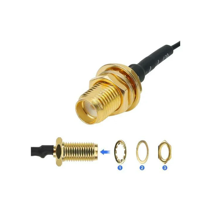
This image displays an SMA female bulkhead connector with mounting nut and washer, commonly used to create a fixed external RF connection point on equipment panels, enclosures, and antenna interfaces.
An SMA female bulkhead connector is commonly selected when an RF system needs a fixed external connection point through an enclosure wall or equipment panel.
Unlike a cable-end SMA connector, which moves together with the cable, a bulkhead version is mechanically fixed. The connector body passes through the panel, while the external SMA female interface remains available for connection with antennas, test cables, adapters, or other RF devices.
The structure usually includes:
- SMA female interface with threaded coupling;
- center socket contact;
- dielectric insulator;
- metal body with panel mounting section;
- rear termination area for cable, PCB, or internal RF connection.
In practical equipment design, the connector often becomes the transition point between the internal RF circuit and the outside environment.
This fixed interface is useful because technicians can access the RF path without opening the enclosure. It also allows repeated connection and disconnection during development, calibration, and maintenance.
Understand the role of female bulkhead interfaces in RF equipment
For these applications, the connector must satisfy two different requirements at the same time:
Mechanical requirement
The connector needs to remain stable after installation.
Important factors include:
- mounting hole size;
- panel thickness;
- fixing nut or mounting structure;
- connector length behind the panel;
- cable bending space.
Electrical requirement
The connector needs to maintain the expected RF characteristics.
Important factors include:
- 50Ω impedance;
- operating frequency;
- VSWR;
- insertion loss;
- return loss.
A connector may pass a simple continuity test while still creating RF issues at higher frequencies. This happens because DC connection only confirms that the conductive path exists. It does not verify the behavior of the RF transition.
Identify why fixed female RF ports are required in equipment design
For many RF products, a fixed connector location is easier to manage than a loose cable connection.
A bulkhead design provides several practical advantages:
| Application Requirement | Why Bulkhead Mounting Helps |
| RF test equipment | Provides repeatable connection points for measurement |
| Communication device | Creates accessible external RF ports |
| Antenna system | Allows antenna replacement without opening equipment |
| Enclosure design | Supports through-panel installation |
| Laboratory fixture | Simplifies repeated testing |
The mechanical fixing point is especially useful during production. If a connector moves slightly every time a cable is connected, measurement results can vary. A properly installed bulkhead connector reduces this mechanical uncertainty.
The internal cable, termination method, and operating frequency still need to be considered.
For example, a short internal RG316 cable connected to a low-frequency module may have different requirements from a test fixture operating near microwave frequencies. The same SMA interface does not mean the same RF result.
How Does an SMA Female Bulkhead Connector Connect Internal RF Modules With External Interfaces?
In many designs, the SMA female bulkhead connector acts as a bridge between a protected internal circuit and external RF components.
The internal connection method depends on the equipment structure. Common options include:
| Connection Method | Typical Application | Design Consideration |
| Coaxial cable termination | RF modules and antenna systems | Match cable type and connector rear structure |
| PCB mounting | Compact RF devices | Control grounding and RF layout |
| Panel feed-through | Test panels and enclosures | Confirm panel thickness and mounting size |
| Custom cable assembly | OEM equipment | Define cable length and inspection requirements |
That description is usually incomplete for production purchasing.
This information helps prevent substitutions that appear compatible but create assembly problems later.
SMA Female Bulkhead Application Decision Map
| Equipment Situation | Recommended Consideration | Common Risk |
| External antenna port required | Use fixed SMA female bulkhead interface | Incorrect panel size |
| Frequent RF testing required | Select mechanically stable mounting | Connection variation |
| High-frequency measurement | Verify VSWR and insertion loss | Connector rating misunderstood |
| Compact enclosure | Check rear clearance and cable routing | Cable stress after assembly |
| OEM mass production | Define BOM specification clearly | Supplier substitution |
This decision map can be used during early design review before releasing the RF connector BOM.
A practical sourcing point: the connector interface is only one part of the RF path. The cable diameter, termination quality, and installation stress can influence the final result as much as the connector itself.
A correctly selected SMA female bulkhead connector should not only mate successfully. It should also remain mechanically stable and electrically predictable after the product moves from prototype testing into production.
How Does an SMA Female Bulkhead Connector Differ From Other SMA Interfaces?
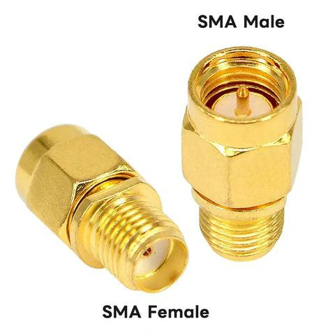
This image compares SMA male and SMA female connector structures, helping engineers and buyers identify the correct SMA interface before selecting RF connectors, adapters, or bulkhead-mounted components.
Two SMA connectors may look almost identical in a product catalog, but their mechanical purpose can be completely different.
A frequent mistake during RF component sourcing is treating all SMA interfaces as interchangeable. The front mating interface may follow the same SMA standard, but the rear structure, mounting method, and application environment determine whether the connector is suitable for the equipment.
For example, an SMA male cable connector is designed to terminate a coaxial cable, while an SMA female bulkhead connector is designed to become a fixed RF access point on an enclosure. Using one as a substitute for another may create mechanical installation problems even if the threads can connect.
Compare female, male, and bulkhead SMA structures
The SMA family includes different mechanical configurations for different RF connection tasks.
The key difference is not only the gender. Engineers also need to consider whether the connector is fixed, cable-mounted, or integrated into a device structure.
| Connector Type | Contact Structure | Mounting Method | Typical Use |
| SMA Male Cable Connector | Center pin | Cable termination | RF cable assembly connection |
| SMA Female Cable Connector | Socket contact | Cable termination | Cable-to-equipment connection |
| SMA Female Bulkhead Connector | Socket contact | Through-panel mounting | External RF equipment port |
| SMA PCB Connector | Socket or pin contact | PCB mounting | Compact RF modules |
A standard SMA male connector normally connects to a female interface. The male side contains the center pin, while the female side contains the socket contact.
The bulkhead version adds another function: mechanical fixation.
The connector is not simply hanging at the end of a cable. It becomes part of the equipment enclosure.
Why does the mounting structure matter more than the SMA thread?

This image shows the main parts of an SMA female bulkhead connector, including the threaded connector body, washer, and nut used for secure panel mounting in RF equipment and antenna systems.
This is only partially correct.
The RF interface may mate successfully, but the installation requirements can still fail.
For a bulkhead connector, engineers should check:
- panel opening diameter;
- mounting thread size;
- available rear space;
- cable exit direction;
- grounding contact area;
- sealing requirements if used outdoors.
For example, a connector installed on a thin aluminum enclosure may need a different mounting structure compared with one installed on a thick instrument panel.
A connector that is mechanically loose can introduce long-term issues:
- movement during repeated mating;
- stress transferred to the internal cable;
- unstable grounding contact;
- inconsistent RF measurements.
Understand the difference between panel mount and bulkhead mounting
The terms “panel mount” and “bulkhead” are sometimes used together, but there can be differences depending on supplier terminology.
In practical RF purchasing, both generally refer to connectors installed through an equipment wall or panel.
The main consideration is how the connector is fixed and how much mechanical support is required.
| Mounting Style | Installation Method | Suitable Application |
| Panel Mount | Fixed directly on equipment panel | General RF equipment |
| Bulkhead Mount | Passes through enclosure wall with external interface | Test ports, antenna interfaces |
| PCB Mount | Mounted directly to circuit board | Internal RF modules |
| Cable Mount | Installed at cable end | Flexible RF connection |
For OEM equipment, the mounting method should be included in the BOM.
does not tell the supplier whether the buyer needs:
- bulkhead mounting;
- PCB mounting;
- cable termination;
- waterproof structure;
- specific cable compatibility.
How Do You Select the Right SMA Female Bulkhead Connector?
Selecting an SMA female bulkhead connector usually starts with the mechanical drawing, not the product photo.
Many RF failures begin before assembly because the connector specification is incomplete.
A supplier may provide a visually similar replacement, but small differences in body length, dielectric structure, or cable termination can affect the final assembly.
Confirm connector specifications before purchase
The first step is to define the basic RF interface.
Important specifications include:
- connector gender;
- SMA interface type;
- impedance;
- frequency range;
- mounting method.
For most SMA RF applications, the impedance requirement is 50Ω.
However, impedance alone does not define whether the connector is suitable.
A complete specification should also consider:
- operating frequency;
- cable type;
- mating frequency;
- installation environment.
For example, an SMA bulkhead connector used for a GPS antenna interface may have very different requirements from one used on a microwave test fixture.
Match mechanical dimensions with installation requirements
The connector must physically fit the equipment.
Before ordering, confirm:
| Mechanical Parameter | Why It Matters |
| Mounting hole size | Determines whether the connector can pass through the panel |
| Panel thickness | Affects nut engagement and mechanical stability |
| Connector length | Determines internal clearance |
| Rear termination style | Matches cable or PCB connection |
| Cable bending space | Prevents assembly stress |
A common production issue occurs when the connector fits the front panel but the rear cable has insufficient bending space.
The result may be excessive cable stress after final enclosure assembly.
For coaxial cable assemblies, the minimum bend radius should also be considered. A small RF cable such as RG316 can tolerate tighter routing than larger semi-rigid or low-loss cables.
Verify RF specifications for the working frequency
The connector frequency rating should have enough margin above the actual operating frequency.
Practical reference:
| Frequency Margin Ratio | Application Consideration |
| ≥1.2× | General RF connection |
| ≥1.5× | Test cables and repeated measurements |
| ≥2.0× | Sensitive RF measurement applications |
This is not a replacement for actual RF testing, but it helps avoid selecting a connector that operates too close to its limit.
A connector rated for a higher frequency does not automatically make the complete assembly better. The cable type, termination quality, and connector transition design still affect the final RF behavior.
SMA Female Bulkhead Selection Checklist
Before releasing an RF connector purchase order, buyers can use the following checklist:
| Parameter | Required Information |
| Connector Gender | Female |
| Mounting Style | Bulkhead / Panel Mount |
| Impedance | 50Ω |
| Frequency Range | Maximum operating frequency |
| Material | Brass / Stainless Steel |
| Plating | Gold or specified finish |
| Cable Compatibility | RG316 / RG174 / other cable type |
| Installation | Panel thickness and hole size |
| RF Test Requirement | VSWR / Return Loss / Insertion Loss |
This information is more useful than a simple connector name because it defines the actual production requirement.
How Does SMA Female Bulkhead Design Affect RF Performance?
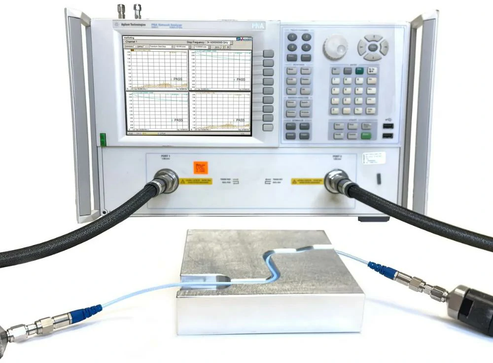
This image shows an SMA female bulkhead connector being tested with a vector network analyzer to evaluate RF performance, signal transmission, VSWR, and connector stability in high-frequency applications.
The mechanical design of an SMA connector directly affects the RF transition.
Inside the connector, the signal path changes from one transmission structure to another.
Maintain impedance matching in RF signal paths
SMA connectors are typically designed for 50Ω RF systems.
When impedance changes along the signal path, part of the RF energy reflects back toward the source.
This reflection is usually evaluated through parameters such as:
- VSWR;
- Return Loss;
- Insertion Loss.
A continuity test cannot detect these problems.
A connector may show perfect electrical connection at DC but still produce poor RF performance when measured at several GHz.
Common factors affecting RF behavior include:
- center pin alignment;
- dielectric position;
- contact quality;
- grounding structure;
- cable termination accuracy.
How Are SMA Female Bulkhead Connectors Used in RF Testing?
A test port is often used much harder than the RF port on a finished product.
During development, engineers may connect and disconnect cables repeatedly while checking antenna tuning, cable loss, or module performance. If the connector is mounted directly on a loose cable, every movement can slightly change the mechanical condition of the RF path.
That is one reason SMA female bulkhead connectors are widely used on test fixtures and laboratory equipment.
The connector is fixed to the panel, while the external SMA connection remains available for measurement cables, adapters, and antennas.
Use SMA bulkhead ports when the RF connection needs to stay repeatable
A prototype test setup is usually adjusted many times before a product design is finalized.
Engineers may replace:
- antenna modules;
- RF cables;
- matching circuits;
- filters;
- amplifiers.
If the external connection point changes position every time, comparing test results becomes more difficult.
A fixed SMA female bulkhead interface gives the test system a stable reference point.
Typical applications include:
| Application | Reason for Using Bulkhead Connector |
| Network analyzer fixture | Keeps the RF port position unchanged |
| Calibration panel | Supports repeated cable connection |
| Wireless prototype test | Provides external antenna access |
| Production inspection station | Creates a consistent test interface |
| RF module evaluation board | Simplifies measurement connection |
However, the connector itself is only one part of the measurement path.
A common mistake is upgrading the connector specification while ignoring the cable and adapter chain.
Every transition introduces a possible source of mismatch.
For higher-frequency testing, engineers normally check the complete assembly rather than judging one component separately.
Check the connector before using it as a reference point
A bulkhead connector used in a test fixture experiences conditions that are different from a normal product interface.
The connector may face:
- frequent mating cycles;
- repeated tightening;
- cable pulling force;
- accidental side loading;
- dust or contamination.
A connector can still be physically usable while the RF characteristics have changed.
Before using a bulkhead connector in a measurement fixture, common inspection items include:
| Inspection Item | Why It Matters |
| Thread condition | Prevents unstable mating |
| Center contact position | Maintains proper RF transition |
| Mounting tightness | Avoids mechanical movement |
| Connector cleanliness | Reduces contact problems |
| VSWR measurement | Confirms RF condition |
For laboratory environments, mechanical stability is not a minor detail. A small change in connector position may affect repeatability when comparing different samples.
How Should Engineers Specify Custom SMA Female Bulkhead Connectors?
Standard catalog connectors solve many applications, but OEM equipment often creates situations where a standard part is not enough.
A supplier may receive a request like:
“Need the same SMA female bulkhead connector as this photo.”
The photo may show the appearance, but it usually does not provide the information needed for production.
The missing details are often:
- mounting hole dimension;
- panel thickness;
- internal clearance;
- cable connection method;
- frequency requirement;
- inspection standard.
A connector that looks identical from the front may have a completely different rear structure.
Provide mechanical details before requesting customization
For bulkhead connectors, the mechanical drawing is usually the fastest way to avoid misunderstanding.
The supplier should receive information such as:
- panel mounting size;
- connector body length;
- fixing nut position;
- rear cable direction;
- enclosure limitations.
For example, a compact wireless device may require a short rear body because the connector is close to the PCB.
A test cabinet may have enough space for a larger structure but require stronger mechanical fixation.
The application decides the connector structure.
Define RF requirements together with mechanical requirements
A custom request should not stop at mechanical dimensions.
The electrical side should include:
- impedance;
- frequency range;
- VSWR requirement;
- insertion loss target;
- RF power requirement if needed.
A practical RF request format:
| Specification | Example |
| Interface | SMA Female Bulkhead |
| Impedance | 50Ω |
| Frequency | DC-12.4GHz |
| Mounting | Panel installation |
| Material | Brass body |
| Contact Finish | Gold plated |
| Application | RF testing equipment |
| Inspection | VSWR / continuity check |
This type of information helps suppliers evaluate the actual application instead of simply matching a catalog image.
Custom SMA Female Bulkhead Connector RFQ Information Sheet
When sending an inquiry, buyers can prepare the following information:
| Category | Information Needed |
| Connector | SMA female bulkhead |
| RF System | 50Ω or other requirement |
| Working Frequency | Maximum operating frequency |
| Installation | Panel size and thickness |
| Cable | Cable type and diameter |
| Termination | Solder / crimp / PCB |
| Environment | Indoor / outdoor / vibration |
| Testing | Required RF inspection items |
A complete RFQ normally reduces the number of sample revisions because the supplier understands the actual use condition earlier.
How Should SMA Female Bulkhead Connectors Be Tested Before Delivery?
Visual inspection is useful, but it cannot confirm RF behavior.
For RF connectors, inspection usually needs both mechanical checking and electrical verification.
Verify RF characteristics before shipment
Common RF inspection items include:
- VSWR;
- insertion loss;
- return loss;
- continuity.
Among these tests, VSWR is often used when engineers need to evaluate impedance matching.
A connector may pass continuity inspection because the center conductor is connected, but this does not mean the RF transition is working correctly at the target frequency.
For applications involving several GHz operation, a VNA test provides more meaningful information.
Check mechanical quality during incoming inspection
Bulkhead connectors also need dimensional inspection.
Recommended checks include:
| Check Point | Inspection Purpose |
| Thread size | Confirm mating compatibility |
| Mounting diameter | Confirm panel installation |
| Connector height | Confirm enclosure clearance |
| Contact position | Check assembly consistency |
| Surface condition | Prevent appearance defects |
These checks are especially important for repeat orders.
A connector that works during prototype evaluation may still create problems if production batches have dimensional variation.
SMA Female Bulkhead Connector Acceptance Checklist
| Inspection Item | Confirmation |
| SMA Female Interface | Passed |
| Bulkhead Mounting Size | Checked |
| 50Ω Impedance | Confirmed |
| Frequency Requirement | Verified |
| VSWR | Tested when required |
| Insertion Loss | Verified when required |
| Mechanical Fit | Approved |
| Appearance | Inspected |
This checklist can be used by purchasing teams and quality departments when evaluating incoming RF connector batches.
FAQ
When should a buyer choose a bulkhead version instead of a cable version?
Choose a bulkhead connector when the equipment needs a fixed external RF port, repeated connection, or panel-mounted access. Choose a cable connector when the connection point needs to move with the cable assembly.
What information should be provided when ordering a custom SMA bulkhead connector?
A supplier normally needs more than a product photo. A complete request should include SMA interface type, gender, impedance, operating frequency, mounting dimensions, cable type, termination method, material, plating, and required inspection items. Providing this information early helps avoid repeated sample adjustments caused by differences in connector length, rear structure, or cable compatibility.
What details should be included when requesting an SMA female bulkhead connector quote?
A product photo is usually not enough for an accurate quotation.
A useful RF request normally includes the SMA interface, impedance, working frequency, mounting method, cable type, termination method, and any testing requirements. If the connector is for a new device, sharing the installation drawing can help suppliers avoid selecting a part that only looks similar.
Can an SMA female bulkhead connector be used in place of a cable-mounted SMA connector?
It depends on the equipment design.
The two parts may share the same SMA mating interface, but the installation side is different. A cable connector stays with the coaxial cable, while a bulkhead connector is fixed on the housing. Before making a replacement, engineers normally check the panel opening, rear space, and cable routing first. The front connection alone does not tell if the part will work.
What should I send to a supplier when asking for an SMA female bulkhead connector?
A product picture is helpful, but it usually cannot define the whole requirement.
For a quotation or sample review, it is better to include the connector type, frequency range, cable type, mounting size, and application. If there is an existing part being replaced, a drawing or sample comparison usually saves time during communication.