
A customer once requested a replacement antenna cable for an existing wireless device. The connector looked simple: one side connected to the antenna, the other side connected to the RF module. The first sample passed the basic connection test.
The issue appeared later.
The mechanical connection was still correct, but the RF path was no longer the same as the original design. The adapter, cable length, and connector combination had changed the electrical conditions.
This type of problem is common in antenna systems. An antenna adapter is not only a mechanical converter between two connector shapes. It becomes part of the RF path.
For engineers and purchasing teams, the selection process usually starts with a simple question: “Can these two connectors mate?” However, the more useful questions are different:
- Are both sides using the same impedance?
- Is the frequency range suitable?
- Does the adapter match the cable type?
- Will the connection survive installation stress?
A correct answer requires looking beyond the connector appearance.
How Do Antenna Adapters Solve RF Interface Compatibility Challenges?
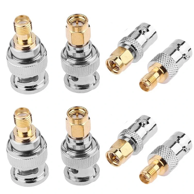
Antenna adapters are part of the complete RF signal path. Connector type, impedance, frequency range, cable compatibility, and installation environment should be considered before selecting an adapter.
Antenna systems often involve multiple components from different suppliers.
A wireless module manufacturer may select an SMA connector because the PCB space is limited. The final product enclosure may require an external antenna using an N Type connector. During production, the cable assembly becomes the bridge between these two designs.
An antenna adapter provides a practical transition between different RF interfaces.
Typical applications include:
- WiFi equipment
- GPS receivers
- LTE communication devices
- IoT wireless modules
- RF testing systems
- Antenna measurement setups
Each connection point adds a possible source of mismatch.
A common mistake during sourcing is treating the adapter as an isolated component. In reality, the adapter has to work together with the antenna connector, cable assembly, and equipment port.
For example, an SMA adapter installed on an RG316 cable and an SMA adapter installed on a thicker RG58 cable may look similar from the outside. The rear structure, cable support, and termination method can be different.
The front interface alone does not define the complete RF solution.
| Solution | Main Use | Typical Application |
| Antenna Adapter | Converts antenna interfaces | Wireless antenna connection |
| Coax Adapter | Converts coaxial cable interfaces | RF cable systems |
| SMA Adapter | Changes SMA interface configuration | RF modules and test equipment |
| RF Adapter | General RF interface transition | Communication equipment |
In laboratory environments, adapter combinations are also common. Engineers may connect equipment with different ports during measurement. However, every additional adapter introduces another interface that should be considered during RF evaluation.
A short adapter chain may work well at lower frequencies but become more sensitive when the system operates closer to the upper frequency limit.
How Do Antenna Connector Interfaces Differ?
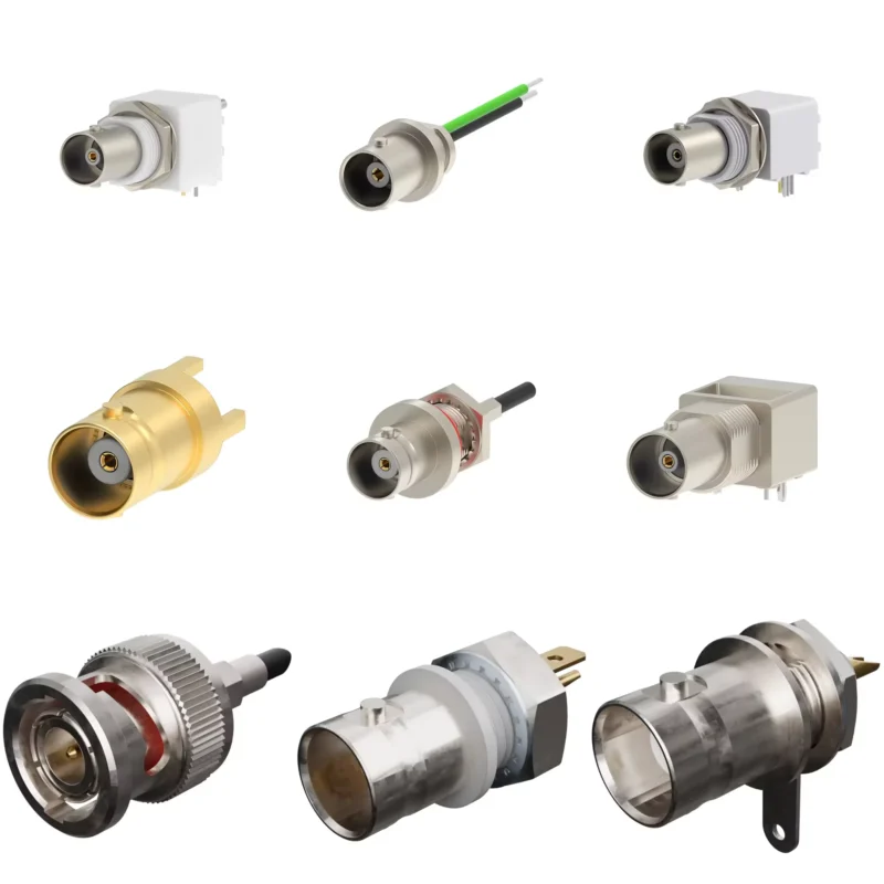
Connector selection is usually decided before the adapter is selected.
This sounds obvious, but many purchasing problems begin when the connector information in the BOM is incomplete. A description such as “antenna connector” or “RF adapter” is not enough for production.
The supplier still needs to know:
- Connector series
- Male or female interface
- Cable side connection
- Equipment side connection
- Frequency requirement
- Environmental condition
Different connector families are designed for different situations.
SMA connectors are commonly selected for compact RF devices.
They are often found in test equipment because operators can connect and disconnect them quickly.
| Interface | Mechanical Characteristic | Common Use |
| SMA | Small threaded RF interface | Wireless modules, RF boards |
| N Type | Larger threaded structure | Outdoor antennas, communication systems |
| BNC | Quick locking connection | Test instruments |
| Coax Interface | Cable transmission connection | RF cable assemblies |
The environment often decides the connector style.
A WiFi device installed inside a plastic enclosure has different requirements from an outdoor antenna mounted on a tower.
Repeated mating can wear contact surfaces. Side force from a heavy cable can stress a small connector. Tight installation spaces may create excessive bending near the adapter body.
These details are often ignored during the initial sample stage because the prototype is usually tested under ideal conditions.
Production conditions are different.
| Parameter | Check Point |
| Connector Type | SMA / N / BNC / Other RF interface |
| Gender | Male or Female |
| Impedance | Usually 50Ω for RF communication systems |
| Frequency | Must cover operating frequency range |
| Application | WiFi / GPS / LTE / RF testing |
| Environment | Indoor, outdoor, vibration, waterproof requirement |
The connector that fits mechanically is only the starting point.
The next step is confirming whether the adapter matches the RF requirements of the entire assembly. This becomes especially important when converting between compact interfaces such as SMA and larger antenna interfaces such as N Type.
How Do SMA and N Type Adapters Support Antenna Systems?
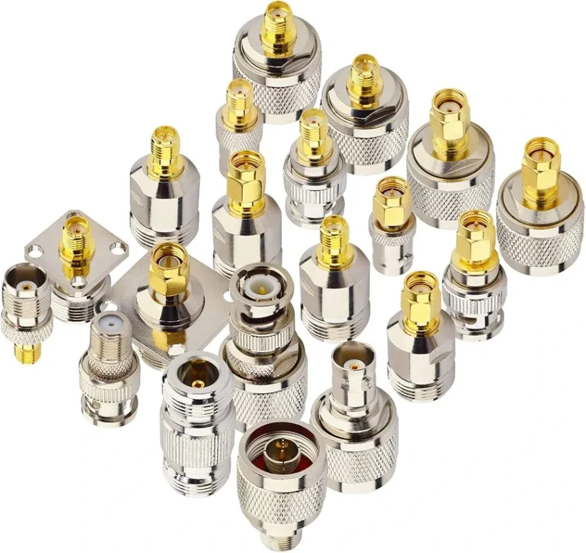
SMA and N Type connectors often appear together in antenna projects.
The reason is simple: they solve different installation problems.
N Type connectors are commonly selected for antenna-side applications where the connection may need to handle outdoor installation, repeated assembly, or stronger mechanical stress.
The adapter allows two different connector environments to work together without redesigning the entire system.
However, the adapter should not be selected only according to “SMA to N” wording.
The details still matter:
- SMA male or SMA female
- N male or N female
- Straight or right-angle structure
- Cable connection or panel mounting
- Operating frequency
- Impedance requirement
A missing gender detail is one of the most common mistakes in RF purchasing.
For example, an SMA male to N female adapter and an SMA female to N male adapter are not interchangeable, even though both are described as “SMA to N adapters”.
The connector direction must match the actual equipment ports.
| Application Situation | Possible Adapter Choice | Check Before Ordering |
| RF module to external antenna | SMA to N Type adapter | Confirm module port and antenna cable connector |
| Test equipment connection | SMA adapter combination | Check measurement frequency range |
| Outdoor antenna installation | N Type adapter solution | Check mechanical and environmental requirements |
| Cable assembly modification | Coax adapter | Confirm cable diameter and termination |
A practical sourcing note:
When an adapter is added to an existing RF assembly, check the entire connection length. A short adapter may not seem significant, but multiple adapters combined with cable length changes can affect the final measurement result.
How Does Impedance Affect Antenna Adapter Selection?
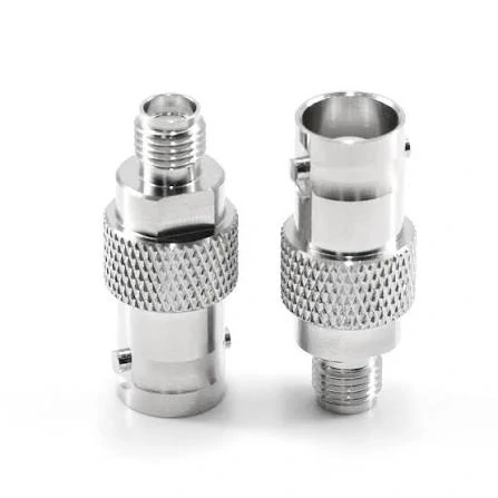
BNC antenna adapters provide a reliable connection method between different RF interfaces. They are widely used in test equipment, communication devices, and coaxial cable systems requiring quick connection.
An adapter can have the correct connector shape and still be unsuitable for the RF system.
One reason is impedance mismatch.
Most wireless antenna systems use a 50Ω RF path. This includes many SMA adapters, N Type adapters, coaxial cables, and RF test connections.
If the antenna, adapter, cable, and equipment port do not maintain the same impedance, part of the RF energy can be reflected back toward the source.
This may appear as:
- Higher VSWR
- Increased return loss
- Reduced transmitted power
- Unstable measurement results
Antenna RF Matching Check Table
| Item | Recommended Check |
| Antenna Impedance | Confirm antenna specification |
| Cable Impedance | Usually 50Ω for RF systems |
| Adapter Impedance | Match complete RF path |
| Equipment Port | Confirm interface requirement |
The adapter itself is only one part of the matching system.
A common mistake happens when replacing a damaged cable assembly. The replacement adapter may have the same connector interface, but the internal design or cable compatibility is different.
For example:
An SMA adapter designed for a small RG316 cable cannot automatically replace a part used with a larger RG58 cable. The front connector may look identical, but the rear structure and termination method may not match.
How Are Antenna Adapters Used in WiFi and GPS Applications?
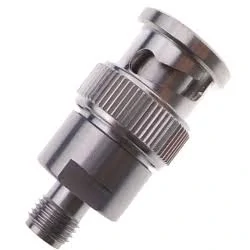
SMA and BNC RF adapters allow different connector systems to work together in antenna and measurement applications. Selecting the correct gender, frequency range, and impedance is important for stable RF transmission.
WiFi and GPS products are two common areas where antenna adapters are used.
In these applications, the connector size is often limited by the equipment design.
A small wireless device may use an internal RF connector because there is limited PCB space. During testing or final installation, engineers may need to connect an external antenna with a different interface.
The adapter provides a practical connection method.
WiFi Antenna Applications
WiFi equipment commonly uses external antennas for:
- Routers
- Wireless gateways
- Access points
- Industrial wireless devices
A WiFi antenna adapter selection should consider:
- Operating frequency band
- Antenna connector type
- Cable routing space
- Installation environment
For example, a 2.4 GHz or 5.8 GHz application may use SMA-related interfaces, but the adapter still needs to match the equipment connector and antenna cable.
The frequency range should be checked before substitution.
A connector that works at a lower frequency may not provide the same results near the upper operating band.
GPS Antenna Applications
GPS systems often use compact antenna connections.
Typical applications include:
- Navigation equipment
- Vehicle tracking devices
- Positioning modules
- Industrial monitoring systems
GPS antenna adapters are commonly used when the antenna and receiver come from different suppliers.
The important information for purchasing includes:
- Connector type
- Gender
- Cable length
- Frequency requirement
- Indoor or outdoor installation
A visual match is not enough.
A GPS adapter that fits the connector physically may still create problems if the cable type or RF specification does not match the receiver design.
How Does Frequency Range Influence Antenna Adapter Selection?
It does not.
The final RF capability depends on several factors:
- Connector design
- Manufacturing tolerance
- Contact geometry
- Dielectric material
- Adapter structure
- Assembly quality
A connector used in a DC to 6 GHz system may not be suitable for a higher-frequency measurement setup.
Reference guide:
| Ratio | Application Consideration |
| Below 1.2 | Limited margin, verify carefully |
| Around 1.5 | More practical for general RF use |
| Above 2.0 | More margin for sensitive measurement |
This is not a replacement for RF testing, but it helps during initial component selection.
A supplier receiving a request such as:
“SMA antenna adapter, 10 pieces”
still needs more information.
The next section will continue with adapter testing methods, custom RF requirements, and practical supplier communication details.
How Should Antenna Adapters Be Tested Before Installation?
A new antenna adapter usually looks acceptable when it arrives.
The connector body is clean. The threads engage smoothly. The mating parts fit without obvious problems.
That is also the stage where many problems remain hidden.
A visual inspection can confirm machining issues, plating damage, missing parts, or incorrect interfaces. It cannot confirm how the adapter behaves once RF signals pass through it.
For prototype work, a simple connection check may be enough. Production applications normally require more attention because the adapter becomes part of every assembled unit.
The inspection method depends on where the adapter is used.
A basic incoming inspection may include:
| Inspection Item | What to Check |
| Interface | Correct connector series and gender |
| Mechanical Fit | Thread engagement and locking condition |
| Contact | Center pin position and contact stability |
| Appearance | Scratches, deformation, plating condition |
| RF Test | VSWR, return loss, insertion loss when required |
One detail worth mentioning: continuity testing is useful, but it has limits.
A multimeter can confirm that two points are electrically connected. It cannot show whether the RF impedance is correct or whether the adapter creates additional reflection.
A low-frequency prototype may continue working even when the connection is not ideal. A measurement system operating near the upper frequency range is less forgiving.
How Do Engineers Prepare Specifications for Custom Antenna Adapters?
Many custom adapter projects do not start because a special connector is required.
They start because an existing assembly cannot fit the final product.
A device enclosure changes. The antenna position moves. A cable route becomes different from the prototype. The original adapter no longer works.
At this point, suppliers usually need more than a product photo.
A useful RF specification should describe the connection from both sides.
Example:
| Specification Field | Information Needed |
| Interface A | SMA / N Type / BNC / Other |
| Interface B | SMA / N Type / BNC / Other |
| Gender | Male / Female |
| Impedance | 50Ω or other requirement |
| Frequency Range | Working frequency |
| Cable Requirement | Type and length if applicable |
| Installation | Panel mount, cable mount, equipment connection |
| Quantity | Sample or production quantity |
This avoids a common situation: the first sample can be assembled, but it does not match the final production condition.
For antenna-related products, mechanical information is often as important as electrical information.
A supplier should know:
- Is the adapter installed inside an enclosure?
- Is the cable frequently moved?
- Is the connection exposed outdoors?
- Is there limited space around the connector?
For example, a straight adapter may work on a laboratory bench but create excessive bending force when installed close to a panel wall.
How Can Buyers Avoid Common Antenna Adapter Sourcing Problems?
Most sourcing problems happen before production begins.
The issue is usually incomplete information rather than manufacturing difficulty.
A purchase request saying:
“Need antenna adapter, SMA type.”
leaves several unanswered questions.
The supplier still needs to know:
- Which SMA interface?
- Male or female?
- What is the other side?
- What frequency will be used?
- Is it for antenna connection or test equipment?
- Does the customer have cable requirements?
A clearer request reduces communication cycles.
This type of information is useful for engineering review and quotation.
Another point often missed by buyers is adapter quantity inside the RF path.
One adapter may have little influence in a system. Several adapters connected together create additional interfaces.
A test setup with multiple transitions may show different results compared with the final product assembly.
Antenna Adapter Risk Check Table
| Situation | Possible Issue | Recommended Review |
| Only connector appearance checked | Wrong interface selected | Confirm complete specification |
| Sample works but production fails | Assembly condition changed | Review cable length and routing |
| Signal changes after adding adapter | Additional mismatch point | Check RF path |
| Outdoor installation | Mechanical damage risk | Review environment requirement |
| High-frequency application | Insufficient margin | Confirm test requirement |
The adapter should match the actual working condition, not only the drawing.
FAQ
Does an antenna adapter affect RF signal loss?
Yes. Every additional connection introduces another RF transition. The actual influence depends on adapter design, frequency, assembly quality, and the rest of the RF path.
Can I use an SMA adapter for a GPS antenna?
It depends on the GPS equipment interface and antenna cable specification. The connector size alone does not determine compatibility.
Why does the adapter impedance need to match the antenna system?
Most RF communication systems use a controlled impedance path, commonly 50Ω. A mismatch can increase reflection and affect signal stability.
Should antenna adapters be tested with a VNA?
For basic applications, standard inspection may be enough. For high-frequency systems, test equipment such as a VNA can provide additional information about VSWR and return loss.
Practical Notes Before Ordering Antenna Adapters
An antenna adapter request usually looks simple from the purchasing side.
From an RF perspective, it is a small part inside a larger system.
The connector interface, cable, antenna, equipment port, and installation environment all influence the final result.
Providing the operating frequency, connector combination, cable information, and application details before quotation helps suppliers evaluate the correct structure faster.
