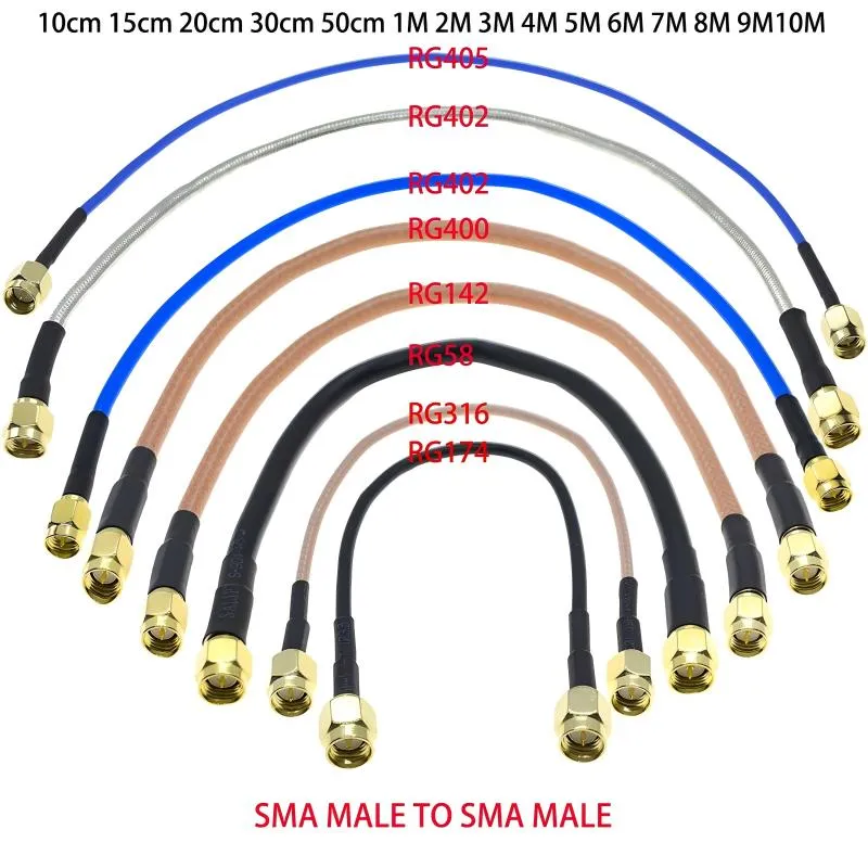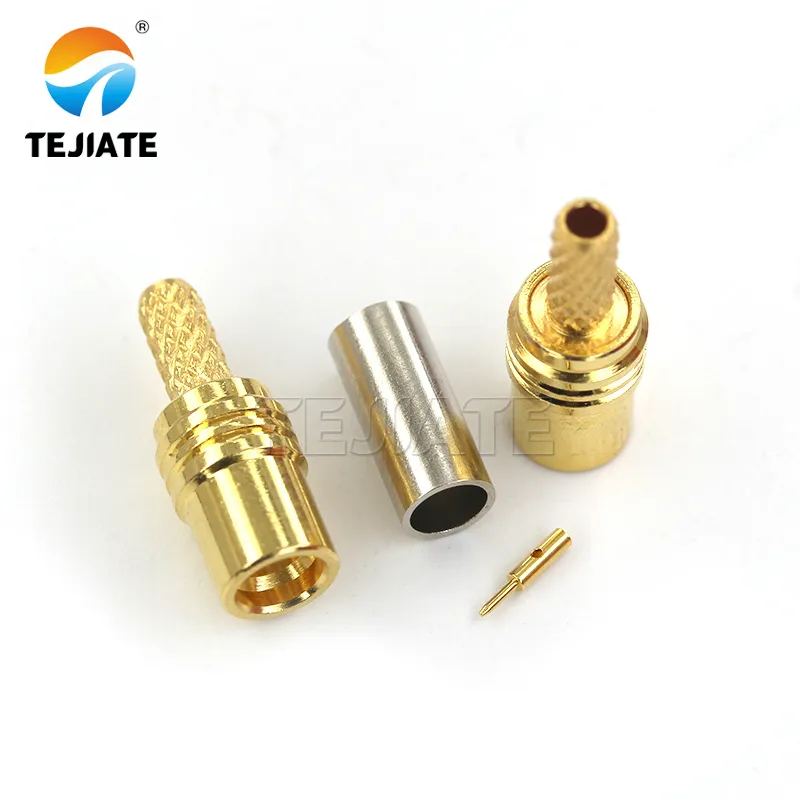
SMA RF Cable Selection and Application Guide
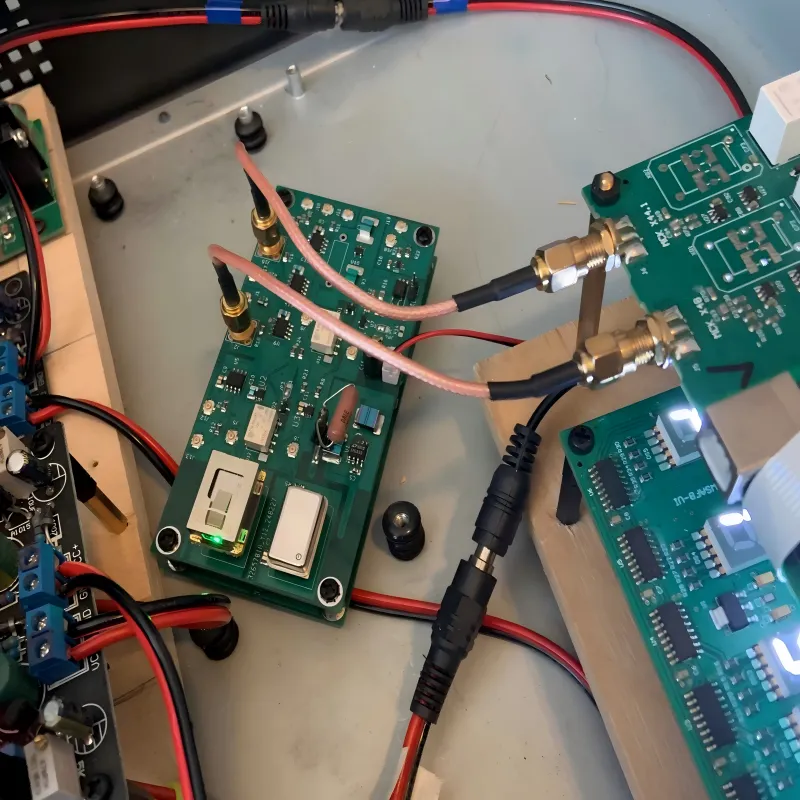
In RF systems, cables almost never get blamed first. When a link underperforms, engineers tend to look at the radio, the antenna, or firmware settings. The sma rf cable sitting between them is usually treated as background hardware—something passive, assumed stable, and rarely questioned.