
A cable can arrive with the correct connectors on both ends and still be wrong for the job.
This usually shows up after the sample leaves the purchasing desk. The SMA end mates. The N-Type end mates. Continuity is fine. Then the engineer installs the cable and finds that the right-angle connector points toward the enclosure wall, the cable is too stiff for the available route, or the measured loss is higher than expected at the top of the operating band.
None of those problems are unusual.
Most start with an RFQ that describes the part too loosely.
“500 mm SMA to N cable” may be enough to start a conversation. It is not enough to control production.
For RF cable assemblies, the useful specification is the one another person can pick up six months later and build again without guessing. That means fixing the interfaces, cable, length reference, RF limits, and the few mechanical details that actually affect installation.
Which Assembly Requirements Must Be Defined Before RFQ?
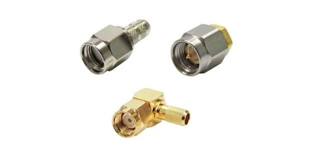
Different SMA RF connector configurations can be selected for custom RF cable assemblies based on cable type, installation space, connector orientation, and equipment interface requirements.
Do not start with the cable model.
Start with the two things that cannot be changed easily: the equipment ports.
Identify the Two Fixed Equipment Interfaces
Assume one side of the system already has an SMA female connector on a radio module and the other side connects to an N-Type antenna port. That immediately narrows the assembly, but several details are still open.
Is the SMA standard polarity or reverse polarity?
Does the cable need to exit straight out of the module, or turn immediately because the enclosure is shallow?
Is the N-Type connection outside the enclosure?
Is one end panel-mounted?
These questions sound mechanical, but they affect the RF assembly that can actually be produced.
A common mistake is to identify connectors from a photograph and stop there. Photos are useful for screening obvious differences. They are poor substitutes for a drawing, equipment part number, or mating-interface confirmation when polarity or mounting style is uncertain.
The distance between the ports also needs care.
A buyer may measure 300 mm from point A to point B and order a 300 mm assembly. Once the cable is routed around a fan, bracket, battery pack, or PCB edge, 300 mm is no longer enough.
Measure the route the cable will follow, not the empty space between the ports.
Separate Electrical Requirements From Mechanical Constraints
RF requirements and installation requirements often pull in opposite directions.
A larger low-loss cable may look better on paper because attenuation is lower. Inside a compact enclosure, the same cable may be difficult to bend without loading the connector.
A thinner cable solves the routing problem, but now the loss at 3 GHz or 6 GHz may be higher than the link budget allows.
That is the real trade-off.
For the electrical side, record the operating frequency, impedance, expected insertion-loss limit, and any VSWR or return-loss requirement that matters to the project.
For the mechanical side, record cable length, cable diameter limits, connector direction, routing space, bend restrictions, and whether the assembly will stay fixed or move during use.
Do not mix these into a vague note such as “low loss, flexible cable required.” That wording leaves too much room for interpretation.
A better RFQ explains which limit is actually controlling the design.
That gives the supplier something useful to work with.
If the cable family itself is still open, RG316, RG58, RG142, and low-loss alternatives should be compared against the actual frequency, length, OD, shielding, and bend requirement rather than ranked as “better” or “worse.”
Prototype, Replacement, or Production Part
These are not the same buying job.
A prototype can tolerate some open points because the sample is being used to answer questions. Does it fit? Is the cable flexible enough? What does S21 look like after installation? Does the connector orientation make sense?
A replacement cable is different. The physical match may matter more than improving the design. If the old assembly has a fixed panel interface, special routing, or a defined installed length, changing one “minor” detail can create a new problem.
Production parts need tighter control again.
Once the sample is approved, the buyer should know which connector part numbers, cable construction, termination method, drawing revision, and inspection conditions are being repeated. Otherwise a reorder can quietly become a slightly different assembly.
That is where many sourcing arguments begin: the supplier believes the replacement is equivalent; the customer expected the original build to be frozen.
Define the Intended Operating Environment
A bench cable has an easier life than a cable installed next to a moving hinge.
That difference belongs in the RFQ.
For a fixed indoor assembly, basic cable routing and temperature may be enough. A test lead may need repeated flexing. An outdoor antenna assembly may need attention to moisture, UV exposure, sealing, and connector protection. Equipment exposed to vibration may need additional strain relief or retention checks.
Do not add environmental requirements simply because they sound safer. Add the ones the assembly will actually see.
Unnecessary requirements increase cost and can reduce the number of workable cable constructions.
How Should Connector A and Connector B Be Specified?
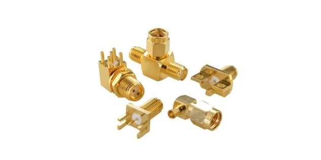
SMA connectors are available in multiple mounting, orientation, and interface configurations. Selecting the correct connector interface, gender, polarity, and mounting style is important when specifying an RF cable assembly.
Record Interface, Gender, and Polarity Separately
The mating interface comes first. Gender comes next. Polarity is a separate item where applicable.
This matters most with SMA and RP-SMA because people often identify the connector by thread direction or by the center contact alone. That shortcut can fail.
Do not assume that a connector which screws together is electrically the intended interface.
The same caution applies when 50-ohm and 75-ohm versions exist within a connector family. Mechanical similarity is not enough reason to treat them as interchangeable.
Straight, Right-Angle, or Bulkhead
Connector direction is usually decided by available space, but it should be shown on the drawing.
A right-angle connector can solve a shallow-depth problem. It can also point the cable into the wrong side of the enclosure.
If orientation matters, “right angle” alone is incomplete.
Bulkhead versions need more information. Panel thickness, washer and nut arrangement, mounting side, and cable exit direction may all affect fit.
For custom work, a marked-up equipment photo is sometimes more useful than a long email. A simple arrow showing the required cable exit can prevent a sample remake.
Match the Rear Body to the Cable
This is where visually similar connectors stop being interchangeable.
An SMA cable plug intended for RG316 is not automatically suitable for RG58. The front mating interface may be identical, but the rear body, ferrule, center contact, dielectric support, and stripping dimensions can be different.
If the cable OD does not match the connector hardware, the assembly may still be possible to build. That does not mean it is a controlled build.
Loose ferrules, poor braid contact, an incorrectly positioned center pin, or excess solder near the dielectric can all create problems later.
So before releasing the first drawing, confirm both ends against the actual cable construction.
Not just “SMA to N.”
Not just “50 ohm.”
The assembly needs to be treated as one part.
Which Cable Construction Fits the RF and Mechanical Limits?
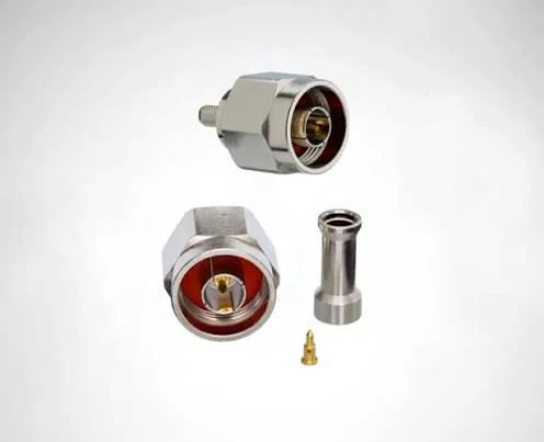
N Type RF connectors are commonly used with coaxial cable assemblies for antenna, communication, and RF equipment connections. Connector rear dimensions and termination structure should match the selected coaxial cable.
A cable that works well on a test bench may be a poor fit inside a compact enclosure.
The problem is not always attenuation. Sometimes the cable is simply too stiff. The technician has to force it around a corner, and the strain ends up at the connector. The assembly may pass its initial electrical test, yet its installed condition is quite different from the one tested.
Cable construction needs to be settled before the connector termination is approved.
Compare Flexible, Semi-Flexible, and Semi-Rigid Cable Construction
Flexible coaxial cable is generally easier to route around brackets and equipment housings. It is often used for internal connections, antenna jumpers, and assemblies that need occasional repositioning.
Semi-flexible cable offers a different compromise. It can retain a formed shape better than many conventional flexible cables, although repeated bending may not be suitable for every construction.
Semi-rigid cable is useful where a precisely formed RF path is required. Once shaped, it is normally intended to remain in that configuration. Repeated bending can damage the outer conductor or alter its electrical characteristics.
For a fixed microwave module, a formed semi-rigid assembly may be appropriate. For a serviceable enclosure where the cable must move whenever the cover is opened, it could create unnecessary maintenance problems.
Check the manufacturer’s bend-radius limits, including any distinction between installation bending and repeated flexing.
Evaluate RG316, RG58, RG142, and LMR-Type Cables by Requirement
These cable families are often compared during RF cable assembly sourcing, but their names alone do not establish which one is suitable.
| Cable | Practical consideration | Check before approval |
| RG316 | Small diameter, relatively easy routing | Attenuation at required length |
| RG58 | Common general-purpose coaxial construction | Frequency-dependent loss and available space |
| RG142 | PTFE-based construction with dual shielding | Stiffness, diameter, and termination fit |
| LMR-type | Various low-loss constructions | Exact model, bend limits, and connector compatibility |
A 150 mm RG316 jumper and a 3 m RG316 jumper should not be judged by the same loss expectation.
Likewise, an LMR-type cable may offer lower attenuation over a long run but require more room behind the connector.
If the application calls for a low loss cable assembly, calculate the expected loss at the actual frequency and length. Do not select cable solely because the product description contains the words “low loss.”
Verify the Cable Datasheet Before Connector Termination
The connector’s rear dimensions must match the cable being purchased.
Check the center conductor diameter and construction, dielectric diameter, shield arrangement, and overall jacket diameter. Solid and stranded center conductors may also require different contact or termination arrangements.
This is particularly relevant when an approved cable is replaced with an apparently equivalent alternative.
Even where two cables share the same nominal impedance and outer diameter, their internal dimensions may differ.
A cable substitution should trigger a compatibility check before the existing connector hardware is reused.
How Should Length and Tolerance Be Controlled in Production?
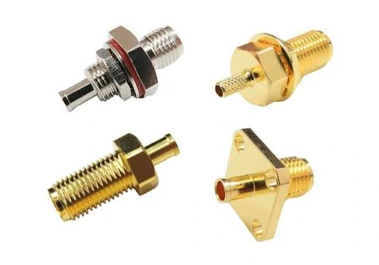
RF coaxial connectors with different mounting and termination structures can be used in custom cable assemblies. Connector body dimensions, cable compatibility, installation direction, and mounting requirements should be confirmed before production.
A customer orders 500 mm cables. The first batch arrives, and several assemblies appear shorter than expected.
The supplier measured from one connector reference point. The customer measured the complete assembly from end to end.
Both measurements may be internally consistent. The problem is that the drawing never stated which measurement controlled acceptance.
Define Whether Length Means Overall Assembly or Cable Cut Length
Three dimensions are commonly confused: the cable’s cut length, the finished assembly’s overall length, and the distance between specified connector reference planes.
They are not interchangeable.
A straight SMA-to-SMA cable can be relatively straightforward to measure. Add a right-angle connector or a bulkhead termination, and the measurement reference becomes more important.
The approved drawing should show the reference points clearly.
For assemblies with angled connectors, include orientation dimensions where required. A length dimension alone may not describe the installed geometry.
Establish Length Tolerance From the Installation Requirement
Avoid assigning ±5 mm to every assembly simply because it is convenient.
A short internal jumper installed between two fixed PCB connectors may need closer dimensional control than a long cable routed through an open equipment rack.
But a tighter tolerance is not automatically better.
It may increase cutting, assembly, and inspection costs without improving the final installation.
The tolerance should reflect the available routing allowance, connector geometry, and assembly process capability.
Account for Connector Body Length and Cable Routing
A cable cut to 300 mm does not necessarily produce a finished assembly measuring 300 mm.
Connector construction and termination geometry affect the relationship between cut length and finished length. That relationship must be established for the approved connector-and-cable combination.
For a first article, check the finished length, connector orientation, and installation fit against the controlled drawing.
Do this before approving a large production quantity. Discovering a dimensional misunderstanding after several thousand assemblies have been terminated is an expensive way to clarify a drawing.
How Can RF Loss and Matching Limits Be Written Into the Specification?
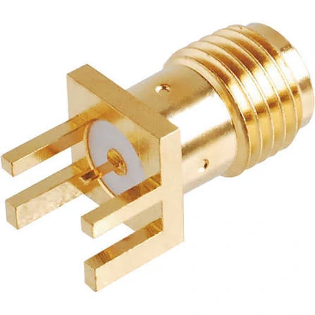
SMA PCB mount RF connectors provide a compact interface between RF circuits and external coaxial connections. Mechanical dimensions, impedance, frequency requirements, and mating interface should be confirmed during RF assembly design.
“Low insertion loss” is not an acceptance criterion.
It tells the supplier what the buyer wants, but not what a finished assembly must achieve.
Include Connector and Transition Loss in the Budget
The finished RF path includes two connector terminations and potentially additional adapters.
This is an engineering estimate, not a substitute for measurement. Reflections, connector transitions, and the test reference planes can affect the measured insertion loss.
A continuity test cannot reveal these RF effects.
Specify VSWR or Return Loss Across the Required Band
An assembly may show acceptable insertion loss at one frequency and poor matching elsewhere.
Specify the operating band and the required VSWR or return-loss limit. A statement such as “VSWR ≤ 1.5 from DC to 6 GHz” is meaningful only if the selected cable, connectors, and measurement method can support that requirement.
For a microwave cable assembly, additional checks may be needed for phase stability, flex sensitivity, or repeatability after connector mating.
Those requirements should come from the application rather than being added to every RF cable order.
Which Termination and Inspection Methods Should Be Approved?
A connector can be the correct model and still be assembled badly.
That is why the termination method belongs in the controlled build, especially once a sample has been approved.
Crimp, solder, and clamp terminations are not interchangeable manufacturing preferences. The connector design and cable construction normally determine which process makes sense.
With a crimp-style connector, ferrule size and crimp tooling matter. A ferrule that is slightly oversized may hold during handling but provide poor shield retention. Excessive crimp force can damage the dielectric.
Soldering has a different risk. Too much heat can soften or deform the dielectric, move the center conductor, or leave excess solder where the geometry should remain controlled.
Check More Than Continuity
Basic electrical inspection should confirm:
- center conductor continuity
- shield continuity
- no short between center and shield
Useful, but not enough.
A cable can pass all three checks and still show poor return loss at the operating frequency.
Before production release, inspect the strip dimensions, center-contact position, braid contact, ferrule condition, and visible dielectric damage. Where pull force or cable retention matters, define the acceptance method instead of relying on an operator’s judgement.
Tooling changes also deserve attention.
If the supplier changes the crimp die, stripping tool, connector source, or cable supplier, the approved assembly may need another engineering check. A production line can produce a physically similar part with a different RF result.
How Should Prototype and Batch RF Testing Be Planned?
First-article testing and production testing solve different problems.
The first article asks, “Does this design actually work?”
Routine production testing asks, “Are we still building the same thing?”
For the first sample, check dimensions, connector orientation, workmanship, continuity, and RF response across the required frequency band.
A VNA measurement of S11 and S21 is useful when insertion loss and matching are part of the acceptance criteria.
The setup matters.
Calibration reference planes, test adapters, connector condition, and cable movement can all influence the result. If a limit is tight, record how the measurement was taken rather than sending a screenshot with no test context.
For cables used in moving equipment or repeated test work, it may also be worth checking RF performance after controlled bending.
Not every production order needs 100% VNA testing.
A short, low-risk assembly may use dimensional and continuity checks with periodic RF sampling. A microwave cable used in a critical test path may justify much tighter inspection.
The decision should come from project risk, not from habit.
How Can Buyers Build a Complete RF Cable Assembly RFQ?
A good RFQ reduces the number of assumptions made before the sample is built.
The following matrix is useful for both engineering and purchasing teams.
| Specification field | Buyer input | Supplier confirmation |
| Connector A | Family, gender, polarity, orientation | Exact part number |
| Connector B | Family, gender, polarity, orientation | Exact part number |
| Cable | Approved model or required characteristics | Exact cable model |
| Impedance | 50Ω / 75Ω / specified | Compatible system |
| Length | Nominal finished length | Measurement reference |
| Tolerance | Installation requirement | Achievable tolerance |
| Frequency | Operating band | Qualified range |
| Insertion loss | Maximum allowed at frequency | Test limit |
| VSWR / return loss | Required limit | Test method |
| Environment | Temperature, flexing, moisture, vibration | Suitable construction |
| Quantity | Samples and production volume | MOQ / production plan |
| Inspection | Sampling or 100% | Agreed inspection scope |
This is more useful than a long email because missing fields are visible immediately.
RF Cable Assembly Specification Completeness Score
Count ten core inputs:
- Connector A
- Connector B
- Cable model
- Impedance
- Length and tolerance
- Operating frequency
- RF acceptance limits
- Mechanical or environmental requirements
- Prototype and production quantity
- Drawing and inspection requirements
If a field genuinely does not apply, mark it N/A and remove it from the denominator.
The score is not an industry certification. It is simply a practical RFQ review tool.
A low score usually means the supplier is being asked to make engineering decisions that should belong to the buyer.
How Should Custom RF Cable Assemblies Be Released for Repeat Orders?
Repeat orders should become easier, not restart the engineering discussion.
Freeze the approved BOM and drawing revision.
That means fixing the connector part numbers, cable model, finished length, tolerance, termination process, and any RF acceptance limits that were used for the approved sample.
Change control matters here.
A cable supplier change may appear minor to purchasing, but it can alter OD, attenuation, braid construction, or stripping dimensions.
The same applies to connector substitutions.
If a supplier proposes an “equivalent,” ask what actually changed.
Labels and packaging should also be included in the approved configuration where traceability matters. Batch number, drawing revision, cable identification, and test records can save a lot of time when a later production issue has to be investigated.
For repeat purchasing, reference the approved drawing rather than rewriting the product description from memory.
“Same as last order” is convenient.
A drawing revision is safer.
FAQ
Does every RF cable assembly need VNA testing?
No. Inspection should match the application risk and customer requirement. Continuity may be enough for some low-risk assemblies, while microwave or tightly controlled RF paths may need S11 and S21 testing.
Can RG316 be replaced with another 50-ohm cable?
Not automatically. Check attenuation, OD, dielectric dimensions, shield construction, bend behavior, and connector compatibility before approving a substitute.
Why can a cable pass continuity but fail at RF?
Continuity only confirms a conductive path. It does not detect excessive insertion loss, impedance discontinuities, poor matching, or frequency-dependent termination problems.
Should cable length be measured connector-to-connector?
Only if the drawing defines it that way. The measurement reference must be stated clearly, particularly for right-angle and bulkhead assemblies.
What information should be sent for a custom RF cable assembly quotation?
At minimum, provide both connector interfaces, cable requirement, impedance, finished length, operating frequency, quantity, and any critical RF or mechanical limits.