
The connectors appear to fit, the coupling feels secure, and the equipment powers up normally. Yet the measurement changes after the adapter is installed.
The immediate assumption may be that the adapter is defective. Sometimes it is. Other times, the problem comes from an incorrect connector configuration, an overlooked impedance difference, or an adapter that was never specified for the operating frequency.
This is a common problem when RF components are selected from product photos or shortened purchasing descriptions.
A coax adapter should be selected around the two interfaces already installed in the system, not simply around the connector names appearing in a catalog. The mating geometry must be correct, but so must the electrical and mechanical requirements.
For engineers and buyers, the practical starting point is straightforward: identify both existing ports, determine exactly how they must mate, and record the conditions under which the connection will operate.
Which Two RF Ports Must the Adapter Connect?
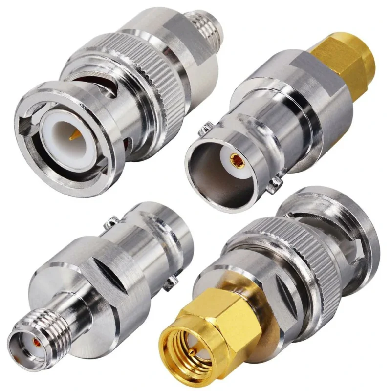
An adapter order often begins with a brief request: “We need an SMA-to-BNC adapter.”
That description identifies two connector families, but it is not enough to release a purchase order. It says nothing about the gender at either end, the impedance, the required orientation, or the available mounting space.
A proper selection begins with the equipment, not the adapter.
Identify the Existing Equipment Port Before Choosing the Adapter
Examine the actual connector fitted to the instrument, enclosure, antenna, or cable assembly.
The connector may be mounted directly to a PCB, secured through a panel, or attached to a flexible coaxial cable. These configurations place different mechanical demands on the adapter.
A panel-mounted N-Type connector may tolerate an installation arrangement that would be unsuitable for a small PCB-mounted SMA port. Even if the connector interfaces mate correctly, the additional weight and leverage of a rigid adapter can create mechanical stress.
Port identification should therefore include more than the RF connector series.
Look at the coupling mechanism, center contact, mounting arrangement, and available clearance. For unfamiliar interfaces, compare these details with the manufacturer’s mechanical drawing rather than relying on appearance alone.
Record Both Mating Interfaces Independently
Treat each existing port as a separate engineering input.
A useful example is a test setup with an SMA female output on one instrument and a BNC female input on another device.
If a rigid adapter is appropriate for the installation, the required adapter interfaces are SMA male and BNC male. This identifies the mating arrangement, although impedance, frequency rating, and mechanical suitability still require confirmation.
A simple recording format prevents confusion:
| Verification item | Equipment Port A | Equipment Port B |
| Connector family | SMA | BNC |
| Existing gender | Female | Female |
| Polarity | Standard | Standard |
| System impedance | 50 Ω | 50 Ω |
| Mounting | Panel-mounted | Panel-mounted |
| Required adapter end | SMA male | BNC male |
This is a mating example, not a universal recommendation. The actual installation may require a cable assembly rather than a rigid adapter.
For purchasing teams, documenting both ports is especially helpful when a drawing, quotation, and supplier product title use different naming conventions.
Separate Same-Series Couplers From Cross-Series Transitions
Not every coaxial adapter changes connector families.
An SMA female-to-female coupler can join two compatible SMA male interfaces. An SMA-to-N adapter, by contrast, changes the mating connector series while maintaining the intended coaxial signal path.
The distinction affects sourcing.
Same-series couplers are often used for connection extension or gender conversion. Cross-series adapters solve compatibility problems between different connector interfaces.
Neither arrangement should be assumed electrically transparent. Every additional RF interface introduces potential reflection and insertion loss, particularly as operating frequency increases.
Confirm the Adapter’s Actual Mating Ends
One purchasing detail causes repeated errors: the stated connector gender may describe the equipment port rather than the adapter itself.
If a buyer requests an adapter “for an SMA female port,” the supplier still needs to establish that the required mating end is SMA male.
The safest RF purchasing description identifies the physical ends of the adapter directly.
For example:
SMA male to BNC male RF adapter, 50 Ω, straight configuration, with frequency rating and mechanical dimensions to be confirmed.
That description is substantially more useful than “SMA/BNC converter.”
How Do You Verify Gender and Polarity Before Mating?
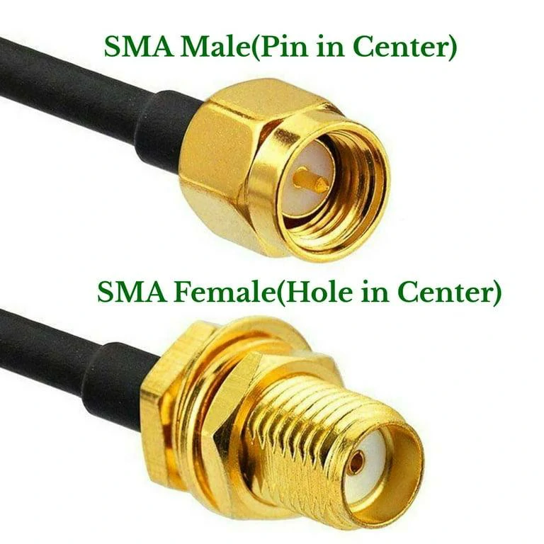
This comparison shows standard SMA male and female coaxial connectors. The SMA male interface has a center pin, while the SMA female interface has a center socket. Verify both the outer coupling structure and center contact before selecting an RF adapter.
Two adapters can carry almost identical descriptions while having incompatible mating interfaces.
The problem becomes more noticeable with SMA and RP-SMA configurations, where the outer coupling structure alone does not reliably identify the electrical interface.
Before ordering a coaxial connector adapter, verify both the outer coupling arrangement and the center contact.
Check the Outer Coupling and Center Contact Together
Connector gender is not determined by the center pin alone.
For standard SMA connectors, the male interface normally has an internally threaded coupling nut and a protruding center pin. The female interface has external threads and a center socket.
These mechanical differences mean the inspection method must follow the relevant connector family.
A close-up photograph should show the entire mating face, including the coupling mechanism and center contact. Side-view product images alone are often insufficient.
Identify Reverse-Polarity Interfaces Before Selecting an SMA Adapter
RP-SMA deserves separate attention because its center-contact arrangement differs from standard SMA.
A standard SMA male normally contains a center pin. An RP-SMA male uses a center socket, while retaining the male-style coupling arrangement.
Likewise, an RP-SMA female uses a center pin instead of the socket found in a standard SMA female.
This difference is easy to miss when purchasing from small product thumbnails.
A standard SMA adapter and an RP-SMA adapter should never be treated as interchangeable merely because their threaded sections appear compatible. An incorrect combination can prevent proper contact or damage the center interface.
Match Male-to-Male, Male-to-Female, and Female-to-Female Configurations
Gender conversion depends on the existing connection, not on a preferred adapter style.
A coax male to male adapter is useful when both existing interfaces require male mating ends. A coax male to female adapter can extend or transition between complementary connector configurations. A female-to-female coupler may be appropriate when connecting two compatible male cable ends.
These descriptions must also identify connector series and polarity.
For instance, “male-to-female” does not establish whether the product is SMA-to-SMA, SMA-to-BNC, or another combination.
Use Drawings When Connector Naming Is Ambiguous
For prototype development or repeat production, photographs are useful but should not replace controlled interface dimensions.
Request a mating-interface drawing when there is uncertainty about center-contact geometry, coupling threads, interface depth, or mechanical tolerances.
This becomes particularly relevant when an adapter must connect to an existing enclosure where the connector is recessed or surrounded by other components.
A mechanically compatible connector can still be impossible to tighten in the installed position.
Record the approved mating configuration and drawing revision before releasing a production order. That small step helps prevent an apparently equivalent replacement from introducing an unexpected fit problem.
How Should 50Ω and 75Ω Compatibility Be Checked?
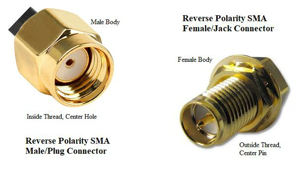
This image illustrates reverse-polarity SMA (RP-SMA) male and female connectors. The RP-SMA male interface uses a center socket, while the RP-SMA female interface uses a center pin. Confirm connector polarity and mating geometry before ordering an SMA adapter for wireless equipment or antenna systems.
A coax adapter may screw together perfectly and still be the wrong electrical part.
This happens most often when buyers focus on connector family and overlook impedance. BNC is a good example. Both 50Ω and 75Ω versions exist, and some combinations may appear mechanically similar enough to create confusion during sourcing.
The first question should be simple: what impedance is the RF path designed around?
Confirm the Reference Impedance of Both RF Systems
Most RF communication, antenna, test, and wireless systems use 50Ω interfaces. Many broadcast and video systems use 75Ω.
The adapter should normally match the reference impedance of the equipment, cable, and surrounding RF path.
Do not assume that a connector marked “BNC” or “N-Type” tells you everything needed. The connector family identifies the interface style. It does not automatically establish the impedance of every version sold under that name.
A practical verification table can prevent a surprising number of purchasing errors:
| RF path item | Parameter to confirm | Typical sourcing risk |
| Equipment Port A | 50Ω or 75Ω | Datasheet not checked |
| Equipment Port B | 50Ω or 75Ω | Similar-looking connector assumed compatible |
| Coax cable | Nominal impedance | Cable substituted during assembly |
| Coax adapter | Rated impedance | Selected only by connector name |
| Final RF path | VSWR / return loss | Mechanical fit treated as electrical approval |
The important point is that the adapter is one component in a complete transmission path. Checking it in isolation is not enough if the cable or equipment interface has already introduced an impedance change.
Distinguish Mechanical Mating From Electrical Matching
Those are not the same test.
A mechanically mating transition can create a discontinuity in characteristic impedance. The practical result may be increased reflection, poorer return loss, or a VSWR shift that becomes more obvious toward the upper end of the operating band.
Continuity testing will not reveal this problem.
A multimeter may confirm that the center conductor and outer conductor are electrically continuous while the adapter still performs poorly at RF frequencies.
Avoid Treating a Standard Adapter as an Impedance Transformer
A normal coaxial adapter should not be treated as an automatic 50Ω-to-75Ω impedance converter.
Its primary function is usually interface transition, gender conversion, or geometry change.
If a system genuinely requires a transition between different impedance environments, the design may require a dedicated matching network, transformer, or another verified RF solution.
That requirement belongs at system level, not in a vague purchase description such as “50 to 75 ohm adapter.”
Which Adapter Geometry Fits the Installed Equipment?
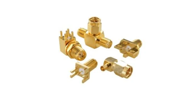
This image shows assorted SMA RF connectors with different mounting styles and orientations, including straight, right-angle, and PCB-mount configurations. Selecting the appropriate SMA connector requires checking the mating interface, mounting method, installation clearance, and RF application requirements.
The shortest adapter is not automatically the safest installation.
A rigid coax adapter changes the mechanical load applied to the equipment port. Length, orientation, connector diameter, wrench clearance, and the cable connected to the opposite end all matter.
Compare Straight and Right-Angle Configurations by Port Clearance
A straight adapter works well when the mating axis is accessible and the connected cable can exit without an aggressive bend.
A right angle coax adapter may be more suitable inside a compact enclosure or behind rack-mounted equipment where straight cable clearance is limited.
But a right-angle body also changes the loading direction.
If a heavy cable hangs from the adapter, the equipment connector can experience a bending moment rather than a mostly axial load. This deserves particular attention with small PCB-mounted SMA ports.
Space must therefore be evaluated around the complete installed assembly, not from the adapter drawing alone.
Check Coupling Nut and Tool Access
A drawing can show that the adapter body physically fits between two components while hiding a more basic problem: nobody can tighten it.
Threaded SMA, TNC, and N-Type interfaces need adequate access around the coupling area. Depending on the installation, operators may require finger clearance or wrench access.
This matters in production.
A prototype assembled carefully on an open bench may work, while the same adapter becomes difficult to install after nearby PCB assemblies, covers, or brackets are fitted.
That type of assembly problem is better caught during mechanical review than on the production line.
Evaluate Bulkhead and Panel-Mount Transitions
When an adapter passes through an enclosure wall, check more than the connector series.
Panel thickness, thread length, mounting nut position, washer arrangement, anti-rotation features, and available internal clearance can all affect fit.
If the connector is expected to carry cable load, mechanical support becomes even more important.
A panel transition should not be approved simply because the RF interfaces mate.
How Do Frequency and Added Interfaces Affect RF Results?
A connector family may have a familiar industry frequency range, but that does not guarantee that every adapter using that interface performs to the same limit.
The exact adapter construction matters.
Check the Rated Frequency of the Complete Adapter
An SMA-to-N adapter, for example, contains two different interfaces plus an internal transition between them.
Its usable frequency should therefore be based on the rating and measured performance of the complete adapter—not simply the theoretical capability of one connector end.
The weaker transition usually sets the practical limit.
This is why sourcing descriptions such as “SMA adapter” are insufficient for higher-frequency applications. Buyers should request the actual rated frequency of the specific part number.
Evaluate VSWR and Return Loss at the Operating Band
Each adapter introduces another RF discontinuity.
At lower frequencies, a small dimensional variation may have limited impact. As wavelength becomes shorter, connector geometry, dielectric transitions, center-contact alignment, and interface quality become less forgiving.
A useful adapter specification should therefore include an RF acceptance target when the application demands it.
Depending on the project, that may involve VSWR, return loss, or an S11 measurement across the actual operating band.
Visual inspection cannot confirm high-frequency behavior.
Include Adapter Insertion Loss in the Link Budget
An adapter does not add cable length in the usual sense, but it still contributes loss.
For a simple preliminary estimate:
Total RF path loss ≈ existing cable loss + adapterinsertion loss + other component losses
If several adapters are stacked:
Estimated path loss ≈ cable loss + Σ adapter losses + other passive losses
This is useful for budgeting, but it should not be treated as a substitute for measurement. Multiple mismatched interfaces can interact, producing frequency-dependent behavior that is not captured by simply adding datasheet numbers.
The practical warning is straightforward: one necessary adapter may be acceptable; a stack of three adapters deserves closer review.
Compare One Adapter With a Multi-Adapter Stack
A chain such as SMA → BNC → N-Type may solve a temporary lab problem.
It is rarely the cleanest solution for a permanent production assembly.
Each added connection creates another mating interface, another possible tolerance stack, another inspection point, and another place for contamination or mechanical loosening.
Where the final configuration is known, a direct cross-series adapter—or even a custom mixed-connector cable assembly—may remove unnecessary transitions.
Before approving the design, test the complete installed path rather than assuming that each adapter will behave independently.
When Should You Replace a Rigid Adapter With a Coax Cable?
A rigid adapter solves an interface problem, but it also mechanically couples two ports together.
That is acceptable when the ports are properly aligned, adequately supported, and unlikely to move. It becomes less attractive when the installation contains offset ports, vibration, repeated service, or a heavy cable hanging from a small connector.
Evaluate Port Alignment Before Choosing a Rigid Adapter
Two ports that appear aligned in a drawing may not remain perfectly coaxial after enclosure tolerances, PCB placement, and assembly variation are included.
If a rigid adapter has to be pushed sideways before the threads engage, the installation is already applying stress to the connector.
That load may eventually reach the PCB solder joint, panel mount, connector dielectric, or center contact.
For closely aligned equipment interfaces, a rigid RF adapter can keep the RF path compact. For offset ports, forcing the geometry is usually a poor trade.
Use a Flexible Transition for Offset or Vibration-Prone Ports
A short flexible coax assembly can isolate part of that mechanical stress.
This is useful between equipment modules that move slightly during installation, between connectors at different heights, or in assemblies exposed to vibration.
There is a trade-off. The cable adds length and therefore attenuation, while two cable terminations also become part of the RF path.
The decision should compare RF loss with mechanical reliability rather than assuming the shortest possible connection is always better.
A permanent system using:
SMA → adapter → N-Type cable
may be worth redesigning as a direct SMA-to-N cable assembly if that removes an unnecessary rigid interface.
How Can You Isolate an Adapter-Related RF Fault?
An unexpected VSWR increase does not automatically prove that the coax adapter is defective.
The test cable, calibration plane, mating connector, contamination, torque, and surrounding components can all change the result.
How Can You Approve a Coax Adapter Before Installation?
A useful approval process starts with the two existing ports and ends with the complete RF and mechanical configuration.
The following matrix can be used as a sourcing or engineering release sheet.
RF Coax Adapter Compatibility Matrix
| Verification field | Engineering input | Adapter requirement | Approval condition |
| Port A | Family / gender / polarity | Adapter End A | Correct mating |
| Port B | Family / gender / polarity | Adapter End B | Correct mating |
| Impedance | 50Ω / 75Ω / specified | Rated impedance | Compatible |
| Frequency | Required operating band | Rated frequency | Full band covered |
| Geometry | Straight / right-angle | Mechanical drawing | Correct orientation |
| Clearance | Body and tool space | Adapter envelope | Fits installation |
| Mechanical load | Port support / cable load | Length and mass | Acceptable |
| VSWR / Return Loss | Project limit | Test result | Pass |
| Insertion loss | Maximum permitted | Test result | Pass |
| Environment | Temperature / vibration / moisture | Qualified condition | Suitable |
Mechanical mating should be treated as only the first approval gate.
An adapter that passes the first two rows but fails the frequency or mechanical-load review is still the wrong part.
How Should Buyers Specify a Coax Adapter for Repeat Orders?
“Send the same SMA-to-BNC adapter as last time” is not a strong repeat-order specification.
The previous shipment may have worked, but a supplier substitution in connector body, plating, internal dimensions, or frequency rating can create a different RF result while the product name remains almost unchanged.
A better BOM description records the approved configuration.
For repeat production, keep the following items controlled:
- both interface names and genders
- standard or reverse polarity where applicable
- impedance
- required frequency range
- straight, right-angle, or bulkhead construction
- critical mechanical dimensions
- RF acceptance requirement
- drawing revision
- approved part number
Changes to interface dimensions, plating, internal structure, or RF rating may justify requalification rather than automatic substitution.
A buyer does not need to turn every adapter order into a laboratory project. The level of control should match the application. A temporary low-frequency bench connection and a production adapter used near the upper operating band should not have identical acceptance requirements.
FAQ
Can a 50Ω adapter connect to a 75Ω system?
It may physically connect in some interface combinations, but mechanical mating does not make the RF path impedance matched. If 50Ω and 75Ω environments must be connected, evaluate the complete system and use an appropriate matching solution where required.
Does a coax adapter always increase insertion loss?
Every additional passive interface can contribute some loss and mismatch. The amount depends on adapter construction, connector condition, frequency, and the surrounding RF path.
Can I stack several RF adapters together?
For temporary bench work, adapter stacks are sometimes practical. For production installations, fewer transitions are generally easier to control mechanically and electrically. Consider a direct adapter or mixed-connector cable assembly when several adapters are required permanently.
How do I know whether an adapter is causing high VSWR?
Test against a known-good reference and change one component at a time. Check calibration, test cables, mating interfaces, center-contact condition, and torque before concluding that the adapter itself is defective.
What information should I send when requesting a coax adapter?
Provide both existing connector interfaces, gender and polarity, impedance, operating frequency, required orientation, installation space, and any VSWR or insertion-loss limit. A photo plus a mechanical drawing is useful when the interface cannot be identified confidently.