
A coax adapter can look like a simple mechanical part. Two connectors fit together, the threads engage, and the signal appears to pass. In a real RF system, that first impression can be misleading.
A common sourcing mistake happens when engineers select an adapter only by connector shape. An SMA interface may physically connect to another RF component, but the wrong impedance, frequency rating, or connector gender can introduce problems that only appear during testing or production.
A prototype may work on the bench because the cable is short and the signal path is simple. The same adapter combination can behave differently after installation inside an enclosure, after adding another cable section, or when the operating frequency moves closer to the upper limit.
A coax adapter is not only an interface converter. It becomes part of the RF path.
For RF engineers and buyers, the practical questions are usually different:
- Will the adapter match both connector standards?
- Is the impedance correct for the system?
- Does the frequency rating provide enough margin?
- Should this connection use an adapter, or should the design move to a complete cable assembly?
This guide focuses on those decisions.
How Do Coax Adapters Solve RF Interface Compatibility Problems?
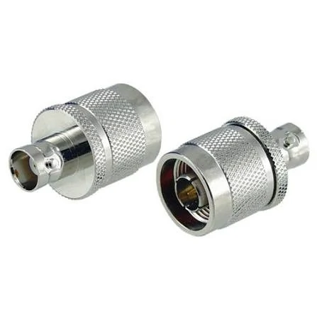
This image shows a coax adapter used for RF interface conversion. Coax adapters help connect different connector standards in RF systems, including laboratory testing equipment, communication devices, and antenna applications.
RF equipment rarely uses the same connector interface everywhere. A test instrument may use a BNC port, a communication module may use SMA, and an outdoor antenna system may use an N Type connector.
A typical RF chain may include:
Equipment Port → Coax Adapter → Cable Assembly → Antenna or RF Module
The adapter solves the physical mismatch between two components, but it does not remove the need for proper RF design.
A correct connection requires more than matching the connector name. Engineers normally need to confirm:
- Connector family
- Male and female interface
- Impedance
- Frequency range
- Cable compatibility
- Application environment
For example, an SMA female-to-N male adapter and an SMA male-to-N female adapter may look similar in a product list, but they serve opposite connection directions. Selecting the wrong gender can stop assembly completely or require additional adapters that increase loss.
Explain why coax adapters are used in RF connection systems
The main purpose of a coax adapter is interface conversion.
Integrating antenna systems
Wireless devices may use compact connectors internally while external antennas use larger interfaces. A coax adapter bridges the mechanical difference between these systems.
Supporting prototype development
During the development stage, the final cable routing may not be fixed. Adapters provide flexibility before the production assembly is finalized.
However, flexibility has a trade-off. Every additional RF interface introduces another transition point. At higher frequencies, small mechanical differences in contact geometry, dielectric structure, and alignment can affect insertion loss and VSWR.
Identify where coax adapters appear in RF signal chains
Coax adapters are used across many RF applications:
| Application Area | Typical Adapter Use | Main Check |
| RF laboratory testing | Connecting different test instruments | Frequency range and VSWR |
| Antenna systems | Matching antenna connector standards | Impedance and environment |
| Wireless modules | Converting compact RF interfaces | Cable compatibility |
| Communication equipment | Field replacement and upgrades | Mechanical stability |
| Prototype systems | Temporary RF connections | Repeatability |
The adapter itself is only one part of the RF path. A system can fail even when the adapter specification appears correct.
For example, a 50Ω coax adapter connected to the wrong cable type may still create an unwanted transition. The connector interface matches, but the complete assembly does not.
This is why experienced buyers usually specify the whole connection requirement rather than ordering by connector name alone.
A request such as:
“Need coax adapter”
does not provide enough information.
A better specification would be:
“SMA female to N male coax adapter, 50Ω, DC–6 GHz, for antenna testing application.”
That description immediately defines the mechanical interfaces, electrical requirement, and intended use.
How Should You Match Coax Adapter Interfaces Before Ordering?
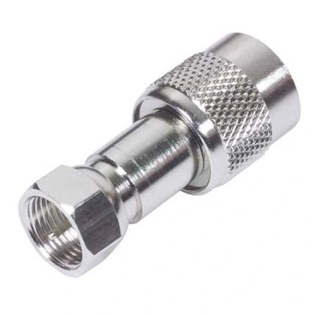
This image presents an SMA coax adapter designed for RF connector conversion. SMA adapters are widely used in wireless communication equipment, RF testing systems, and high-frequency applications.
Many adapter selection problems start before the purchase order is created. The mistake is usually not the product itself; it is incomplete information in the BOM or RF request.
Before selecting a coax adapter, confirm both sides of the connection.
The first side may be:
- SMA
- BNC
- N Type
- TNC
- F Type
The second side may use a different standard depending on the equipment.
A correct adapter must match both interfaces:
Connector A + Connector B + Gender + Impedance + Frequency Range
Confirm both connector families before selecting an adapter
Different connector families have different mechanical structures and application ranges.
| Adapter Conversion | Common Application | Key Check |
| SMA ↔ N | RF modules and antennas | Gender and frequency |
| SMA ↔ BNC | Laboratory equipment | Impedance |
| BNC ↔ TNC | Rugged RF connections | Thread compatibility |
| Coax ↔ SMA | Cable transition | Cable size |
| Coax ↔ N | Outdoor RF systems | Environment rating |
| F Type ↔ Coax | Broadband systems | 75Ω matching |
The connector body is only the starting point. The final selection depends on how the adapter will be used.
A test setup operating at several GHz may require a precision adapter with controlled VSWR characteristics.
For procurement teams, the safest approach is to include the complete RF requirement in the BOM:
- Interface A
- Interface B
- Male/Female direction
- Impedance
- Frequency range
- Application
- Required inspection level
This prevents a common production problem: receiving a mechanically correct part that cannot meet the electrical requirement.
How Does Impedance Affect Coax Adapter Selection?
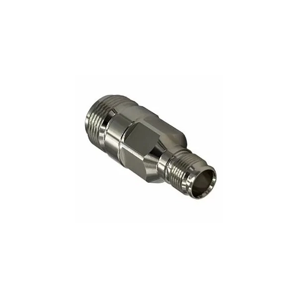
This image illustrates an RF coax adapter used in signal transmission systems. Selecting the correct impedance, connector type, and frequency range helps maintain stable RF performance.
A coax adapter can be mechanically correct and still be electrically wrong.
This situation appears more often than expected in RF sourcing. The connector can be screwed together, the cable can be installed, and a continuity test can pass. The problem only becomes visible when the system is measured at operating frequency.
The reason is simple: RF systems are not only connected by metal parts. They depend on controlled impedance throughout the signal path.
Most RF applications use 50Ω systems. Some broadband and video systems use 75Ω instead. The two standards may look similar from the outside, but they are built for different signal environments.
A coax adapter should follow the impedance of the system, not just the connector shape.
Match 50Ω adapters with RF communication systems
A large number of RF adapter applications are based on 50Ω impedance.
Typical examples include:
- Wireless communication equipment
- Antenna feed systems
- RF testing platforms
- Microwave modules
- GPS and positioning devices
For these applications, common adapter combinations include SMA, N Type, TNC, and BNC transitions.
A buyer requesting an adapter should normally provide more than the connector names.
For example:
“SMA to N adapter”
The difference between two similar-looking adapters can affect whether the final assembly works correctly.
A practical RF specification usually looks like:
| Requirement | Example |
| Connector A | SMA female |
| Connector B | N male |
| Impedance | 50Ω |
| Frequency | DC–6 GHz |
| Application | Antenna testing |
| Environment | Indoor laboratory |
This format gives suppliers enough information to evaluate the correct construction.
Understand where 75Ω coax adapter applications appear
75Ω adapters are mainly associated with broadband signal systems.
Common applications include:
- CATV networks
- Video transmission
- Television distribution
- Broadband communication systems
The selection mistake usually happens when users see the same connector family and assume the parts are interchangeable.
A connector interface only describes the mechanical connection. It does not guarantee that the electrical characteristics are the same.
For example, a BNC interface can appear in both 50Ω and 75Ω applications. The correct choice depends on the equipment specification, not the connector name alone.
Avoid selecting adapters only by mechanical fit
Mechanical matching is the first step, not the final decision.
A complete RF adapter check should include:
- Interface type
- Connector gender
- Impedance
- Frequency range
- Cable compatibility
- Installation environment
A common purchasing problem is caused by incomplete BOM descriptions.
“Need SMA adapter”
is difficult to evaluate.
“SMA female to BNC male 50Ω adapter for RF test equipment, DC–4 GHz”
provides a clear engineering requirement.
The second description reduces communication time and prevents incorrect substitutions.
How Do SMA, BNC, N Type, and TNC Coax Adapters Compare?
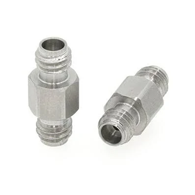
This image shows a coax adapter with different RF connector interfaces. Adapter selection requires checking connector type, gender, impedance, and operating frequency.
Different connector families exist because RF systems have different priorities.
A compact wireless module does not have the same requirements as an outdoor antenna system. A laboratory fixture does not face the same mechanical conditions as a vehicle communication device.
The connector choice should follow the application.
Select SMA adapters for compact RF equipment
SMA adapters are common in compact RF designs.
Typical applications:
- Wireless modules
- GPS equipment
- RF evaluation boards
- Small antenna assemblies
- Test fixtures
Their compact structure makes them suitable where installation space is limited.
However, compact size also means the mechanical details become more sensitive.
For low-frequency applications, the difference may not be obvious. At higher frequencies, the same difference can appear during VNA testing.
Select BNC adapters for laboratory and general test connections
BNC adapters are widely recognized in electronic test environments.
The main advantage is not maximum frequency capability. It is convenience.
The bayonet locking structure allows fast connection and removal, which is useful during:
- Oscilloscope measurements
- Signal generator setup
- Laboratory testing
- Prototype debugging
For RF applications, the actual frequency specification should still be checked.
A BNC adapter used for a basic measurement connection is not automatically suitable for microwave testing.
The test requirement determines the part selection.
How Can You Decide Between a Coax Adapter and a Cable Assembly?

This image shows an SMA male coax adapter suitable for RF test equipment, communication systems, and antenna connection applications where reliable signal transmission is required.
However, the number of transitions should be controlled.
An RF path containing several adapters may introduce:
- Additional insertion loss
- More mechanical interfaces
- More opportunities for mismatch
- More points requiring inspection
A setup that works during prototype testing may become difficult to control in production.
Use cable assemblies when repeatability matters
A dedicated RF cable assembly can reduce unnecessary connections.
Instead of:
Equipment → Adapter → Cable → Adapter → Antenna
a production system may use:
Equipment → Custom Cable Assembly → Antenna
This reduces the number of interfaces and simplifies installation.
The decision can be summarized:
| Situation | More Suitable Choice |
| Temporary laboratory connection | Coax adapter |
| Prototype evaluation | Coax adapter |
| Fixed equipment installation | Cable assembly |
| Repeated production assembly | Cable assembly |
| High-frequency measurement path | Minimize adapter count |
A useful purchasing question is:
“Will this adapter remain in the final product, or is it only helping during development?”
If it becomes part of the permanent RF path, a dedicated cable assembly is often easier to control.
The adapter is not the problem. The problem is using a temporary connection method as a permanent design solution.
How Does Frequency Change the Way You Select a Coax Adapter?
A connector that works at one frequency may become a limitation when the system moves higher.
This problem is common in RF projects. During early testing, engineers often use available adapters from the lab shelf. The prototype works, measurements look acceptable, and the project moves forward.
The problem appears when the design enters a stricter test stage.
The same adapter may introduce unstable readings near the upper operating band. The reason is not always a visible defect. At higher frequencies, small changes in the RF transition area can affect the result.
Inside a coax adapter, the following details influence RF behavior:
- Contact alignment
- Dielectric structure
- Machining tolerance
- Plating condition
- Connector interface quality
A DC-rated adapter and a microwave-rated adapter may look almost identical externally, but their internal design requirements are different.
Check the operating margin instead of matching the number only
Many buyers look at the frequency value first:
“System frequency: 6 GHz”
“Adapter frequency: 6 GHz”
This looks acceptable, but there is little margin.
In practical RF projects, engineers usually prefer some frequency headroom because the real system includes more than one component.
The complete path may contain:
- Cable loss
- Connector transitions
- Additional adapters
- Test fixtures
- Antenna interfaces
A simple reference calculation can help during selection:
Frequency Margin Ratio = Adapter Rated Frequency ÷ Maximum Operating Frequency
| Ratio | Practical Meaning |
| Less than 1.2 | Very little margin, review carefully |
| 1.2–1.5 | Suitable for many general RF connections |
| 1.5–2.0 | Better for measurement and development work |
| Above 2.0 | Preferred for sensitive RF paths |
This is not a replacement for actual testing. It is a quick method for avoiding a common mistake: selecting a component that only works at the edge of its specification.
Why test systems need more attention
A coax adapter used in a production machine and an adapter used in a VNA setup may have different requirements.
For a general communication device, the main concern may be mechanical compatibility.
For RF measurement equipment, engineers may care more about:
- Repeatability
- VSWR stability
- Connector wear
- Calibration influence
A measurement setup can be affected by small changes that are ignored in ordinary connections.
For this reason, test engineers often keep dedicated adapters for calibration and measurement work rather than mixing them with general-purpose parts.
How Should You Inspect and Verify a Coax Adapter After Installation?
The installation process is often overlooked because an adapter appears simple.
However, RF connectors are precision mechanical parts. Damage that does not stop assembly can still affect electrical results.
A connector can tighten normally while having:
- Damaged threads
- Contaminated contact surfaces
- Poor center pin contact
- Excessive mechanical stress
These issues are difficult to identify through appearance alone.
Check the mechanical condition before connection
Before mating an adapter, inspect:
| Inspection Point | Possible Issue |
| Thread section | Difficult tightening or loose connection |
| Center contact | Poor signal contact |
| Plating surface | Wear or oxidation |
| Connector face | Dirt or physical damage |
| Housing | Deformation from impact |
For frequently used laboratory adapters, this inspection becomes more important because repeated mating gradually affects the connector interface.
Continuity testing is useful, but not enough
A continuity test answers one question:
“Is there an electrical connection?”
It does not answer:
“Will the RF signal behave correctly at operating frequency?”
For RF applications, additional verification may include:
| Test Method | Purpose |
| Continuity test | Check basic electrical path |
| VSWR measurement | Evaluate reflection |
| Insertion loss test | Measure signal loss |
| VNA sweep | Check RF behavior |
| Visual inspection | Confirm mechanical condition |
The required test level depends on the project.
A temporary laboratory connection may not need the same inspection level as a production RF assembly.
What Information Should Be Included When Ordering a Coax Adapter?
Many purchasing errors come from incomplete descriptions.
The supplier receives:
“Need SMA adapter.”
The problem is that several different products could match that sentence.
Possible differences include:
- SMA male or female
- Straight or right angle
- Panel mount or cable mount
- 50Ω or another impedance
- Low-frequency or microwave version
A clearer request saves time for both sides.
Write the RF requirement, not only the product name
A useful purchasing description should include:
| Item | Example |
| Connector side A | SMA female |
| Connector side B | N male |
| Impedance | 50Ω |
| Frequency | DC–6 GHz |
| Application | Antenna testing |
| Quantity | Prototype / production |
| Drawing | Required for replacement |
For replacement projects, photos are often valuable.
Two adapters may have the same connector names but different:
- Overall length
- Mounting dimensions
- Thread position
- Internal structure
A photo or drawing can prevent incorrect substitution.
Include application details when the adapter is part of a system
The same adapter may be used differently in different environments.
A laboratory adapter may prioritize measurement accuracy.
An outdoor antenna adapter may need:
- Weather resistance
- Mechanical strength
- Stable mounting
A production buyer should provide the actual working condition instead of assuming the connector specification tells the whole story.
Coax Adapter Pre-Purchase Verification Sheet
Before placing an order, the following checklist can reduce avoidable mistakes:
| Check Item | Confirm Before Order |
| Interface A | Connector type and gender |
| Interface B | Connector type and gender |
| Impedance | 50Ω / 75Ω confirmed |
| Frequency | Above operating requirement |
| Application | Test, antenna, communication, production |
| Installation | Indoor, outdoor, panel, cable |
| Quantity | Sample or production volume |
| Inspection | Appearance / RF test requirement |
This information is usually enough for suppliers and engineers to discuss the correct solution.
FAQ
Can a coax adapter solve an impedance mismatch?
No.
An adapter changes the physical connection between two interfaces. It does not automatically correct an impedance mismatch in the RF system.
Can SMA and N Type adapters replace each other?
No.
They use different mechanical structures and are normally used in different application environments.
The correct transition requires matching the connector type, gender, impedance, and frequency range.
How many coax adapters can be used in one RF path?
There is no universal limit.
The practical approach is to minimize unnecessary transitions, especially in higher-frequency systems.
Every additional connection introduces another mechanical and electrical interface.
Should I use a coax adapter or a custom cable assembly?
Use an adapter when flexibility is needed.
Use a cable assembly when the connection becomes part of the final product.
For repeated production use, a fixed cable assembly is often easier to control.
What should engineers provide for a custom coax adapter request?
A complete request normally includes:
- Connector interfaces
- Gender
- Impedance
- Frequency requirement
- Application
- Quantity
- Drawing or reference sample
The clearer the information, the lower the chance of receiving a mechanically suitable but electrically unsuitable part.
