
An SMA bulkhead connector can fit through the enclosure wall, accept the mating cable, and still be wrong for the finished equipment.
The problem often appears after the first prototype. The connector drawing looked correct. The panel hole matched. The mounting nut could be tightened. Then the enclosure was closed and the internal coax twisted with the connector body, the gasket consumed more thread than expected, or repeated external mating slowly rotated the bulkhead inside the panel.
None of those failures are solved by checking only the SMA interface.
For enclosure integration, the useful question is not simply whether the connector fits the hole. The mechanical load path, finished panel stack, remaining thread engagement, anti-rotation method, chassis contact, and internal cable route all need to work together.
How Should the Bulkhead Carry Load Through the Enclosure?
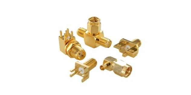
Collection of SMA bulkhead connectors showing PCB mount, right-angle, threaded bulkhead, and adapter configurations for RF enclosure and equipment integration.
A bulkhead installation should transfer mounting force through the connector shoulder, finished panel, washer arrangement, and mounting nut. The internal coax should not become part of that load path.
That sounds obvious until assembly starts.
If an operator holds the rear cable while tightening the panel nut, or if the connector body has no practical anti-rotation feature, tightening torque can be transferred directly into the coax termination. A cable that was originally straight may leave the rear body already twisted before the equipment has even passed final inspection.
Define the Shoulder, Panel, Washer, and Nut Load Path
Start with the mechanical stack.
The connector shoulder should seat against the intended panel surface. Washers and locking hardware should then clamp the connector without forcing the cable or rear termination to carry the tightening load.
The exact hardware varies by connector design. Some assemblies use a flat washer and nut. Others add a lock washer, gasket, O-ring, keyed feature, or custom anti-rotation geometry.
The engineering drawing should show which surfaces actually locate the connector.
A common sourcing mistake is approving the front-interface dimensions while leaving the panel-side hardware loosely defined in the BOM. Two suppliers may then provide parts that both mate with SMA, but use different shoulder dimensions, thread lengths, washer stacks, or rear-body geometry.
That difference may not appear until production assembly.
Prevent Connector-Body Rotation During Nut Tightening
The mounting nut turns. The connector body should not.
If the complete body rotates while the nut is tightened, the rear cable can rotate with it. Thin coax such as RG174 or RG178 is particularly easy to disturb because a small body rotation becomes noticeable torsion over a short internal cable length.
The risk becomes higher when the cable is already terminated to a PCB, RF module, or second connector.
Anti-rotation control may come from connector geometry, a shaped panel cutout, a locating shoulder, a fixture, or the assembly process itself. The correct method depends on the specific part.
What matters is that it is defined before volume production.
A useful first-article inspection is simple: mark the connector body relative to the panel, tighten the mounting hardware using the approved method, and verify that the reference mark does not move.
Keep the Internal Cable Outside the Clamp Load Path
The rear coax needs its own routing and strain-control logic.
Do not use cable tension to hold the connector in position while the nut is tightened. Do not force a short cable assembly between a bulkhead and RF module so tightly that the cable continuously pulls on both terminations.
A finished cable can pass continuity testing and still be mechanically poor.
After assembly, inspect the cable immediately behind the bulkhead. Look for torsion, a sharp bend, braid deformation, or a cable route that changes when the panel hardware is tightened.
For internal routing details, the SMA Bulkhead Cable Design Guide can be used alongside this enclosure-integration check. The two tasks are related, but they are not the same: cable routing manages the internal path, while bulkhead integration controls how panel loads enter the assembly.
Separate Mating Torque From Bulkhead Mounting Torque
The SMA mating nut and the bulkhead mounting nut perform different jobs.
The mating interface establishes the RF connection between two SMA interfaces. The bulkhead nut fixes the connector to the enclosure. Treating both as the same tightening operation can create an assembly process that is difficult to control.
Use the connector drawing, assembly specification, or supplier-controlled instruction for the required mounting method. Do not invent one universal torque value for every SMA bulkhead design.
That becomes especially important when the panel uses soft material, a gasket, thin sheet metal, or a finish that can compress under the mounting hardware.
Which Finished Panel Stack-Up Must Be Verified?
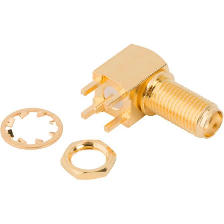
Right-angle SMA PCB bulkhead connector with threaded mounting section, nut, and washer for compact RF enclosure and circuit board integration.
Bare sheet thickness is not enough.
If the mechanical drawing says the enclosure wall is 2.0 mm thick, the connector may still see a larger installed stack after powder coating, gasket material, washers, and other hardware are added.
The dimension that matters is the finished stack through which the threaded bulkhead must actually pass.
Measure Finished Panel Thickness Instead of Bare Sheet Thickness
Record the panel in its production condition.
Check paint, powder coating, anodizing, gasket thickness, flat washers, lock washers, and any local reinforcement plate that shares the threaded section.
Even small additions matter when the original design already uses most of the available thread.
A prototype assembled on an unfinished aluminum panel may therefore pass, while the production enclosure with coating and gasket leaves insufficient engagement for the nut.
Calculate the Usable Thread After the Complete Stack-Up
Do not approve a connector simply because its nominal thread length exceeds the nominal sheet thickness.
Instead, compare the minimum usable connector thread against the maximum expected installed stack.
The remaining thread must still satisfy the engagement requirement defined for that specific connector and mounting hardware.
That means engineering should work from tolerances, not only nominal dimensions.
If panel thickness, gasket compression, washer thickness, or connector thread tolerance is still unknown, the design is not ready to freeze. Label the stack as unverified rather than assuming production parts will fit.
Rear-side access deserves the same attention. A connector may have enough thread but still be impossible to tighten because a PCB, shield can, fan, bracket, or enclosure rib blocks the wrench path.
For the first article, assemble the real connector into the real finished enclosure using the intended tool. That single check often exposes problems that the connector drawing alone cannot show.
How Should the Internal Coax Leave the Bulkhead?
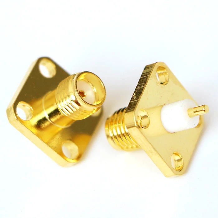
Gold-plated SMA 4-hole flange bulkhead connector designed for secure panel mounting, RF chassis integration, antenna systems, and test equipment.
The rear side of an SMA bulkhead connector is often where an enclosure design becomes difficult.
A connector may fit the panel perfectly, yet the cable exits directly toward a PCB edge, battery pack, shield can, fan, or enclosure cover. At that point, the problem is no longer the SMA interface. It is the geometry behind the panel.
Define the cable exit direction before freezing the connector and cable assembly.
An axial cable exit works well when enough depth is available behind the panel. A right-angle exit may reduce enclosure depth, but it creates a fixed routing direction and can make assembly orientation more sensitive. In a tightly packed product, even deciding whether the cable leaves upward or downward can affect whether the assembly can be installed without forcing the coax.
Protect the Cable Bend Near the Rear Body
The first bend deserves attention.
RG174, RG178, RG316, and other small coaxial cables are flexible, but that does not mean they should be folded immediately behind the connector body. A sharp bend close to the termination can place additional stress on the braid, dielectric, center conductor, or ferrule area.
The allowable bend radius depends on the exact cable construction. Use the cable manufacturer’s data where it is available.
For first-article assembly, inspect the cable in its final installed position rather than on an open bench. The cover, PCB, and other components can push the coax into a tighter path than expected.
A cable can test normally before installation and change once the enclosure closes.
Add a Service Loop Without Adding Unnecessary Cable
A short service loop can make assembly and maintenance easier.
It gives technicians some freedom to connect a module before final placement, absorbs small positional tolerances, and reduces direct tension between the bulkhead and internal RF connector.
Too much extra cable creates another problem.
Longer coax adds attenuation, consumes enclosure space, and may be pushed into uncontrolled bends when the cover closes. The goal is not to maximize slack. It is to provide enough controlled length for assembly without turning the cable into a loose coil.
For more detailed cable-family comparisons, the RG Cable Guide can be used when deciding between RG174, RG178, RG316, and other internal coax options.
How Do You Match the Rear Cable End to the Internal RF Module?
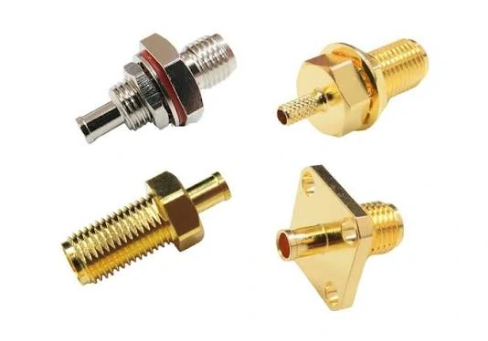
Different SMA bulkhead connector mounting configurations including threaded bulkhead, panel mount, and flange styles for RF equipment integration.
The bulkhead side usually gets most of the attention because it is visible from outside the equipment.
The module-side termination can be more restrictive.
PCB position, connector orientation, available height, cable bend direction, and service access often determine whether the rear end should use a straight connector, right-angle connector, direct solder termination, or another RF interface.
Do not select the coax only from the SMA bulkhead connector.
Select it from the complete path.
| Internal Constraint | Likely Design Concern | Practical Check |
| Very limited enclosure depth | Axial cable exit may interfere | Check rear-body plus bend envelope |
| PCB connector close to panel | Excess cable may create a tight loop | Prototype actual assembly length |
| Module connector faces sideways | Straight cable end may twist coax | Compare right-angle termination |
| Frequent module servicing | Short cable may prevent access | Add controlled service length |
| High-frequency RF path | Cable and termination may dominate loss | Test complete assembly with VNA |
This comparison is more useful than simply labeling one cable “better” than another. The correct choice depends on the geometry and RF requirement of the assembly.
Confirm Cable-Side Termination Dimensions
For crimped or soldered cable connectors, cable compatibility must be more specific than a generic cable family name.
Confirm:
- cable outer diameter;
- dielectric diameter;
- center conductor size;
- braid construction;
- ferrule size;
- strip dimensions;
- required crimp die or solder process.
An SMA cable connector intended for one coax size should not automatically be substituted for another because the front mating interface looks identical.
RG174 and RG316, for example, may appear similar in a sourcing list, but the exact termination geometry still needs verification against the selected connector.
Avoid Rigid Adapter Stacks When a Flexible Assembly Solves the Alignment Problem
If the bulkhead connector and module port do not align on the same axis, stacking several rigid adapters can look convenient during prototyping.
It can also create mechanical leverage, additional mating interfaces, extra mismatch, and more potential failure points.
A short flexible coax assembly often handles positional tolerance more naturally.
That does not mean flexible cable is always electrically superior. Every connector pair and cable length adds its own RF penalty. The point is mechanical: flexible cable is often a better way to absorb enclosure alignment error than forcing multiple rigid RF interfaces to carry it.
How Can the Panel Interface Preserve RF Grounding?
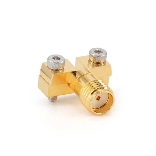
Gold-plated SMA bulkhead connector with dual screw clamp structure, designed for RF enclosure, chassis, fixture, and panel-mounted applications.
Mechanical mounting and electrical bonding are related, but they are not automatically the same thing.
If the SMA bulkhead body is intended to bond to the chassis, the actual conductive path should be identified in the enclosure design.
A metal connector body touching a metal panel may provide a conductive path. Paint, powder coating, anodizing, insulating washers, or sealing materials can change that assumption.
The assembled condition is what matters.
Separate Environmental Sealing From Electrical Bonding
A gasket or O-ring may be necessary for moisture or dust control, but sealing hardware can alter where the connector makes conductive contact with the enclosure.
Do not assume that improving sealing automatically preserves the intended chassis bond.
If electrical grounding is required, document which surface or hardware provides it. This may be the connector shoulder, washer, mounting nut, dedicated grounding feature, or another controlled contact area depending on the design.
Then verify continuity after final assembly.
Testing the loose connector tells you very little about whether the installed chassis path is correct.
When Is a Finished Bulkhead Cable Assembly Better Than a Loose Connector?
Buying a loose SMA bulkhead connector gives the production line more flexibility.
It also transfers more process control to the assembler.
A finished bulkhead cable assembly can reduce that variability when the enclosure geometry is already defined. Cable type, length, rear termination, strip dimensions, ferrule, center pin, and assembly process can all be frozen before the part reaches final equipment assembly.
That is useful when production consistency matters more than last-minute flexibility.
Loose connectors still make sense when the factory already controls cable cutting, stripping, crimping or soldering, inspection, and RF testing.
In that case, the BOM should specify more than the words “SMA bulkhead for RG316.”
At minimum, freeze the connector part number, cable part number, strip dimensions, tooling, termination method, and inspection requirement.
The connector itself may cost less as a loose component. The complete installed cost can move in the opposite direction once labor, rework, scrap, training, and RF inspection are included.
For a new enclosure, approving one actual first-article assembly is therefore far more useful than approving a connector drawing alone.
Which Failures Only Appear After the Enclosure Is Closed?
An SMA bulkhead assembly can pass bench testing and still fail after final installation.
The enclosure changes the mechanical condition of the RF path. A cover can push the coax downward. A bracket can reduce bend radius. A service loop can become trapped between two parts. Repeated mating from outside the equipment can slowly transfer torque into a poorly restrained bulkhead body.
These are integration failures, not necessarily connector failures.
Diagnose Intermittent RF After Cable Compression
If the RF path becomes intermittent only after the cover is installed, inspect the cable before replacing the connector.
Look for:
- cable compression against the cover;
- sharp bends near the rear termination;
- movement of the center conductor or ferrule;
- trapped service loops;
- tension between the bulkhead and internal module.
A useful troubleshooting test is to compare the RF measurement with the enclosure open and closed.
If S11, VSWR, or insertion loss changes after the cable is placed in its final route, investigate the installed cable geometry before assuming the SMA interface is defective.
Investigate Bulkhead Rotation After Repeated Mating
The bulkhead may also move gradually rather than fail during initial assembly.
Every time an antenna or external test cable is connected, mating torque is applied at the front of the connector. If the panel mount lacks enough anti-rotation control, repeated mating can slowly rotate the body.
That rotation may eventually twist the internal coax.
A connector that repeatedly comes loose should therefore be inspected as a complete mounting system: connector shoulder, panel cutout, mounting nut, washer arrangement, anti-rotation feature, and internal cable strain relief.
How Can You Qualify the Complete Panel Interface?
A connector drawing is not a qualification test.
Production approval should be based on the complete installed interface: connector, finished panel, gasket, washer, mounting hardware, internal cable, RF module, and actual enclosure geometry.
The following matrix can be used as a first-article review tool.
| Qualification Field | Engineering Input | Approval Rule |
| Connector PN | Exact approved model | Must match drawing |
| Finished panel thickness | Min / nominal / max | Must fit usable thread |
| Gasket thickness | Compressed value | Included in stack |
| Washer arrangement | Actual production hardware | Must match BOM |
| Anti-rotation method | Panel or fixture design | Verified during tightening |
| Cable exit direction | Installed route | No interference |
| Cable bend | Final enclosure condition | Within cable requirement |
| Chassis grounding | Bonded or isolated | Verified as designed |
| Internal clearance | PCB, cover, bracket | No contact or compression |
| RF test | Project frequency range | Meets project limit |
| First article | Actual enclosure | Approved before release |
This is not a substitute for the connector manufacturer’s drawing or the equipment qualification plan. It is a way to prevent missing mechanical and sourcing inputs before production.
How Should Buyers Freeze the SMA Bulkhead Configuration for Production?
Once the first article is approved, freeze the configuration that actually passed.
The controlled drawing or BOM should identify the connector part number, cable part number, overall assembly length, panel reference, gender, impedance, rear termination, and relevant hardware.
That leaves too much room for substitution.
A more useful production note would state the exact connector and cable part numbers, finished length, panel orientation, mounting hardware, termination method, inspection requirement, and drawing revision.
Trigger Reapproval When Critical Items Change
Reapproval should be considered when a change affects the mechanical or RF condition that was originally qualified.
Typical triggers include:
- connector part number changes;
- cable supplier or cable part number changes;
- panel finish changes;
- gasket changes;
- thread length changes;
- rear termination changes;
- cable routing changes;
- overall cable length changes.
Not every change requires a full qualification program, but each critical change should be reviewed against the original first-article conditions.
FAQ
Can a bulkhead connector fit the panel but still be mechanically wrong?
Yes. The connector may pass through the cutout while still having insufficient nut engagement, poor anti-rotation control, inadequate rear clearance, or the wrong washer and gasket stack.
Why does an SMA bulkhead connector rotate when I connect an external cable?
The panel mount may be loose, the connector may lack an effective anti-rotation feature, or external mating torque may be transferring into the connector body. Inspect the mounting structure rather than only retightening the cable.
Should paint, gaskets, and washers count toward panel thickness?
Yes. Thread calculations should use the complete finished stack, not only the original sheet-metal thickness.
Can RG174 and RG316 use the same rear termination?
Not automatically. Cable OD, dielectric size, center conductor, braid, ferrule, strip dimensions, and tooling need to match the exact cable.
Why can an assembly pass RF testing before installation but fail afterward?
The installed route may introduce tighter bends, compression, connector rotation, or strain at a termination. RF testing near the target operating band is more meaningful when the cable is in its final mechanical condition.