
A connector can pass a basic continuity test and still create problems after it enters a finished enclosure.
This happens often with panel-mounted RF ports. The connector fits the hole, the SMA interface mates correctly, and the first bench test looks normal. The issue appears later when the cable is bent inside the equipment, the panel thickness changes, or the RF path is extended with additional adapters.
A sma bulkhead connector is not selected only by its SMA interface. The mounting method, cable connection style, impedance, frequency range, and mechanical structure all affect the final RF path.
For equipment manufacturers, the bulkhead structure solves a practical problem: how to create a fixed RF access point on a metal enclosure, test panel, or communication device without allowing the cable assembly to move freely.
How Do SMA Bulkhead Connectors Create Fixed RF Interfaces?
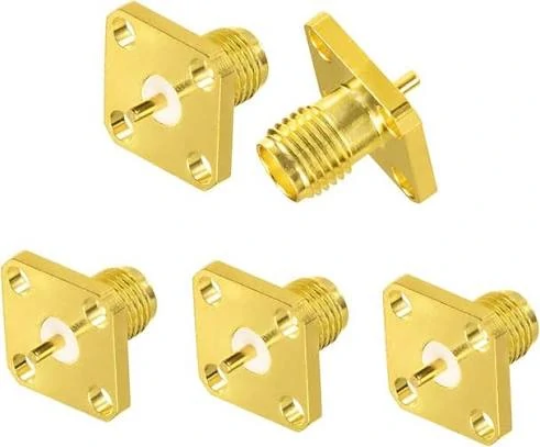
This SMA flange panel mount connector uses a multi-hole fixing structure to provide stronger mechanical support. It is commonly used in RF test equipment, communication systems, and precision electronic devices.
For RF equipment designers, the mechanical interface is often just as important as the electrical interface. A connector that works electrically but cannot maintain stable mounting pressure may create problems during vibration, repeated mating, or environmental testing.
Typical applications include:
The important point is that a bulkhead connector becomes part of the equipment structure. The panel thickness, mounting hole size, and fixing method must be considered before ordering.
Identify Where Panel-Mounted SMA Connections Are Required
Many purchasing mistakes happen because the connector name is specified without the installation environment.
A request such as “need SMA connector” does not provide enough information for production.
Examples include:
- RF measurement instruments
- Wireless communication cabinets
- GPS and antenna modules
- Industrial monitoring equipment
- Outdoor communication terminals
A common sourcing mistake is selecting a connector only from a product image. Two SMA connectors may look similar externally, but the rear structure can be completely different. One may be designed for RG316 cable, while another may require a larger coax cable. The front SMA interface alone does not determine compatibility.
How Does Bulkhead SMA Compare With Other SMA Mounting Styles?
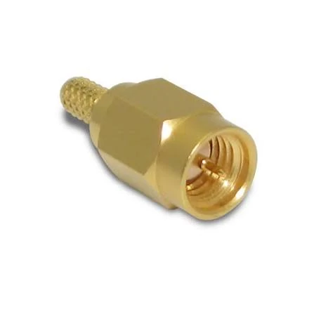
This SMA bulkhead connector provides a stable RF interface for equipment panels, communication devices, antenna systems, and test fixtures. The panel mount structure helps create a fixed external RF access point while maintaining reliable SMA connections.
SMA connectors are available in different mechanical configurations. The correct choice depends on where the connector sits in the RF system.
A bulkhead SMA is mainly a mechanical integration solution. It does not automatically provide better RF performance than every cable-mounted SMA connector.
The RF result still depends on the complete assembly:
- Connector design
- Cable type
- Cable length
- Termination quality
- Frequency range
- Number of adapters in the signal path
For example, a correctly mounted SMA bulkhead connector with a suitable low-loss cable can perform well in a microwave test setup. However, a poor cable match or damaged termination may increase VSWR even when the bulkhead mounting itself is correct.
Practical Selection Rule: Check Mechanical Fit Before RF Testing
Before testing RF performance, confirm that the connector physically fits the equipment.
A simple mechanical review should include:
A connector that is mechanically unstable may pass initial testing but fail after assembly changes.
For OEM projects, the RF drawing should include more than the connector name. A complete specification normally includes interface type, gender, mounting method, impedance, operating frequency, cable requirement, and drawing information.
The next step is matching the SMA bulkhead connector with the correct RF cable and confirming whether the complete RF path can meet the required VSWR, insertion loss, and frequency target.
How Do You Select the Correct Panel Mount SMA Connector?
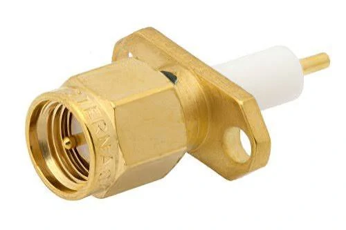
This flange SMA bulkhead connector features a screw mounting structure for improved mechanical stability. It is suitable for RF test fixtures, communication equipment, and applications requiring a fixed panel connection.
A panel-mounted RF connector usually fails at the mechanical stage before it fails electrically.
During prototype development, engineers often focus on the SMA interface, frequency range, and cable type. The mounting details are sometimes checked later, especially when the connector is installed into an existing enclosure.
That is where problems appear.
A bulkhead SMA connector that works on a test bench may not fit the production housing because the mounting hole, panel thickness, or internal clearance is different from the original sample.
For a panel mount SMA connector, the mechanical drawing is part of the RF specification.
Before ordering, engineers normally need to confirm:
- Panel thickness
- Mounting hole diameter
- Thread length
- Flange dimensions
- Cable exit direction
- Available space behind the panel
A few millimeters can decide whether the connector can be assembled smoothly.
For example, a threaded SMA bulkhead installed on a thin aluminum panel may require a different body length compared with the same connector mounted on a thicker equipment chassis. If the threaded section is too long, the connector may interfere with internal brackets. If it is too short, the fixing nut cannot provide enough mechanical support.
What Information Should Engineers Provide Before Selecting a Panel Mount SMA Connector?
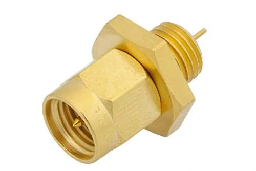
The SMA female bulkhead connector is designed for panel mounting applications where compact size and reliable RF transmission are required. It provides a fixed SMA interface for antennas, wireless modules, and RF equipment.
A product request such as “SMA bulkhead connector, 100 pcs” is usually not enough for accurate matching.
For standard applications, a supplier will normally need information similar to an RF drawing request:
| Required Information | Why It Is Needed |
| Connector gender | Confirm mating interface |
| Mounting style | Select nut or flange structure |
| Panel thickness | Match body length |
| Hole size | Confirm installation fit |
| Cable type | Match rear termination |
| Frequency range | Check RF capability |
| Quantity | Determine production method |
This information becomes more important when replacing an existing connector.
A photograph can help identify the general structure, but it cannot confirm critical dimensions. Two SMA connectors may look identical from the front while using different cable attachment methods or different mounting threads.
For OEM projects, a drawing or sample connector is often the fastest way to avoid repeated sample adjustments.
When Should You Choose Bulkhead, Flange, or Threaded SMA Mounting?
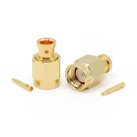
This image shows the internal components of an SMA connector, including the contact pin and connector body. Proper assembly precision affects RF performance, VSWR, and signal transmission stability.
The mounting method depends on how the connector will be used after the equipment leaves the factory.
A laboratory instrument that is connected and disconnected hundreds of times has different requirements from a sealed communication enclosure that is installed once and left outdoors.
Common SMA bulkhead mounting structures include:
| Mounting Style | Main Feature | Suitable Application |
| Threaded bulkhead | Simple installation, limited space requirement | General RF equipment |
| Two-hole flange | Fixed with screws | Equipment panels and modules |
| Four-hole flange | Higher mechanical stability | Test fixtures and precision systems |
| Through-panel structure | Provides external RF access | Enclosures and communication equipment |
A threaded bulkhead design is widely used because installation is simple. The connector passes through the panel and is secured with a nut.
Flange-mounted versions are selected when the connector needs stronger mechanical support.
How Do SMA Male and Female Interfaces Affect Bulkhead Connector Selection?
SMA gender mistakes are among the easiest errors to make during sourcing.
The external thread dimensions can appear correct, but the internal contact structure determines whether two parts actually mate electrically.
A standard SMA interface uses:
- SMA male: center pin contact
- SMA female: socket contact
In many equipment designs, the panel side uses an SMA female bulkhead connector because it becomes a fixed RF port. The external cable assembly then connects using an SMA male plug.
A typical connection may look like:
Equipment panel → SMA female bulkhead → SMA male cable assembly → RF module
Before confirming the order, check the complete connection chain rather than looking at one component.
| Item | Check Point |
| Equipment port | SMA male or female |
| Cable assembly end | Matching opposite gender |
| Adapter requirement | Standard SMA or special transition |
| Frequency range | Suitable for operating band |
The same rule applies when replacing connectors in existing equipment. A physically similar connector may not be electrically compatible.
Why Can RP-SMA Create Confusion During Replacement?
The external thread size is similar to standard SMA, which creates confusion during replacement.
The difference is the center contact arrangement.
| Connector Type | Center Contact |
| Standard SMA male | Pin |
| Standard SMA female | Socket |
| RP-SMA male | Socket |
| RP-SMA female | Pin |
A replacement part may screw onto the original connector but fail because the center contact does not match.
This situation appears often in Wi-Fi equipment repair and antenna upgrades. The mechanical connection looks correct, but the RF path is open or unstable.
For that reason, connector identification should include polarity confirmation, not only the thread specification.
How Do SMA Bulkhead Connectors Match RF Cable Assemblies?
The connector is only one part of the RF path.
A common procurement mistake is selecting the bulkhead connector first and treating the cable as a secondary item. In practice, the rear cable interface determines whether the assembly can be produced correctly.
Different coaxial cables require different connector bodies.
Does the RF Cable Need to Match the SMA Bulkhead Impedance?
The final RF result is also affected by:
- Cable length
- Connector quantity
- Termination quality
- Bend radius
- Operating frequency
A short RG316 cable may work well in a compact control box. The same cable length may not be suitable for a higher-frequency measurement path where insertion loss becomes more important.
For this reason, RF cable selection should be based on the actual system requirement rather than simply choosing the smallest or cheapest cable.
How Do Frequency and RF Performance Affect Bulkhead SMA Selection?
A connector installed in a panel does not work alone.
During RF testing, engineers are usually checking the complete path:
the connector, the cable, the adapters, and the equipment interface.
This is why two SMA bulkhead assemblies with the same connector name can show different test results.
One assembly may pass on a short prototype cable. After the cable length changes or the routing is adjusted inside the enclosure, the VSWR result may move.
The difference is usually related to the complete assembly rather than the SMA interface itself.
When reviewing a bulkhead SMA connector project, engineers normally check:
- Working frequency
- Cable type and length
- Number of RF transitions
- VSWR requirement
- Insertion loss limit
- Test method
A connector suitable for a communication box does not always fit a microwave test fixture.
The application decides the required accuracy level.
Why Should Engineers Leave Frequency Margin for SMA Connectors?
The maximum frequency value on a connector specification sheet should not be treated as the only selection point.
In production, the working environment is different from a laboratory sample.
A connector operating close to its limit may become more sensitive to:
- Cable bending
- Assembly tolerance
- Connector wear
- Additional adapters
- Manufacturing variation
For example, a project using a 6 GHz SMA assembly may have different requirements from a test cable working near 18 GHz.
The connector may look identical from the outside, but the internal structure and manufacturing accuracy become more important at higher frequencies.
A simple selection review can include:
| Item | Check Point |
| System frequency | Actual operating band |
| Connector frequency rating | Confirm sufficient range |
| Cable capability | Avoid cable becoming the limitation |
| Adapter quantity | Reduce unnecessary transitions |
| Test requirement | Match inspection level |
The cable is often overlooked.
A high-frequency SMA bulkhead connector connected with a cable that has high attenuation may not achieve the expected result.
The RF path is only as strong as its weakest part.
How Should Engineers Evaluate RF Loss in a Bulkhead SMA Assembly?
When a customer reports signal loss, the connector is not always the cause.
A complete SMA cable assembly may include several possible loss sources:
- Connector interface
- Cable attenuation
- Adapter transition
- Termination area
This calculation helps during the design stage.
For example, a short RG316 cable inside an electronic enclosure may be acceptable.
The same cable used for a longer microwave connection may create noticeable attenuation.
The cable length, operating frequency, and connector quantity should be reviewed together.
A common mistake in purchasing is selecting a connector first and then finding a cable afterward.
For production, the better approach is to define the complete assembly:
- SMA bulkhead structure
- Cable type
- Cable length
- Termination method
- Required test items
How Are SMA Bulkhead Connectors Used in Antenna and Test Equipment?
Bulkhead mounting is popular because it creates a fixed RF access point.
Instead of opening the enclosure to connect an antenna or test cable, users can connect directly from outside.
Typical applications include:
- Wireless equipment
- GPS devices
- IoT terminals
- RF monitoring systems
- Test fixtures
The connector becomes part of the equipment structure.
That means mechanical conditions matter.
A connector mounted on a laboratory panel and one installed on outdoor equipment may use the same SMA interface but require different designs.
How Do Bulkhead SMA Connectors Work in Antenna Applications?
In antenna equipment, the bulkhead connector normally acts as the transition point between internal electronics and external RF cable.
This may not appear during the first test but can become a field issue after months of operation.
Why Are Bulkhead SMA Connectors Used in RF Test Fixtures?
Test fixtures depend on repeatable connections.
Typical concerns include:
| Condition | Possible Effect |
| Loose mounting | Unstable measurement |
| Damaged thread | Poor mating condition |
| Contact wear | Increased variation |
| Incorrect cable routing | RF change |
For test environments, the connector should maintain the same position after repeated use.
This is one reason flange-mounted SMA bulkhead connectors are sometimes selected for fixtures requiring stronger mechanical support.
How Should SMA Bulkhead Connectors Be Installed and Tested?
Installation should be checked before RF measurement.
A practical inspection sequence is:
- Confirm panel dimensions
- Install the connector
- Check fixing condition
- Route the cable correctly
- Perform electrical testing
Mechanical problems can create symptoms that look like RF problems.
For example:
A loose connector may show unstable VSWR results.
A damaged cable may appear as a connector failure.
The assembly should be checked step by step.
Which Tests Are Used for SMA Bulkhead Assemblies?
Different applications require different inspection levels.
| Test | Purpose |
| Continuity | Confirm electrical connection |
| Insulation test | Check isolation |
| VSWR | Evaluate impedance matching |
| Return loss | Check reflected signal |
| Insertion loss | Measure transmission loss |
Continuity is only the first check.
A cable can have correct electrical connection but still fail RF testing.
Possible reasons include:
- Poor termination
- Incorrect cable selection
- Damaged dielectric
- Impedance variation
For higher-frequency applications, RF measurement becomes necessary.
What Should Buyers Include in an SMA Bulkhead Connector RFQ?
Many RF sourcing problems start with incomplete product descriptions.
A request such as:
“SMA bulkhead connector required”
does not define the actual product.
A more useful RF request includes:
| Specification | Example |
| Interface | SMA bulkhead |
| Gender | Female |
| Mounting | Nut fixing |
| Impedance | 50Ω |
| Frequency | DC-6 GHz |
| Cable | RG316 |
| Length | 500 mm |
| Application | Antenna equipment |
| Test requirement | VSWR check |
For custom projects, additional information helps:
- Mechanical drawing
- Panel thickness
- Installation hole size
- Existing sample
- Environmental condition
Providing these details at the beginning usually reduces repeated sample modification.
FAQ
Can an SMA bulkhead connector be installed on an antenna enclosure?
Yes. This is a common application. The connector provides an external RF port while keeping the internal cable connection fixed. The cable type, impedance, and environmental condition should also be considered.
Is a higher frequency SMA connector always the better choice?
No. The connector should match the actual operating requirement. A higher rating does not automatically improve the complete RF path.
What information should be provided for a custom SMA bulkhead connector?
Provide interface type, gender, mounting method, panel dimensions, cable requirement, frequency range, quantity, and application information.
Why can an SMA bulkhead connector pass initial testing but fail after installation?
A prototype assembly may work correctly during bench testing because the cable is short, straight, and installed in an open environment. After installation into the final enclosure, changes in cable routing, panel mounting condition, connector quantity, or adapter usage can affect the RF result. This is why the complete assembly should be checked after mechanical installation, not only the connector itself.
