
A cable assembly can pass continuity and still produce unreliable RF measurements.
This happens more often than many buyers expect. The connector mates correctly, the cable length matches the drawing, and the first sample performs normally on a test bench. After the assembly enters repeated calibration cycles or production testing, small variations begin to appear: higher VSWR, unstable insertion loss readings, or inconsistent results between operators.
The issue is not always the instrument. The connection path itself can introduce measurement uncertainty.
An RF test connector is not simply a mechanical interface between equipment and a device under test. In measurement systems, it becomes part of the RF path. Connector geometry, impedance matching, mating repeatability, and frequency capability can directly affect test confidence.
For engineers working with VNAs, signal generators, RF fixtures, and microwave measurement systems, connector selection should be considered together with cable type, adapter count, and calibration method.
Why Are RF Test Connectors Important in Measurement Systems?
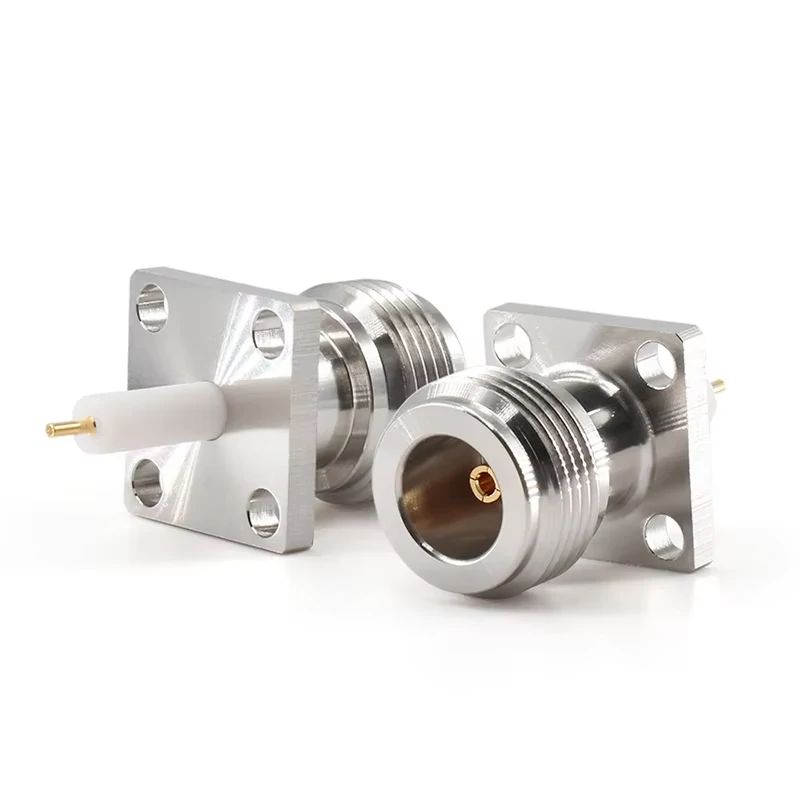
This N Type flange mount RF test connector provides a stable fixed interface for RF measurement paths, test fixtures, communication equipment, and laboratory connection systems. Its panel mount structure helps improve connector alignment and repeatable signal transmission.
A production RF connector and a test connector may look similar from the outside, but their working conditions are different.
Test systems have another priority: repeatable measurements.
During RF testing, the connector must maintain a consistent electrical interface every time it is connected. A small mechanical difference at the mating surface can change the impedance transition and influence measurement results.
Understand how test connectors affect RF measurement accuracy
An RF test connector affects several parts of the measurement process:
- Signal transmission path
- Measurement repeatability
- Calibration accuracy
- Connection stability
Every interface in this path contributes some amount of loss and reflection.
For example, a network analyzer calibration may remove known system errors, but it cannot compensate for a connector that changes behavior because of poor mechanical contact, worn threads, or inconsistent mating.
This is why laboratory environments often require connectors with controlled mechanical dimensions and stable electrical performance.
Identify why standard RF connectors may not meet testing requirements
A common mistake during sourcing is selecting a connector only by interface type.
A buyer may request:
- SMA connector
- 50 ohm connector
- Cable connector
However, a test application usually requires additional details:
| Requirement | Why It Matters |
| Interface type | Ensures equipment compatibility |
| Impedance | Prevents mismatch and reflection |
| Frequency range | Maintains accuracy at target band |
| Mating life | Supports repeated testing |
| Mounting method | Keeps the fixture stable |
For example, an SMA connector used inside a test fixture may need a different mounting structure from an SMA cable connector used in a field antenna system.
A panel mount or bulkhead structure can provide a fixed reference point, while a flexible cable connector may introduce movement during repeated operation.
The connector is not selected only because it fits. It is selected because the entire measurement process depends on it.
How Do You Build a Reliable RF Measurement Path?
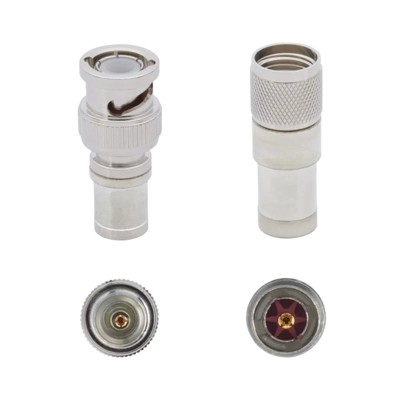
A stable RF measurement path starts before the connector reaches the laboratory.
The connector, cable, and mounting structure should be considered as one assembly.
A high-frequency measurement problem is often caused by a combination of small factors:
- Incorrect cable compatibility
- Excessive adapter stacking
- Poor termination
- Mechanical stress after installation
- Connector frequency margin that is too small
Match connector interfaces with the complete RF system
Common interfaces used in RF testing include:
- SMA
- N Type
- 2.92mm
- 3.5mm
- SMP
The correct interface depends on the instrument, operating frequency, and required repeatability.
SMA connectors are frequently used in general RF testing because they provide a compact 50Ω interface and are available in many cable and panel configurations. For higher-frequency microwave measurement, engineers may move toward interfaces such as 2.92mm or 3.5mm where the frequency requirement exceeds typical SMA applications.
However, the connector interface alone does not define the complete RF capability.
The cable type behind the connector also limits the assembly.
A high-frequency connector attached to an unsuitable cable may not provide the expected measurement performance.
RF Test Connector Application Map
Before selecting a connector, engineers can use the following application map to match the connector requirement with the testing environment.
| Application | Main Requirement | Typical Concern |
| Network Analyzer | High repeatability | Connector wear and calibration stability |
| Calibration System | Low reflection | VSWR and return loss variation |
| RF Fixture | Mechanical stability | Mounting accuracy |
| Production Test | Long mating life | Contact durability |
| Microwave Measurement | High frequency capability | Interface precision |
This simple matching method helps prevent a common purchasing mistake: selecting a connector from the product name instead of the actual test condition.
A connector suitable for occasional bench testing may not be suitable for thousands of production test cycles.
How Do SMA Connectors Fit Into RF Test Systems?
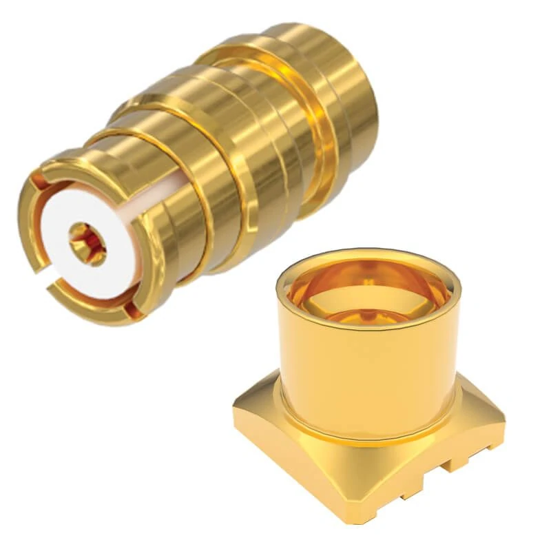
This SMP push-on RF test connector is designed for compact RF systems, high-frequency modules, and test fixture applications. The push-on structure supports quick mating and space-saving installation in RF measurement and microwave testing environments.
Many RF test problems start with a simple assumption: if two connectors can mate, they should work the same way.
That assumption usually holds at low frequencies. It becomes less reliable when the connection is part of a calibrated measurement path.
SMA connectors are common in RF laboratories because they are compact, available in many configurations, and compatible with a large number of test cables and adapters. But for measurement applications, the connector should be treated as part of the RF circuit rather than a separate hardware item.
The actual result depends on the complete assembly:
- SMA interface design
- Cable type and length
- Termination method
- Mounting structure
- Operating frequency
- Number of connection cycles
A connector that performs well in a prototype setup may require a different specification when moved into a production fixture.
How Can SMA Connectors Improve Test Fixture Repeatability?
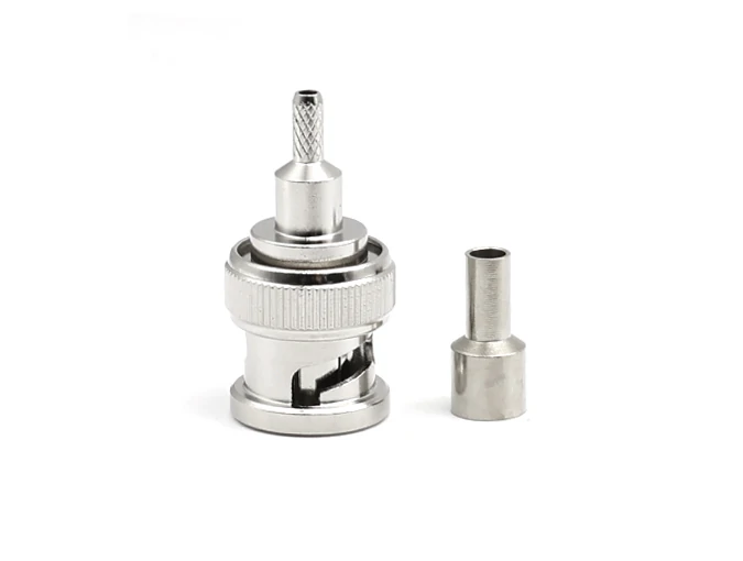
This BNC crimp RF connector is suitable for coaxial cable assembly, RF test cables, video signal transmission, and laboratory connection systems. The crimp design helps provide a secure cable termination for stable signal performance.
A test fixture has a different working environment from a normal electronic product.
The connector may be connected and disconnected many times every day. Operators may replace cables, change samples, or repeat measurements after calibration.
Under these conditions, mechanical consistency becomes as important as electrical specifications.
Typical applications include:
- RF module inspection fixtures
- Antenna testing platforms
- Communication equipment verification
- Laboratory calibration boards
The purpose is not simply to provide an RF port. The purpose is to create a predictable connection point.
For example, a production engineer may notice that measurements from two identical fixtures are slightly different. The first items usually checked are the instrument settings and software parameters. However, the connector mounting, cable routing, and mating condition can also contribute to the difference.
This is why test fixtures often use fixed mounting connectors instead of allowing the cable connector to move freely.
What Should Engineers Check Before Selecting an SMA Test Connector?
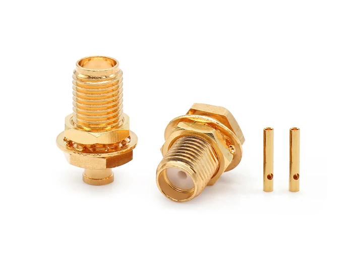
This SMA female bulkhead RF connector is used for fixed panel installation, RF test fixtures, communication equipment, and coaxial cable assemblies. Its bulkhead structure provides a stable connection point for repeated testing and reliable RF signal transmission.
Ordering an SMA connector only by saying “SMA 50Ω” leaves too many details undefined.
For test applications, the specification should normally include more information.
| Specification Item | Reason to Confirm |
| Connector gender | Prevents interface mismatch |
| Impedance | Maintains RF matching |
| Frequency range | Matches measurement band |
| Mounting style | Controls mechanical position |
| Cable compatibility | Avoids termination problems |
| Plating material | Affects contact durability |
| Test requirement | Defines inspection method |
A common sourcing issue is selecting a connector that matches the instrument but not the assembly process.
For example, an SMA connector designed for one cable diameter cannot simply replace another version with a different cable size.
The front interface looks identical. The RF result may not be.
When Should Engineers Choose SMA Bulkhead or Panel Mount Connectors?
The mounting method depends on how the RF connection is used.
An SMA bulkhead connector is generally considered when the interface needs to pass through an enclosure wall or fixture panel. It provides a fixed connection point and is convenient when the external cable needs frequent access.
An SMA panel mount connector is often selected when the connector becomes part of equipment integration.
The difference is not only mechanical.
The mounting structure affects:
- Connector alignment
- Installation stability
- Cable movement
- Long-term repeatability
A loose mechanical installation can gradually affect the mating condition. This may not appear during the first few measurements, but repeated testing can expose the problem.
For this reason, RF test fixture drawings usually define mounting hole size, panel thickness, connector orientation, and locking method before production.
How Should Engineers Evaluate Connector Frequency Range During Testing?
A connector frequency rating is only one part of the measurement system.
A frequent mistake in RF sourcing is focusing only on the connector specification while ignoring the rest of the signal path.
A test assembly may include:
- Instrument port
- Adapter
- Test cable
- Connector
- Device interface
Every additional transition can introduce loss or reflection.
This becomes more noticeable as frequency increases.
How Can Unsuitable Connectors Affect RF Measurement Results?
Some connector issues appear as measurement problems.
Typical examples include:
| Measurement Symptom | Possible Reason |
| Reading changes after reconnecting | Contact variation or wear |
| Unexpected VSWR increase | Interface mismatch |
| Higher insertion loss | Connector or cable loss |
| Calibration drift | Mechanical inconsistency |
A continuity test will not reveal these problems.
Continuity only confirms that the electrical path is connected. It does not show whether the RF impedance transition is controlled.
For RF test connectors, verification usually requires measurements such as:
- VSWR
- Return loss
- Insertion loss
- Repeatability testing
The connector should be evaluated under the same conditions where it will actually be used.
RF Test Connector Selection Decision Matrix
| Test Situation | Main Risk | Selection Focus |
| Laboratory prototype testing | Quick replacement | Interface compatibility |
| Production test fixture | Repeated mating | Mechanical durability |
| VNA calibration path | Measurement variation | Low reflection |
| Microwave measurement | Frequency limitation | Precision interface |
| Enclosed equipment test port | Installation movement | Bulkhead structure |
A connector chosen for testing is not just a component purchase. It is a measurement decision.
The right specification reduces uncertainty before the first sample reaches the bench.
RF Test Connector Selection Starts From the Measurement Condition
A connector drawing may show the correct thread size, plating, and interface type. That does not always mean the finished assembly will behave correctly in a measurement system.
A frequent situation in RF testing is that the first sample works well. The cable is installed, the instrument recognizes the connection, and the test result looks acceptable.
The problem appears later.
After repeated connection, after changing adapters, or after moving the fixture position, the measurement curve may shift slightly.
For RF test applications, the connector is part of the measurement path.
The final result is affected by several parts working together:
- Connector interface
- Cable structure
- Assembly process
- Mounting method
- Test frequency
- Connection frequency
A connector used in a laboratory calibration cable has a different working condition from a connector installed on an automated production fixture.
The specification should follow the actual usage.
How Does Connector Loss Appear During RF Measurement?
When a test system shows unexpected signal loss, replacing the connector is not always the first answer.
The complete RF route needs to be checked.
Each connection point changes the signal path.
The calculation itself is simple. The difficult part is finding which part creates the difference.
For example, two RF cables may use the same SMA connector.
One assembly uses a short cable with no adapter.
Another assembly uses a longer cable with several transitions.
The connector name is identical, but the measurement result may not be.
This is why RF purchasing documents usually need more information than a connector model.
A practical RF assembly specification may include:
| Item | Example |
| Interface | SMA Male / Female |
| Cable Type | RG316 / RG142 / Low Loss Cable |
| Length | 500 mm |
| Frequency | DC–6 GHz |
| Measurement | VSWR / Insertion Loss |
A clearer specification reduces replacement work after delivery.
Why Can VSWR Change Between Two Similar RF Connections?
VSWR problems are sometimes difficult to locate because the connector may still look normal.
The thread can be intact.
The cable can pass continuity.
The assembly can fit the equipment.
However, RF performance depends on the internal transition between components.
It only confirms that current can pass through the circuit.
For RF measurement, engineers normally need additional verification:
- VSWR measurement
- Return loss testing
- Insertion loss testing
A connector that passes electrical connection inspection may still require RF testing before being used in a precision measurement path.
How Are RF Test Connectors Used With VNA and Calibration Systems?
A VNA measurement is sensitive to changes in the connection environment.
During calibration, the instrument establishes a reference condition.
If the connector position changes after calibration, the measurement result may also change.
This is why laboratories often control:
- Cable movement
- Connector tightening method
- Adapter usage
- Connection sequence
The purpose is not simply to connect the equipment.
The purpose is to keep the measurement condition repeatable.
What Should Buyers Consider Before Selecting a Test Connector?
The connector interface is usually the first item buyers confirm.
Common choices include:
| Application | Common Interface |
| General RF testing | SMA |
| Microwave measurement | 2.92mm / 3.5mm |
| Outdoor communication equipment | N Type |
| Compact switching fixture | SMP |
But interface selection is only one step.
A buyer should also consider:
- How often the connector will be connected;
- Whether the connector is fixed or removable;
- Whether the cable needs frequent movement;
- Whether the test frequency is close to the connector limit.
A connector used several times a week and one used thousands of times on a production line should not share the same selection criteria.
What Changes After Thousands of RF Connector Mating Cycles?
RF connectors used in testing experience mechanical wear.
The changes may be gradual.
A connector may still connect normally while the measurement consistency begins to decline.
Typical concerns include:
- Contact wear
- Thread damage
- Surface contamination
- Alignment change
For production environments, some companies define inspection intervals based on usage.
The important point is not only how the connector performs when new.
It is how the connector behaves after repeated operation.
What Information Should Be Included in a Custom RF Test Connector Request?
Some testing fixtures cannot use standard connector structures directly.
A custom request may involve:
- Special mounting dimensions
- Limited installation space
- Fixed cable direction
- Existing equipment compatibility
A supplier normally needs both electrical and mechanical information.
A useful request example:
| Specification | Example |
| Connector Type | SMA Female |
| Application | RF Test Fixture |
| Impedance | 50Ω |
| Frequency | DC–18GHz |
| Mounting | Bulkhead |
| Finish | Gold Plated |
| Test Requirement | VSWR / Loss Test |
Providing fixture drawings or photos can reduce unnecessary modification cycles.
How Are RF Test Connectors Verified Before Shipment?
A connector can look perfect and still require electrical verification.
Inspection normally covers two areas.
Mechanical inspection checks:
- Thread condition
- Dimensions
- Mounting fit
- Surface condition
Electrical testing checks:
- VSWR
- Return loss
- Insertion loss
- Continuity
The inspection requirement depends on where the connector will be used.
A calibration cable and a general production fixture cable may not need the same acceptance standard.
RF Test Connector Acceptance Checklist
| Inspection Item | Verification Method |
| Connector Interface | Confirm mating type |
| Impedance | Verify 50Ω system |
| Frequency Range | Match test application |
| VSWR | Test at working frequency |
| Insertion Loss | Record measurement result |
| Mechanical Fit | Confirm fixture installation |
| Appearance | Check machining quality |
FAQ
Why are SMA connectors commonly used for RF testing?
SMA connectors provide a compact 50Ω interface and are available in many cable and mounting options. Their suitability depends on frequency and test conditions.
Is a higher frequency connector always better?
Not necessarily. The cable, adapter quantity, termination process, and installation condition also influence the final measurement.
When should a bulkhead RF connector be used?
A bulkhead connector is useful when the test interface needs a fixed position through a panel or enclosure.
Can a new RF test connector still cause unstable VNA results?
Yes, this can happen. A new connector only means the part has not been used before. The final measurement result is also affected by cable selection, adapter connection, fixture installation, and mating condition. If the RF path changes between tests, the VNA curve may also change.
What details should I confirm before ordering an RF test connector?
The connector interface is only one part of the specification. Before ordering, it is better to confirm the connector type, impedance, working frequency, cable requirement, mounting method, and expected test conditions. For fixture applications, installation dimensions and connection frequency are also worth defining in advance.