
A panel connector can pass a quick continuity check and still be the wrong part for the enclosure.
That mistake happens more often than buyers expect. The outside port looks like a normal SMA jack. The cable screws on. The nut tightens. Nothing looks obviously wrong. Then the RF test starts, or the unit goes into production, and the weak point appears: the rear cable has no bending room, the panel is too thick for the thread, or the mating side was ordered as standard SMA when the antenna system expected reverse polarity.
An SMA bulkhead connector should be treated as both a connector and a mounting component. It is the fixed RF pass-through between the outside of a device and the internal RF path. The electrical interface matters, but so do the hole size, panel thickness, washer stack, nut access, rear termination, and cable routing.
How Does an SMA Bulkhead Connector Create a Through-Panel RF Port?
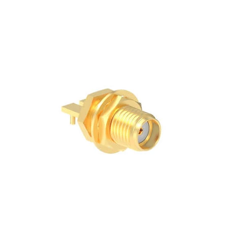
Compact SMA connector designed for PCB and panel integration. It supports RF signal transmission in wireless modules, communication equipment, and testing devices
The job of a bulkhead connector is simple on paper: carry the RF signal through a wall, metal panel, test fixture, shield box, or product housing. In the actual assembly, it has to hold position while cables are connected, disconnected, bent, tested, packed, and sometimes pulled by users who never read the drawing.
The outside interface is usually the visible side. For many products, that means an SMA female jack on the panel, ready to mate with an SMA male cable, antenna, adapter, or test lead. The inside side may be another SMA interface, a solder pin, a PCB transition, or a coax pigtail going to a module.
That inside structure is where many selection errors begin. A buyer may ask only for “SMA female bulkhead,” but that does not say enough. Does the internal side need a solder post? A cable tail? A right-angle exit? A rear nut? A gasket? A thread long enough for a thicker enclosure wall? Those details decide whether the part installs cleanly.
A bulkhead connector also changes how the RF path is handled in production. Instead of letting operators connect directly to a board-mounted connector or a loose cable inside the unit, the external cable mates with a fixed panel port. That protects the internal circuit from repeated handling. It also makes inspection easier because the port position is controlled.
But fixed does not automatically mean stable. If the connector is mounted at a slight angle, if the nut is not tightened evenly, or if the rear coax is forced into a tight bend, the assembly may still pass a basic electrical check while giving inconsistent RF behavior.
Continuity only proves that the center conductor and ground path are not open. It does not prove return loss, VSWR, insertion loss, shielding condition, or connector repeatability at the operating frequency. That difference matters more as the frequency rises.
Where the bulkhead structure helps
A properly specified SMA bulkhead port is useful when the RF connection must be repeatable. Common examples include antenna ports, GNSS receivers, Wi-Fi devices, RF test boxes, wireless modules, RF shield enclosures, and lab fixtures.
The main benefit is not just appearance. It is controlled access. The user connects to the panel, not to a fragile internal board or short cable. The enclosure takes the mechanical load, and the connector becomes part of the product’s serviceable interface.
This is also why a loose SMA adapter is not the same thing. An adapter can solve an interface mismatch during bench testing. It can also add mechanical leverage, extra interfaces, and another possible mismatch point. In a production product, a fixed bulkhead connector is usually easier to define, inspect, and repeat.
A useful RF port specification should name the interface, impedance, mounting style, internal termination, panel thickness range, hole size, and test requirement. “SMA connector” is too broad for production purchasing.
How Do You Pick Front-Mount or Rear-Mount Bulkhead Hardware?
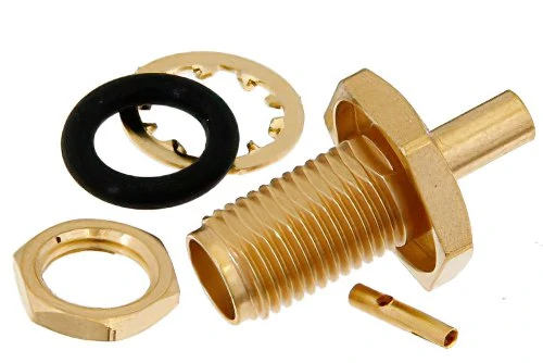
Disassembled SMA bulkhead connector components including mounting nut, washer, gasket, and contact parts. These components ensure secure mechanical mounting and reliable RF performance.
Mounting direction is one of the first details to settle. It affects not only how the connector looks from the outside, but also how the worker installs it.
A front-mount SMA bulkhead connector is normally installed from the outer side of the panel. This can make service easier because the nut or visible hardware may be accessible from the front. A rear-mount version is usually inserted from inside the enclosure, often giving a cleaner outside face but requiring enough internal space for tightening.
Neither option is automatically better. The correct one depends on the enclosure layout.
A front-access design may be convenient for test equipment or panels that need field replacement. A rear-access design may suit finished products where the outside surface must look clean or where the connector is installed before final enclosure assembly. In both cases, the installer still needs enough tool clearance. If the wrench cannot reach the nut cleanly, the connector may be left under-tightened or twisted during assembly.
The internal cable also needs protection during tightening. If the pigtail is already crimped or soldered, rotating the connector body can preload the cable, weaken the joint, or change the cable bend right at the connector exit. This is easy to miss during sample approval because one careful technician may build the sample by hand. Production workers will repeat the process faster.
| Mounting detail | What to check before ordering | Why it matters |
| Panel thickness | Thread length after washer and gasket | Too little thread can prevent secure nut engagement |
| Hole diameter | Drawing size, not estimated photo size | Oversized holes may allow tilt or movement |
| Nut access | Front or rear wrench clearance | Poor access leads to uneven tightening |
| Internal termination | Solder pin, adapter side, or cable pigtail | Rear layout decides cable bend and assembly process |
| Washer or gasket | Included parts and stack thickness | Extra parts reduce available thread length |
This table is not a replacement for a mechanical drawing. It is a quick way to catch the usual omissions before a purchase order is placed.
A second point is sealing. Some panel ports need only a nut and washer. Others need a gasket or O-ring because the connector sits on outdoor equipment, a vehicle-mounted enclosure, or a device exposed to dust and vibration. The gasket should be specified early because it adds thickness and changes the installed stack-up.
For purchasing, the safer request is specific:
SMA female bulkhead connector, 50 ohm, panel mount, standard SMA polarity, with nut and washer, suitable for the confirmed panel thickness and mounting hole, rear termination to be checked against drawing.
For cable versions, add the coax type and length:
SMA female bulkhead to internal coax pigtail, 50 ohm, specified cable type and length, exit direction confirmed, continuity test required, VSWR test if used near the target RF band.
That wording gives the supplier enough information to check the part instead of guessing from a product photo. It also gives the buyer a cleaner way to compare quotes. Two parts may both be called SMA bulkhead connectors, but the mounting hardware, internal termination, plating, insulator, and frequency rating may not be the same.
The small details decide whether the connector is only mountable, or actually suitable for the RF panel port.
How Should You Match SMA Female Bulkhead Interfaces With Mating Cables?
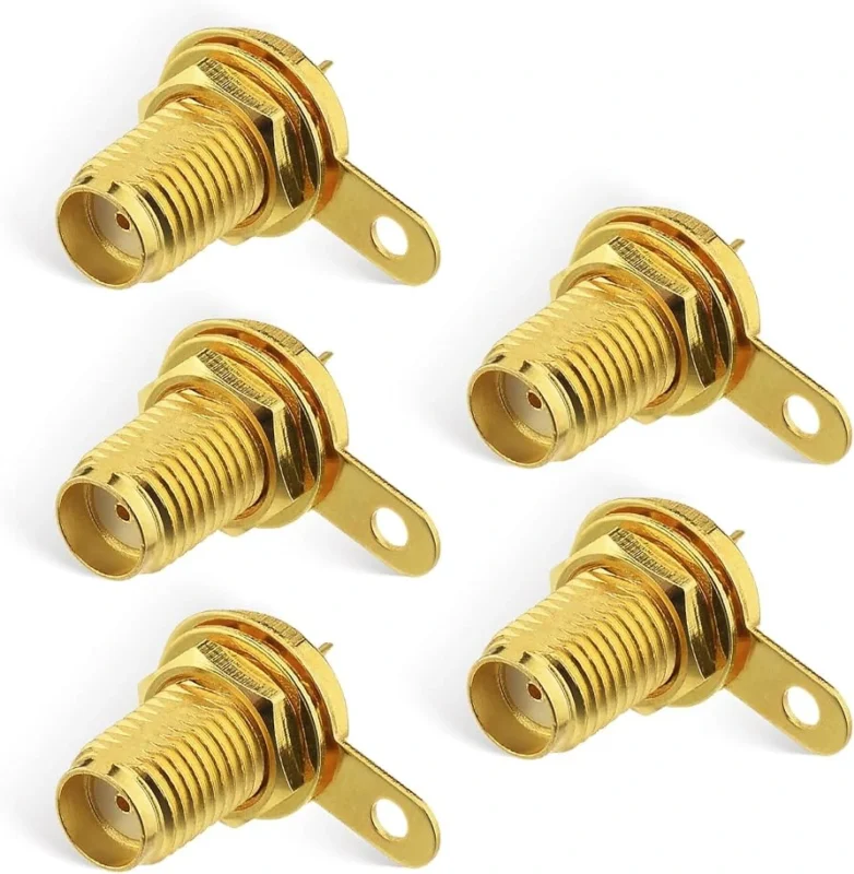
Most panel ports use an SMA female bulkhead connector on the outside because it gives the equipment a recessed center contact and a threaded interface for an SMA male cable, antenna, or adapter. That sounds straightforward until the buyer has to match the outside port, the inside termination, and the cable assembly in one order.
The first check is gender. SMA gender is not only about the thread. The center contact must also be checked. A standard SMA female jack normally has internal threads and a female center contact. A standard SMA male plug normally has external threads and a male center pin. Reverse-polarity versions change the center contact arrangement, and this is where antenna-port mistakes often start.
A product photo can mislead people. Some buyers look only at the shell and call the connector male or female by the thread. For RF purchasing, that is not enough. The mating side must be confirmed by thread and center contact together.
Confirm female jack structure before choosing the mating cable
An SMA female bulkhead jack is often selected for antenna ports, wireless modules, RF test points, and enclosure feedthroughs. It gives the user a fixed outside port, while the inside side can connect to a board, cable, module, or adapter.
But “female bulkhead” still leaves several unanswered questions.
The rear side may be a solder pin. It may be another SMA female or SMA male interface. It may be a short coaxial cable, such as RG316, RG174, RG178, RG405, or another cable chosen for the internal layout. A buyer replacing an old connector should not assume the rear structure from the front face. The same visible SMA jack can lead to very different internal builds.
A good drawing will show thread length, body length, insulator position, rear contact, nut position, and panel shoulder. Without that drawing, the supplier may quote a connector that mates correctly outside but cannot be installed inside the final enclosure.
Match the outer port with SMA male cables or adapters
For a standard SMA female bulkhead port, the usual mating cable is an SMA male cable assembly. That cable may connect to a VNA, antenna, RF module, splitter, attenuator, or another adapter. The cable should be selected by application, not only by connector name.
A short SMA male RG316 cable may work well for flexible internal or test connections. A thicker cable such as RG58 or RG142 may be better when the assembly needs lower loss or stronger handling, but those cables need more bend space. A small enclosure that accepts RG316 neatly may not accept RG58 without forcing the cable path.
The connector body must also match the cable. An SMA plug made for RG316 should not be treated as interchangeable with one made for RG58. The ferrule, rear body, dielectric support, and crimp area are different. A cable can be assembled tightly and still be mechanically wrong if the connector was not designed for that cable size.
| Interface or cable detail | Correct check | Common sourcing mistake |
| Outside bulkhead port | Confirm SMA gender and polarity | Judging only from thread appearance |
| Mating cable | Match SMA male or female interface correctly | Ordering the cable by connector name only |
| Internal termination | Check solder pin, rear SMA, or pigtail style | Assuming all bulkhead jacks have the same rear side |
| Cable type | Match connector body and ferrule to cable OD | Using RG316 hardware on larger coax |
| Antenna port | Confirm standard SMA or RP-SMA | Mixing SMA and RP-SMA in Wi-Fi antenna systems |
| Test port | Check frequency and repeat mating needs | Using a low-grade port in repeated lab testing |
This table is useful during RFQ review. It forces the buyer to describe the real mating condition instead of sending a short line like “need SMA bulkhead connector.”
Avoid standard SMA and RP-SMA confusion in antenna ports
Antenna ports create more confusion than lab test ports because many wireless products use reverse-polarity SMA. The outside shape may look familiar, but the center contact arrangement may not match a standard SMA cable.
This mistake is easy to catch before ordering and expensive to fix after assembly. If the customer says the part is for Wi-Fi, router, IoT gateway, antenna extension, or wireless enclosure, ask for a photo of the mating antenna or the existing port. A drawing is better. A sample is better still.
Do not rely only on “male” and “female” wording from the end user. Many non-RF buyers describe the connector by the shell or by the cable they already have. For production, write the polarity into the BOM.
A safer BOM line would read:
SMA female bulkhead connector, standard polarity, 50 ohm, panel mount, outside port mates with standard SMA male cable, rear termination confirmed by drawing.
For reverse-polarity use, write RP-SMA clearly. Do not hide it in notes.
How Do Panel Thickness and Hole Size Affect Installation?
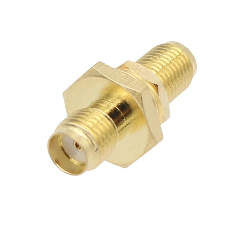
SMA female bulkhead adapter designed for mounting through equipment panels and enclosures. The threaded body allows secure installation while maintaining a 50 ohm RF signal path.
Panel installation looks like a mechanical detail, but it changes the final RF connection. If the connector moves, tilts, or cannot be tightened correctly, the RF path becomes less repeatable.
The two basic dimensions are panel hole diameter and panel thickness. Both should come from the connector drawing. Estimating from a photo is risky because the thread, shoulder, washer, and gasket may all change the installed fit.
A hole that is too small simply blocks installation. A hole that is too large is worse in a quieter way. The connector may fit, but the body can shift before tightening. That makes the port less centered, changes washer pressure, and may leave the connector slightly angled.
Measure panel thickness before confirming thread length
Panel thickness is not only the metal sheet thickness. The real stack may include paint, plating, gasket, washer, lock washer, and sometimes an extra sealing part. Each layer uses thread length.
If the remaining thread is too short, the nut may catch only a few turns. That can pass a sample build and still loosen in transport or field use. If the thread is much longer than needed, it may interfere with nearby parts or leave a rough rear-side layout.
For thin aluminum panels, many standard bulkhead parts work without trouble. For thicker housings, molded enclosures, waterproof boxes, or powder-coated panels, the buyer should confirm the full stack-up before ordering.
Verify mounting hole diameter with the product drawing
The hole size should not be guessed from the thread diameter alone. Some bulkhead connectors have a shoulder, flat, key, gasket seat, or washer area that affects the required opening. The drawing should state the recommended panel cutout.
For replacement parts, measure the old connector and the existing hole separately. A caliper measurement of the old thread is useful, but it does not always tell you the designed panel hole. If the old part was loose, damaged, or modified, copying it may repeat the same problem.
Use this installation checklist before releasing a purchase order or machining a panel:
| Check field | Required confirmation | Risk if missed |
| Panel hole diameter | Drawing value in mm or inch | Loose fit, tilt, or no installation |
| Panel thickness | Full stack after coating and gasket | Not enough thread for nut |
| Thread length | Must exceed usable panel stack | Weak mechanical hold |
| Nut clearance | Tool space on selected side | Under-tightening or cable twist |
| Washer / lock washer | Included and positioned correctly | Loosening during vibration |
| Gasket / O-ring | Needed or not needed | Poor sealing or wrong stack-up |
| Inside cable direction | Straight, right angle, or pigtail | Sharp bend behind panel |
| Final inspection | Visual, continuity, RF test if required | Hidden assembly variation |
This is the kind of information that saves time during quotation. It also reduces supplier guesswork. If the supplier only receives a front-facing photo, the quote may be mechanically incomplete.
Leave enough clearance for nut tightening and cable bending
Rear clearance is often the last thing checked. It should be checked early.
The nut needs space for a socket or wrench. The cable needs space for a natural bend. The operator needs enough room to install the connector without twisting the rear termination. If the port sits too close to a wall, PCB, battery, heat sink, or another connector, the build may become slow and inconsistent.
The cable bend is especially sensitive near the connector exit. A tight bend can pull on the crimp, disturb braid contact, or create stress at a solder joint. The failure may not appear immediately. It may show up after the enclosure is closed, after vibration, or after the cable has been moved during service.
For TEJTE-style RF sourcing, the best inquiry includes a simple rear-view photo or layout note: panel thickness, expected hole size, inside available depth, cable type, cable length, and the direction the internal cable should leave the connector.
That information is small. It changes the quote from a connector guess into an RF panel-port selection.
How Can You Control RF Loss and VSWR in Bulkhead Connections?
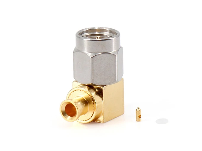
A right angle SMA RF connector shown with connector components, designed for compact RF assemblies where cable direction and space limitations need to be considered.
A bulkhead port adds one more interface to the RF path. That is not a problem by itself. The problem starts when the interface is treated as a purely mechanical part.
The connector may be marked 50 ohm, but the installed port still depends on the mating cable, center contact condition, panel alignment, tightening consistency, and rear termination. A clean connector mounted badly can test worse than an ordinary connector mounted correctly.
For general RF equipment, start with the known limits: impedance, frequency range, connector type, cable type, and expected test standard. Do not approve the connector only because the thread fits. The SMA interface, rear transition, and cable assembly must work together.
Confirm 50 ohm impedance before selecting the connector
Most SMA connectors used in RF equipment are 50 ohm. That should still be written into the RFQ and BOM. If the part is replacing an existing connector, do not assume the impedance from appearance alone.
The bigger mistake is thinking that 50 ohm on the connector solves the whole RF path. It does not. The cable, adapter, PCB transition, solder joint, and mating connector all affect the result. A bulkhead connector used with a poor rear cable exit can still show unstable return loss.
Check frequency rating for high-frequency equipment
Frequency rating should have margin. A connector used at 5.8 GHz does not need to be rated for every microwave application, but it should not be operating blindly at the edge of an unknown specification.
For simple antenna ports, a standard SMA bulkhead connector may be enough. For test fixtures, microwave modules, or measurement panels, the buyer should ask for the rated frequency and test condition. A port that is connected and disconnected every day should also be judged by mechanical repeatability, not only by the first test result.
Reduce reflection by avoiding loose mating and damaged contacts
High VSWR is often blamed on the connector first. Sometimes that is correct. Sometimes the real cause is a bent center contact, loose nut, tilted panel mount, dirty mating surface, tight cable bend, or an adapter stack added after the design was tested.
Use a simple risk screen before production approval:
| Risk factor | Lower-risk condition | Higher-risk condition |
| Impedance | 50 ohm confirmed | Unknown or not stated |
| Frequency | Clear margin above working band | Near unknown upper limit |
| Mating face | Clean thread and center contact | Worn, bent, dirty, or loose |
| Panel mount | Firm, square, repeatable | Tilted or moves before tightening |
| Rear cable | Natural bend radius | Forced bend near connector exit |
| Test result | Continuity plus RF test if required | Continuity only |
This is not a lab standard. It is a practical purchasing filter. It helps decide when a low-risk catalog part is enough and when a drawing, sample, or VNA check should be requested before mass production.
How Do Bulkhead SMA Connectors Work With Cable Assemblies?
Many enclosure designs use a bulkhead-to-cable assembly rather than a standalone connector. The outside face becomes the SMA panel port. The inside cable connects to a PCB, radio module, antenna circuit, switch, attenuator, or test board.
That layout is convenient, but it moves part of the RF risk into the cable assembly.
A short flexible cable may be easier to install. A thicker low-loss cable may reduce attenuation, but it needs more space and a larger bend radius. A semi-rigid or semi-flex cable may hold shape better, but it is less forgiving during assembly. The best choice depends on the actual enclosure, not only the frequency.
For purchasing, cable type must be named clearly. “SMA cable” is too vague. A useful description would include cable family, length, impedance, connector A, connector B, polarity, mounting style, and test requirement.
Example:
SMA female bulkhead to SMA male cable assembly, 50 ohm, RG316 coax, 200 mm length, standard SMA polarity, panel mount with nut and washer, continuity test required, VSWR test at target frequency if needed.
That sentence gives the supplier something real to build and inspect.
How Should You Inspect an SMA Bulkhead Connector Before Installation?
Inspection should happen before the connector is locked into the panel. After installation, some problems become harder to see.
Start with the visible parts: thread, plating, center contact, insulator, nut, washer, lock washer, and gasket. The center contact should not be bent, recessed, loose, or contaminated. The thread should screw smoothly with the mating connector.
For cable assemblies, also check the crimp area, heat shrink, cable jacket, strain relief, and label. If the cable exits at an angle that does not match the enclosure layout, stop before tightening it into the product.
A basic acceptance check may look like this:
| Inspection item | Acceptance requirement |
| Interface | Correct SMA gender and polarity |
| Mounting hardware | Nut, washer, gasket if required |
| Thread | No visible damage or poor engagement |
| Center contact | Not bent, pushed back, or loose |
| Insulator | No crack, melt mark, or deformation |
| Cable termination | No loose crimp, broken braid, or exposed defect |
| Electrical check | Continuity passed, no short |
| RF check | VSWR or insertion loss test if required by application |
A sample approval should record more than “OK.” Record the drawing version, panel thickness, cable type, test frequency, and any special assembly note. That protects repeat orders.
How Do You Specify an SMA Bulkhead Connector for Purchasing?
A good RFQ removes guessing. The supplier should not have to decide the polarity, rear termination, hole size, cable type, or test level from a single photo.
Use this information when sending a request:
- SMA gender and polarity
- 50 ohm impedance
- front-mount or rear-mount style
- panel thickness and hole size
- nut, washer, lock washer, gasket needs
- rear termination type
- cable type and length, if it is an assembly
- operating frequency or test frequency
- quantity and packaging requirement
- drawing or sample photo for replacement work
For TEJTE orders, photos are useful for quick identification. Drawings are better for production. Samples are the safest when the connector replaces an old part from an existing enclosure.
FAQ
Does an SMA bulkhead connector always need a mounting nut?
Most bulkhead designs use a nut and washer to lock the connector to the panel. Some designs may also use a lock washer, gasket, O-ring, or special mounting shoulder. Check the drawing before ordering, especially if the connector must pass through a thick panel or sealed enclosure.
Is an SMA bulkhead connector the same as an SMA panel mount connector?
They are related, but not always identical. Bulkhead usually means the connector passes through a panel or enclosure wall. Panel mount can include several fixed mounting styles, including flange mount, threaded bulkhead, PCB-supported panel mount, or cable pigtail versions.
Can an SMA female bulkhead connector be used as an antenna port?
Yes. It is commonly used as an external antenna port when the mating antenna or cable uses the correct SMA male interface. For Wi-Fi or wireless antenna products, confirm whether the system uses standard SMA or RP-SMA before purchase.
How do I choose the correct hole size?
Use the manufacturer’s drawing. Do not estimate from the thread diameter or product photo. The correct hole may depend on the connector shoulder, washer, gasket, panel thickness, and whether the design needs anti-rotation or sealing features.