
A connector can fit the panel opening and still create problems later.
This happens more often than many buyers expect. The SMA interface looks correct, the thread mates normally, and the first bench test shows continuity. The issue appears when the connector becomes part of a finished enclosure, exposed to repeated mating, vibration, cable pulling force, or higher-frequency measurement.
A SMA bulkhead connector is often selected because the equipment needs a fixed RF access point through a chassis or panel. However, the mounting method, cable connection, frequency range, and mechanical dimensions all affect the final RF path. A connector that works on a prototype bench may not be the right choice for a production enclosure.
For RF equipment manufacturers, the key question is not only “Can the SMA connector connect?” It is “Can the connector maintain the expected electrical and mechanical behavior after installation?”
Why Are SMA Bulkhead Connectors Used in RF Equipment?
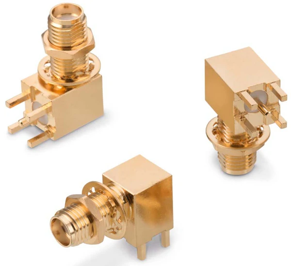
These SMA PCB mount connectors are used for RF circuit board integration where a stable board-level RF interface is required. The right angle structure supports compact layouts and is suitable for RF modules, test instruments, communication boards, and antenna connection designs.
An SMA bulkhead connector is commonly used when an RF system requires an external connection point on an enclosure wall, panel, or chassis. Unlike a standard cable-mounted SMA connector, the bulkhead version includes a mounting structure that allows the connector body to pass through a panel and remain mechanically fixed.
This installation style is common in equipment where operators or technicians need repeated access to the RF port.
Typical applications include:
- RF test equipment
- communication devices
- wireless modules
- antenna interface panels
- laboratory measurement fixtures
- outdoor communication enclosures
The main reason engineers select a bulkhead structure is repeatability. A loose cable connector moves with the cable assembly. A panel-mounted connector creates a defined interface location, making equipment assembly, maintenance, and testing easier.
Understand how bulkhead mounting improves RF system integration
The connector is only one section of the signal path.
This is a common sourcing issue. Buyers sometimes specify only the front interface, such as “SMA female,” while ignoring the rear structure. For production assemblies, details such as cable compatibility, mounting thickness, and termination method should be included in the BOM.
Identify when a fixed RF interface is required
Bulkhead mounting is useful when the RF connection will be accessed repeatedly.
Compared with a free cable end, a fixed bulkhead interface provides:
| Requirement | Bulkhead Connector Advantage |
| Equipment assembly | Defined mounting position |
| Repeated connection | Reduced cable movement |
| Maintenance access | Easier replacement |
| External RF port | Cleaner enclosure design |
| Test connection | Consistent measurement point |
A test engineer working with network analyzers or calibration fixtures may connect and disconnect the same RF port hundreds of times. In this situation, mechanical stability becomes part of measurement consistency.
The connector thread, panel fit, and mounting hardware all contribute to long-term usability. A connector that is slightly loose after installation can create unnecessary stress on the RF cable and affect the connection repeatability.
Connect bulkhead connectors with complete RF signal paths
Selecting the SMA interface alone is not enough. Engineers should consider the entire assembly:
| Item | Specification to Confirm |
| Connector interface | SMA male or SMA female |
| Impedance | 50Ω RF system |
| Cable type | RG316, RG58, RG142, semi-rigid cable, etc. |
| Frequency range | Match operating frequency |
| Mounting method | Bulkhead through-panel installation |
| Termination | Crimp, solder, or custom assembly |
For example, a small RG316 cable assembly may be suitable for compact RF modules, while a larger RG58/RG142 assembly may be preferred when mechanical strength or lower attenuation is required.
The connector body and cable should be treated as one RF component, not separate purchasing items.
SMA Bulkhead Connector Application Map
| Application | Installation Requirement | Selection Focus |
| RF Test Equipment | Frequent connection cycles | Mechanical stability and VSWR testing |
| Communication Device | External RF access port | Panel compatibility |
| Equipment Enclosure | Through-wall mounting | Hole size and panel thickness |
| Antenna System | Outdoor or external connection | Cable routing and protection |
| Laboratory Setup | Repeatable measurement access | Connector consistency |
A practical rule for procurement teams is to describe the connector from the equipment side, not only from the connector side.
Instead of writing:
“SMA female connector”
a clearer BOM description would include:
“SMA female bulkhead connector, 50Ω, through-panel mounting, specified frequency range, compatible cable type, required termination method.”
This small change reduces substitution mistakes and gives suppliers enough information to evaluate the RF path.
For custom projects, especially RF test equipment and communication hardware, the mounting details should be confirmed before mass production. A connector that looks identical externally may have different internal dimensions, dielectric structure, or cable compatibility.
The next section will compare SMA bulkhead connectors with other SMA mounting styles and explain when engineers should choose bulkhead, panel mount, or flange mounting structures.
How Does an SMA Bulkhead Connector Differ From Other SMA Mounting Styles?
A connector drawing can look simple until it is installed into the actual equipment.
Many SMA connectors share the same front interface, but the rear structure determines how they are fixed, what cable can be attached, and how the assembly behaves after installation. This is where bulkhead, panel mount, flange mount, and cable-mounted SMA connectors begin to differ.
For engineers selecting components for an enclosure, choosing the mounting style first can prevent later mechanical changes.
An SMA bulkhead connector is mainly designed for through-panel installation. This creates an external RF interface while keeping the internal connection accessible.
A standard cable SMA connector does not provide this fixed mounting function. It depends on the cable assembly for physical support.
Compare bulkhead, panel mount, and flange mounting methods
The terms “bulkhead” and “panel mount” are sometimes used interchangeably in RF purchasing documents. However, there can be differences depending on the connector manufacturer’s naming method.
A panel mount connector generally describes any connector fixed to a chassis or panel. A bulkhead connector specifically emphasizes a structure that passes through the panel or enclosure wall.
The selection should be based on the mechanical requirement, not only the product name.
| Mounting Style | Structure | Typical Application | Main Consideration |
| Cable SMA | Connector terminated directly on coax cable | RF jumper, internal connection | Cable support and routing |
| Panel Mount SMA | Fixed to equipment panel | RF enclosure interface | Mounting hole and panel thickness |
| Bulkhead SMA | Through-panel mounting structure | External RF access port | Front/rear clearance |
| Flange SMA | Screw-fixed flange body | Test fixture and precision equipment | Multiple fixing points |
For a communication device with an external antenna port, a bulkhead SMA connector may provide a cleaner installation compared with leaving a cable assembly hanging from the enclosure.
For laboratory equipment, flange mounting may become more suitable because multiple screws provide additional mechanical fixation. This is often seen in fixtures where alignment stability is more important than compact installation.
Choose bulkhead mounting for chassis and enclosure applications
A common mistake during sourcing is selecting a connector only by interface type.
A buyer may request:
“SMA female, 50Ω”
These details affect the final connector structure.
For example, an SMA female bulkhead connector installed on a thin aluminum panel may require a different body length compared with one installed on a thicker equipment housing.
The mounting hole also needs attention. A connector may physically fit the diameter, but the rear nut, washer, cable exit direction, or internal clearance can still prevent proper assembly.
In production environments, small mechanical differences can create assembly problems:
- connector body cannot fully seat against the panel;
- internal cable bends beyond the recommended radius;
- tightening torque damages the panel surface;
- cable stress transfers directly to the connector joint.
These problems are usually discovered after the enclosure design is already complete.
Understand when flange mounting is more suitable
Flange-mounted SMA connectors use screw fixation rather than a single threaded mounting nut.
The choice between bulkhead and flange mounting is not about which structure is better. It depends on the equipment requirement.
A portable communication enclosure may benefit from the compact installation of a bulkhead connector. A laboratory calibration fixture may require the stronger positioning of a flange structure.
How Do You Select the Right SMA Female Bulkhead Connector?
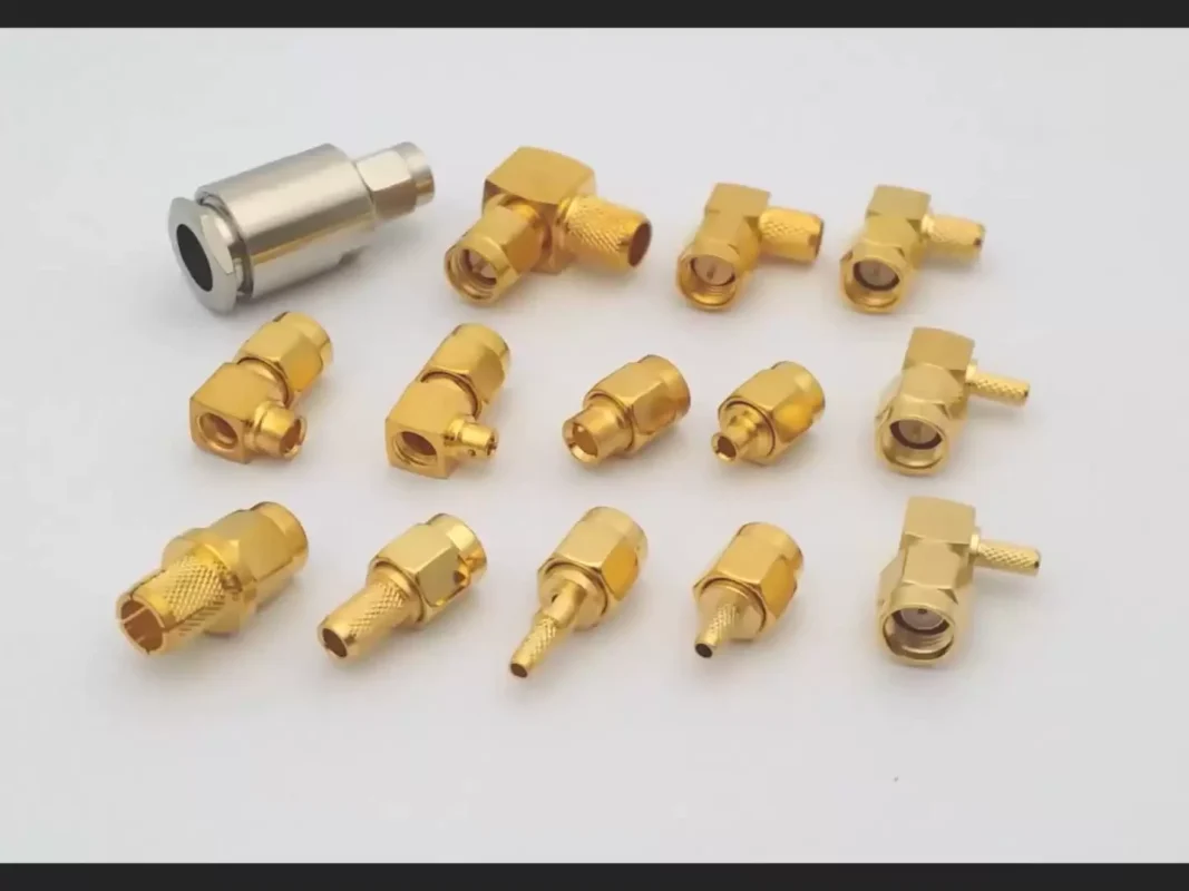
The phrase “SMA female bulkhead connector” describes only the basic interface. A complete selection requires checking mechanical, electrical, and application requirements together.
A connector can have the correct SMA female interface but still fail the project requirement because of frequency limitation, incorrect mounting dimensions, or unsuitable cable compatibility.
Confirm connector gender and interface requirements
SMA connectors use a threaded coupling design, but gender identification includes both the outer mechanical interface and the center contact.
Typical SMA definitions:
| Interface | Center Contact | Common Description |
| SMA Male | Pin contact | Plug |
| SMA Female | Socket contact | Jack |
When ordering SMA bulkhead connectors, buyers should also confirm whether the project requires:
- standard SMA polarity;
- reverse polarity SMA (RP-SMA);
- cable-side gender;
- external mating interface.
SMA and RP-SMA may look similar externally, but they are not interchangeable in RF systems.
This is a frequent mistake in antenna-related projects. The connector may physically screw together but the internal contact structure does not match.
Match mounting dimensions with equipment design
Mechanical drawings should be reviewed before production approval.
Important dimensions include:
| Parameter | Why It Matters |
| Panel thickness | Determines body length and fixing method |
| Mounting hole diameter | Ensures correct installation |
| Connector length | Affects internal clearance |
| Thread position | Affects external mating space |
| Cable exit direction | Influences routing |
For custom assemblies, providing a panel drawing or 3D model can reduce unnecessary sample adjustments.
A connector supplier may have several SMA bulkhead options that appear similar in catalog photos, but the rear dimensions can differ significantly.
Verify electrical specifications before selection
The RF specification should be matched with the actual operating condition.
Key parameters include:
- impedance;
- frequency range;
- VSWR;
- insertion loss;
- power requirement.
Most SMA RF connectors are designed for 50Ω systems. However, the connector rating alone does not define the entire assembly performance.
For example, a short SMA bulkhead connection used below its rated frequency may perform differently from a longer cable assembly operating close to the upper frequency limit.
SMA Bulkhead Connector Selection Checklist
| Parameter | Requirement to Confirm |
| Connector Gender | SMA Female / SMA Male |
| Mounting Style | Bulkhead through-panel |
| Impedance | 50Ω RF system |
| Frequency | Match operating band |
| Panel Thickness | Confirm enclosure dimension |
| Cable Interface | RG316 / RG58 / RG142 / semi-rigid cable |
| Termination | Crimp, solder, or custom assembly |
| Test Requirement | VSWR, insertion loss, continuity |
This checklist can be used directly in an RF purchasing request.
A complete RF specification reduces communication cycles between engineering teams and suppliers. It also prevents a common issue in connector sourcing: receiving a mechanically compatible part that does not match the intended RF application.
In the next section, we will continue with SMA bulkhead connector RF performance factors, testing methods, custom specification requirements, and delivery inspection standards.
How Does SMA Bulkhead Connector Design Affect RF Performance?
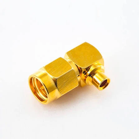
This right angle SMA male connector is suitable for coaxial cable assemblies where installation space is limited. The 90-degree design helps reduce cable bending stress while supporting stable RF signal transmission in modules, instruments, and communication equipment.
A bulkhead connector may be mechanically installed correctly and still create RF problems.
This situation is common during product development. The connector fits the enclosure, the cable is assembled correctly, and continuity testing passes. However, when the equipment moves into higher-frequency operation, unexpected VSWR changes or insertion loss appear.
The reason is that RF performance depends on the complete transmission path.
A connector should not be evaluated only by its appearance or thread compatibility.
Maintain 50Ω impedance through the RF connection
Most SMA RF applications use a 50Ω impedance system.
The purpose of maintaining impedance consistency is to reduce unwanted signal reflection when the RF wave travels through different components.
An impedance discontinuity may increase:
- return loss;
- reflected signal;
- VSWR;
- measurement variation.
For a bulkhead connector, the internal geometry matters.
Important design factors include:
- center pin alignment;
- dielectric material;
- contact spacing;
- outer conductor structure;
- connection interface accuracy.
A small mechanical difference inside the connector may not be visible from the outside but can influence performance at higher frequencies.
This is why two SMA bulkhead connectors with the same external dimensions may not always provide identical RF results.
Evaluate frequency capability for high-frequency applications
Frequency selection is often underestimated during procurement.
A connector rated for a specific frequency range should be evaluated against the actual operating environment, not just the nominal system frequency.
For example:
- a low-frequency control application may have wide tolerance;
- an RF test fixture operating near the upper GHz range requires more attention;
- a measurement cable used for calibration may require additional frequency margin.
A useful selection method is:
Frequency Margin Ratio = Connector Rated Frequency ÷ Maximum Operating Frequency
| Frequency Margin Ratio | Application Guidance |
| ≥1.2× | General RF connection |
| ≥1.5× | More suitable for test cables and repeated measurements |
| ≥2.0× | Preferred for sensitive RF measurement systems |
This is not a replacement for actual testing, but it helps buyers avoid selecting components too close to the operating limit.
The connector frequency rating should also be considered together with:
- cable attenuation;
- cable length;
- number of adapters;
- mating frequency;
- installation environment.
A higher-frequency connector does not automatically improve the entire assembly if the cable or termination becomes the limiting factor.
Reduce RF loss through proper connector matching
Insertion loss is affected by the whole RF path.
Common factors include:
- connector interface quality;
- cable type;
- assembly process;
- contact resistance;
- mechanical stress.
For example, using an SMA bulkhead connector designed for a small flexible cable on a larger coaxial cable may create mechanical and electrical mismatch.
Cable compatibility is especially important for production orders.
A BOM description such as:
“SMA bulkhead connector”
does not provide enough information.
A better specification would include:
“SMA female bulkhead connector, 50Ω, for RG316 cable, specified frequency range, gold-plated contact, PTFE dielectric, required VSWR inspection.”
This gives the supplier enough information to select the correct structure.
How Are SMA Bulkhead Connectors Used in RF Testing Applications?
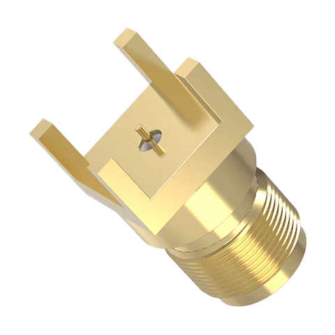
This SMA bulkhead jack connector is designed for fixed panel mounting in RF equipment. The threaded interface supports secure mating, while the bulkhead structure provides a stable external RF port for antenna interfaces, test fixtures, and communication enclosures.
RF testing environments place different requirements on connectors compared with normal equipment connections.
A communication device may connect an antenna once during installation. A test fixture may connect and disconnect hundreds or thousands of times.
The connector must maintain mechanical consistency while keeping electrical characteristics stable.
Apply bulkhead connectors in measurement equipment
SMA bulkhead connectors are commonly integrated into:
- network analyzer fixtures;
- signal generators;
- RF evaluation boards;
- calibration panels;
- laboratory test equipment.
In these applications, repeatability is often more important than simply achieving a connection.
A loose mounting point can introduce measurement variation. A damaged thread can change mating conditions. A worn contact can increase uncertainty during testing.
Improve repeatability in frequent RF connections
For test applications, engineers should consider:
- connector mating cycles;
- mounting strength;
- torque control;
- thread durability;
- cleaning procedure.
The connector panel mounting should prevent unnecessary movement during operation.
A practical inspection process may include:
| Inspection Item | Purpose |
| Thread check | Confirm mating quality |
| Panel fit inspection | Verify mechanical installation |
| Continuity test | Confirm electrical connection |
| VSWR test | Check RF matching |
| Insertion loss test | Evaluate signal loss |
| Mechanical cycle test | Verify repeated use |
Continuity testing alone is not enough.
A connector can pass a basic electrical connection test while still showing poor RF behavior at operating frequency.
How Should Engineers Specify Custom SMA Bulkhead Connectors?
Custom RF connector projects usually fail because the specification starts too late.
A supplier needs more than a product name. The mechanical design, electrical target, and assembly environment should be defined before production.
Define mechanical requirements before manufacturing
Important mechanical information includes:
- mounting hole size;
- panel thickness;
- installation direction;
- external thread requirements;
- internal clearance;
- cable routing space.
For equipment manufacturers, a drawing is usually more effective than a product description.
A simple specification such as “need SMA female bulkhead” may leave several possible interpretations.
Provide RF electrical requirements
Electrical requirements should include:
- impedance;
- operating frequency;
- VSWR target;
- insertion loss requirement;
- power handling;
- test method.
For example:
| Field | Example Requirement |
| Connector Type | SMA Female |
| Mounting | Bulkhead |
| Impedance | 50Ω |
| Frequency | DC–12.4 GHz |
| Material | Brass |
| Plating | Gold plated contact |
| Application | RF Test Equipment |
This type of RF request allows suppliers to evaluate the connector structure instead of matching only a catalog image.
How Should SMA Bulkhead Connectors Be Tested Before Delivery?
A production connector should be checked from both electrical and mechanical perspectives.
Verify electrical performance across the operating range
Common RF inspection items include:
- VSWR;
- return loss;
- insertion loss;
- continuity.
For high-frequency applications, testing should be performed under conditions close to the final usage environment.
For example, a cable assembly tested in a straight position may behave differently after installation inside a compact enclosure with tight bending.
Inspect mechanical mounting accuracy
Mechanical inspection should confirm:
- thread quality;
- connector position;
- panel fit;
- surface finish;
- fixing strength.
Small dimensional differences may create assembly problems during mass production.
Confirm long-term connection reliability
For equipment requiring repeated operation, engineers should consider:
- mating cycles;
- mechanical durability;
- connector cleaning;
- cable strain relief.
A stable RF interface is not only about the first successful connection. It is about maintaining the same condition after repeated use.
SMA Bulkhead Connector Acceptance Checklist
| Inspection Item | Requirement |
| Interface | SMA confirmed |
| Mounting | Correct bulkhead installation |
| Impedance | 50Ω verified |
| Frequency | Application range confirmed |
| VSWR | Tested |
| Insertion Loss | Verified |
| Mechanical Fit | Confirmed |
| Appearance | Passed inspection |
This checklist can be included in supplier quality requirements or incoming inspection documents.
FAQ
Are SMA bulkhead connectors always 50Ω?
Most RF SMA bulkhead connectors are designed for 50Ω systems. However, the specification should be verified because RF connector families may include different impedance versions for specific applications.
Can SMA bulkhead connectors be customized?
Yes. Custom options may include mounting dimensions, cable compatibility, plating requirements, connector materials, and electrical specifications.
Why can’t I use the same SMA bulkhead connector for different coaxial cables?
Because the rear side of the connector is built around a specific cable structure.
RG316, RG58, and RG142 cables have different outside diameters, shielding structures, and termination requirements. An SMA bulkhead connector that works well with a small flexible cable may not provide the correct mechanical support for a larger coaxial cable.
In production, the front SMA interface is only the starting point. The cable, connector body, and assembly method need to work as one RF path.
What details should I send when requesting an SMA bulkhead connector quotation?
A simple request such as “need SMA female bulkhead connector” usually leaves too many details open.
A supplier will normally need information such as connector gender, impedance, operating frequency, mounting thickness, cable model, termination method, and whether RF testing is required.
For example, an RF test fixture and an outdoor antenna enclosure may both use SMA connectors, but the mechanical design and inspection requirements can be completely different.
Final Practical Note
Selecting an SMA bulkhead connector is not only a matter of matching the SMA interface.
The better approach is to define the complete RF path:
- where the connector will be installed;
- what cable will be attached;
- what frequency range is required;
- how often the connector will be mated;
- what inspection standard is expected.
For production projects, providing these details before ordering samples usually saves more time than correcting a connector mismatch after assembly.
If the RF assembly operates near the upper frequency limit, share the operating frequency, cable type, length, connector quantity, and test requirements before final selection. This information helps determine whether a standard SMA bulkhead connector is sufficient or whether a different structure should be considered.
