
A cable can pass continuity and still be the wrong RF part.
That is usually where the problem starts. The sample looks fine. The connector fits the device port. The cable length is close enough. Then the assembly is installed inside an enclosure, bent behind a panel, or tested near the upper operating band. Suddenly the loss is higher than expected, VSWR is unstable, or the production team finds that the connector body does not match the cable diameter.
An RF cable assembly should not be treated as “just a coax cable with two connectors.” It is a connectorized RF signal path. The connector interface, cable type, length, impedance, termination method, shielding, bend radius, and inspection requirement all affect whether the assembly will behave correctly in the final system.
How Should an RF Cable Assembly Be Defined Before Quotation?
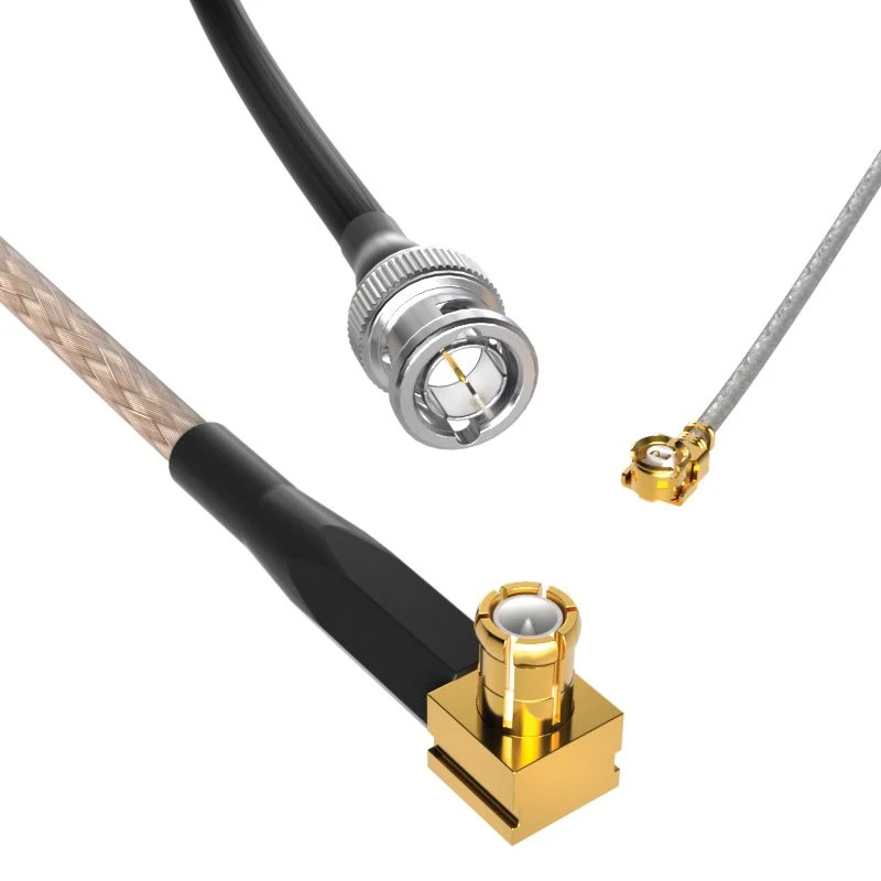
Miniature RF cable assemblies are designed for compact wireless devices, GPS modules, IoT equipment, and PCB applications. TEJIATE supports customized micro coaxial cables, connector types, and cable lengths.
The fastest RFQ is not always the clearest RFQ.
A buyer may send a message such as “Need SMA cable, 300 mm, urgent.” That may be enough for a rough discussion, but it is not enough for production. SMA male or SMA female? Straight or right angle? Standard SMA or reverse polarity? RG316, RG174, RG58, RG142, 1.13 mm, or a low-loss cable? Is the frequency 433 MHz, 2.4 GHz, 5.8 GHz, or higher? Does the buyer need only continuity testing, or should the supplier record VSWR and insertion loss?
Those questions are not paperwork. They prevent the wrong cable from being built.
A practical description should start from port to port:
SMA male straight to BNC female bulkhead, RG316 cable, 300 mm, 50 ohm, for DC–3 GHz, continuity test required.
That sentence already gives the supplier a better production path. It defines the two interfaces, one mounting style, the cable family, length, impedance, frequency range, and baseline inspection. For replacement projects, photos or drawings should be added because connector gender is often described incorrectly by non-RF buyers. Some buyers call the threaded side “male” because it looks external. RF connector gender is based on the center contact, not the outer thread.
Describe the Assembly as a Connectorized RF Signal Path
A coax cable assembly is physical. An RF cable assembly is functional.
The difference matters in sourcing. A coaxial cable assembly may simply describe a cable with connectors installed on both ends. An RF cable assembly adds the expectation that the finished part will carry radio-frequency energy within a known frequency range, impedance, and loss target. That means the connector, cable, and termination cannot be selected separately.
A connector with a high frequency rating does not rescue a lossy cable. A good cable does not fix a poorly crimped braid. A correct interface does not guarantee acceptable VSWR after the cable is bent sharply near the connector rear body.
For short internal wireless links, a flexible coax such as RG316 or RG174 may be acceptable. For compact modules, thinner cable may be needed because the routing space is limited. For longer antenna runs, low-loss cable becomes more attractive, even if the larger diameter creates installation work. For test fixtures or microwave paths, the decision may move toward semi-rigid or phase-stable cable because repeatability matters more than easy routing.
This is why the RFQ should describe the actual path, not only the connector name.
Confirm Whether the Project Needs Standard Cable or Custom Assembly
Standard assemblies are useful when the application is simple: common connector types, ordinary length, no special label, no tight routing, and no unusual test condition.
Custom RF cable assembly work becomes necessary when one of those assumptions breaks.
A panel enclosure may need SMA female bulkhead on one end and U.FL on the other. A test fixture may need a fixed length to keep calibration repeatable. A wireless device may need a small connector on the PCB side and a more durable external port on the enclosure side. An OEM production order may need printed labels, batch traceability, and the same cable orientation every time.
Custom does not always mean complicated. Sometimes it only means the buyer does not want to stack adapters.
Adapter stacks are convenient during development, but they can quietly add mismatch, mechanical length, extra mating points, and more inspection uncertainty. For a bench test, that may be acceptable. For repeated production, a direct RF cable assembly is usually cleaner.
List the Minimum RFQ Details Before Supplier Communication
A useful RFQ does not need to be long. It needs the right fields.
| RFQ Detail | Example | Why It Matters |
| Connector A | SMA male straight | Defines the first equipment interface |
| Connector B | N female bulkhead | Defines the opposite port and mounting style |
| Cable Type | RG316 / RG58 / low-loss coax | Controls diameter, flexibility, loss, and connector fit |
| Length | 300 mm / 1 m | Affects loss, routing, and installation |
| Impedance | 50 ohm / 75 ohm | Must match the RF system |
| Frequency Range | DC–3 GHz / DC–6 GHz | Helps judge cable and connector margin |
| Test Request | Continuity / VSWR / insertion loss | Defines inspection depth |
| Quantity | Sample / production batch | Affects process, labeling, and delivery planning |
This table looks basic, but it catches most early mistakes. The missing field is usually the one that causes the delay.
For example, “SMA to SMA, 1 meter” still leaves several open risks. SMA male to SMA female? Both straight? Cable for RG316 or RG58? 50 ohm? Used below 1 GHz or near 6 GHz? A supplier can guess, but guessed RF parts often become rejected RF parts.
How Do You Match RF Connectors With the Right Cable Assembly?
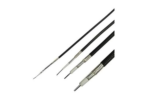
Different coaxial cable types affect RF performance including attenuation, flexibility, shielding, and frequency capability. TEJIATE provides RG series cables, low loss coaxial cables, and customized RF cable assemblies for various applications.
Two assemblies can use the same connector name and still be different parts.
SMA is a good example. An SMA cable assembly may use a straight plug, right-angle plug, bulkhead jack, reverse-polarity interface, crimp termination, solder termination, or a rear body sized for a specific cable diameter. A plug made for RG316 should not be casually substituted for a plug made for RG58. The front interface may look familiar, but the rear hardware, ferrule, pin, dielectric support, and crimp area are not the same.
The connector must match the equipment port first. Then it must match the cable.
SMA is common for compact RF modules, antennas, test leads, Wi-Fi, GPS, and many 50 ohm systems. BNC is still common in lab instruments and lower-frequency test equipment. N Type is used where a larger, more rugged interface is acceptable, often in antenna paths or higher-power systems. TNC gives threaded mating where vibration resistance is useful. MMCX and U.FL are used where the PCB or device space is tight.
None of these should be selected only by appearance.
Select SMA, BNC, N Type, TNC, or Other RF Interfaces by Equipment Port
The port decides the interface. The application decides the margin.
If the device has an SMA female jack, the cable side usually needs an SMA male plug. If the enclosure needs an external antenna port, a bulkhead connector may be better than a loose cable-end connector. If the assembly is repeatedly connected and disconnected in a lab, the buyer may need a more durable connector body, better strain relief, or a defined mating-cycle expectation.
For production, the connector drawing matters. A small difference in nut size, panel thread, gasket position, or rear crimp structure can affect installation. This is especially true for enclosure pigtails, where the outside interface must fit the panel and the inside cable must route without forcing a sharp bend.
Match Connector Gender, Polarity, and Mounting Style
Gender mistakes are still common in RF sourcing.
The safest method is to confirm the center contact. Male has a center pin. Female has a center socket. Thread direction and outer shell appearance can mislead buyers who are not used to RF naming.
Polarity also needs attention. Standard SMA and RP-SMA are not interchangeable, even when the outer coupling looks similar. A Wi-Fi antenna project may use RP-SMA, while a test instrument may use standard SMA. Ordering the wrong polarity can produce a part that looks close in photos but cannot mate correctly.
Mounting style is the third check. Cable end, bulkhead, flange, PCB mount, and panel mount versions solve different installation problems. For an RF cable assembly, the buyer should define not only the connector interface, but also how the connector will be fixed in the system.
| Connector Selection Field | Common Options | Selection Note |
| Connector A | SMA / BNC / N / TNC / MMCX / U.FL | Match the first device port |
| Connector B | Same or different RF connector | Match the opposite equipment |
| Gender | Male / Female | Confirm by center contact |
| Polarity | Standard / reverse polarity | Check mating part and drawing |
| Mounting Style | Cable end / bulkhead / panel mount | Match installation method |
| Adapter Needed | Yes / No | Prefer direct assembly for long-term use |
A direct cable assembly is not always cheaper than using a cable plus adapters. But it is usually easier to control. Fewer interfaces mean fewer points for mismatch, loosening, wrong mating, and shipment damage.
How Should Cable Type Be Chosen for Frequency, Loss, and Routing?
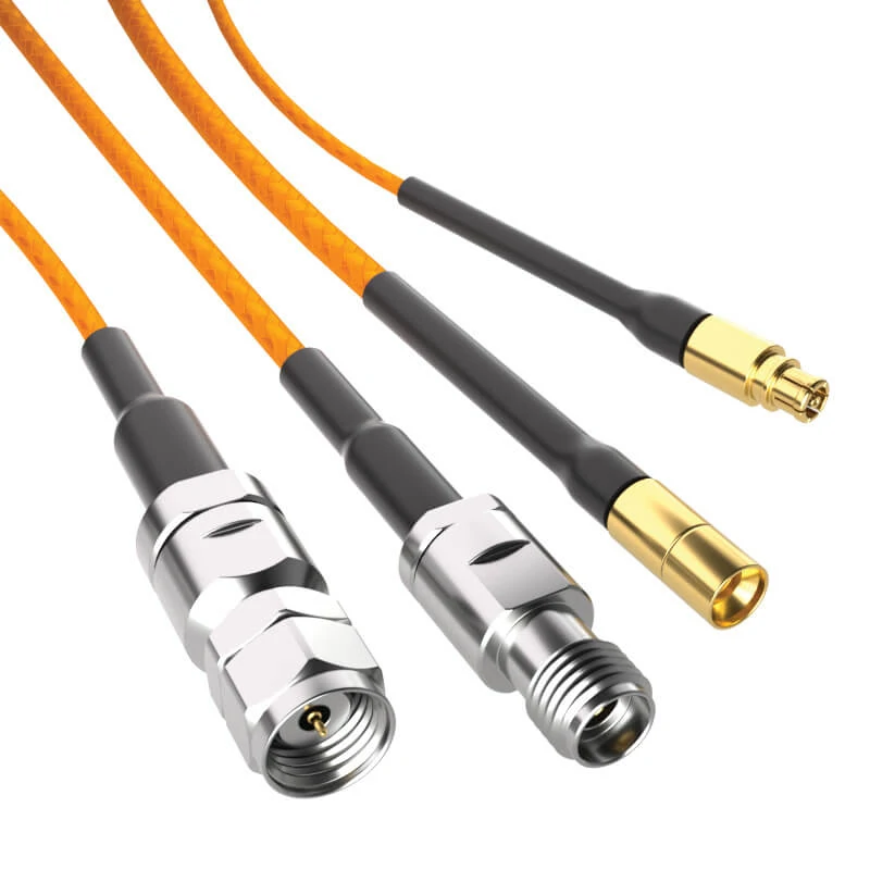
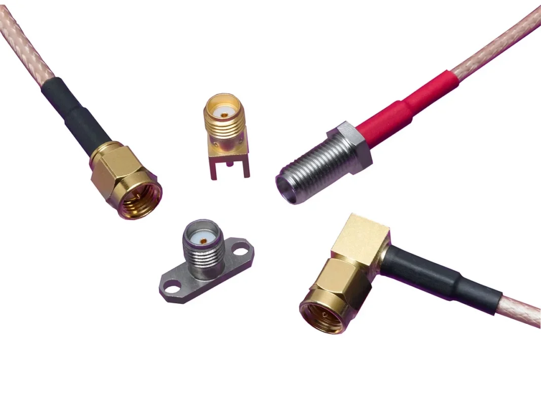
This RF cable assembly image shows multiple connector configurations including SMA and N type interfaces. TEJIATE provides custom RF cable assemblies with different coaxial cables, connector types, lengths, and frequency requirements for communication systems, RF testing, and electronic applications.
The cable usually becomes the limit before the connector name does.
That is easy to miss in purchasing. Buyers often start with the visible interface: SMA, BNC, N Type, TNC, MMCX, or U.FL. The cable is treated as a secondary detail. In a real RF cable assembly, it is not secondary. Cable diameter, dielectric material, shielding structure, braid contact, jacket stiffness, and bend behavior all affect the finished RF path.
A short RG316 jumper may work well inside a Wi-Fi module or GPS device. The same cable may not be the right choice for a longer antenna run at a higher frequency. Nothing looks wrong from the outside. The problem appears only when the cable loss, routing stress, and connector termination are tested together.
Before choosing cable type, confirm three things: highest operating frequency, finished cable length, and available routing space. If the cable must turn sharply behind a panel, a smaller flexible coax may be needed. If the assembly runs several meters to an antenna, low-loss cable may be safer. If the cable is part of a measurement setup, repeatability may matter more than flexibility.
Choose Flexible Coax for Short Internal RF Links
Flexible coax is usually selected for short device-to-device links, enclosure pigtails, wireless modules, GPS receivers, Wi-Fi devices, and compact test connections.
RG316 is a common option because it is flexible, available with many RF connector types, and easier to route than larger coax. RG174 is also used for short general RF links, but it normally gives less high-frequency margin. Very small coax such as RG178, 1.13 mm, or 0.81 mm solves space problems in compact devices, but it needs careful handling during stripping, soldering, crimping, and final installation.
The mistake is treating small cable as only a cheaper cable. It is really a routing solution with loss and durability limits. Pulling force, repeated bending, poor heat control, and weak strain relief can damage the assembly before it ever reaches the final equipment.
Use Low-Loss Cable When Distance or Frequency Increases
Low-loss cable becomes more important when length increases or when the system works near a frequency where ordinary flexible cable starts consuming too much signal budget.
At 100 mm, cable loss may not drive the decision. At 1 m, 3 m, or longer, it becomes more visible. This is common in antenna feed cables, outdoor radio equipment, gateways, repeaters, RF enclosures, and systems where receiver sensitivity or transmitted power has little margin.
Larger low-loss cable has trade-offs. It needs more bend space, larger connector bodies, stronger strain relief, and more installation clearance. Inside a tight enclosure, it may push against the panel or nearby components. On an external port, the cable weight may stress the bulkhead connector. So the decision is not only electrical. It is also mechanical.
Select Semi-Rigid or Microwave Cable for Stable Test Paths
Semi-rigid and microwave cable assemblies are used when stable routing and repeatable measurements matter.
They are not chosen because they are convenient. Semi-rigid cable is harder to form, less forgiving during installation, and unsuitable for repeated flexing. Its advantage is stability after the route is fixed. That can be useful in microwave fixtures, RF modules, calibration setups, and controlled test paths.
Microwave cable assemblies may also need stricter connector control, torque control, VNA sweep records, and better packaging. A continuity test can confirm that the conductor path is not open or shorted, but it cannot confirm insertion loss, return loss, or VSWR across the operating band.
| Cable Option | Better For | Main Risk |
| RG316 | Flexible SMA jumpers, GPS, Wi-Fi modules, short pigtails | Higher loss over longer length |
| RG174 | Short general RF links, compact routing | Limited high-frequency margin |
| RG178 / 1.13 mm | Small wireless modules and tight PCB areas | Fragile handling and termination |
| RG58 | General 50 ohm RF links and lab cables | Larger size than mini coax |
| Low-loss coax | Longer antenna runs and outdoor RF links | Larger bend space and heavier connector load |
| Semi-rigid cable | Microwave fixtures and stable routing | Less flexible and harder to rework |
This table is only a first filter. The final selection still depends on connector type, cable length, shielding, frequency range, test target, and how the assembly will be mounted.
How Can You Estimate RF Cable Assembly Loss Before Production?
Loss estimation does not have to be perfect to be useful.
Before samples are built, the buyer can already check whether the requested length and cable family make sense. This prevents a common problem: the supplier builds exactly what was requested, then the buyer discovers that the cable itself is too lossy for the system.
This is not a replacement for testing. It is a sourcing screen.
For example, a 150 mm antenna pigtail at 2.4 GHz may be acceptable with flexible coax. A 3 m cable at the same frequency should be reviewed more carefully. At 5.8 GHz or higher, the cable choice becomes stricter again. The buyer should ask for attenuation data at the target frequency, not only at a low reference frequency.
Add Connector Pair Loss and Adapter Margin
The cable is not the only source of loss.
Connector termination quality matters. A wrong ferrule size, loose braid contact, overheated dielectric, weak solder joint, or poorly aligned center pin can create unstable readings. The connector may mate correctly and still perform poorly at RF.
Adapters also deserve attention. During prototyping, they are useful. In production, they add extra mating points, extra mismatch risk, and more inspection uncertainty. If the final system always needs SMA to BNC, SMA to N Type, or SMA to U.FL, a direct custom RF cable assembly is usually cleaner than a standard cable plus adapters.
| Loss Factor | What to Check | Practical Buying Note |
| Cable length | Finished length | Longer cable increases loss |
| Cable attenuation | Value at target frequency | Do not compare only low-frequency data |
| Connector pair | Interface and termination quality | Match connector body to exact cable type |
| Adapter count | Extra mated interfaces | Avoid adapter stacks in fixed production |
| Bend condition | Bend near connector rear body | Add routing margin if space is tight |
| Test method | Continuity or VNA sweep | Continuity does not prove RF performance |
A buyer does not need VNA data for every simple cable. But if the assembly is used near the upper frequency range, in a test path, or in a repeat production project, the RFQ should include test frequency and pass/fail expectations.
How Do You Choose Between Standard, Low-Loss, and Microwave Assemblies?
The assembly category should follow the job of the cable.
Standard RF cable assemblies are suitable for short device links, common wireless modules, simple lab connections, and applications where frequency and loss targets are not aggressive. These assemblies may need controlled termination, defined torque, VNA sweep records, and careful protection during shipment.
How Should Shielding, Jacket, and Bend Radius Be Evaluated?
A cable assembly can fail after installation even if it passed inspection on the bench.
The reason is usually mechanical. The cable is bent tighter than expected. The rear of the connector is pulled by enclosure routing. The jacket rubs against a metal edge. The assembly is placed near a power module or switching circuit without enough shielding margin.
Shielding should match the electrical environment. For simple internal links, standard braided shielding may be enough. For noisy equipment, outdoor antenna paths, or dense electronic enclosures, shielding quality becomes more important. The buyer should not only ask for “shielded cable.” The supplier needs to know the application, routing distance, and nearby interference sources.
Jacket choice is also practical. A cable inside a fixed device does not face the same risk as a cable used on a test bench, outdoor box, or moving equipment. Heat, abrasion, oil, repeated bending, and UV exposure can all affect the correct cable choice.
| Routing Risk | Low-Risk Condition | High-Risk Condition |
| Bend radius | Smooth bend with space | Sharp bend near connector |
| EMI exposure | Shielding matched to layout | Shielding not confirmed |
| Cable movement | Fixed routing | Repeated flexing |
| Heat area | Jacket rating confirmed | Jacket material unknown |
| Connector strain | Strain relief added | Cable pulls on connector |
| Enclosure space | Enough clearance | Cable compressed after assembly |
The bend near the connector is the area to watch. Many failures do not happen in the middle of the cable. They happen where the cable exits the connector body.
How Are RF Cable Assemblies Tested Before Shipment?
Continuity testing is the baseline, not the full answer.
It confirms that the center conductor is connected, the shield path is connected, and there is no obvious short circuit. That is necessary for every RF cable assembly. But continuity does not prove RF performance. A cable can pass continuity and still show poor return loss, unstable VSWR, or excessive insertion loss at the target frequency.
For ordinary short cables, visual inspection and continuity may be enough. For high frequency cable assembly projects, microwave cable assemblies, antenna feed lines, or repeat production orders, the buyer should define the RF test method before production.
A useful test request may look like this:
Continuity test for all pieces. VSWR and insertion loss test at 2.4 GHz and 5.8 GHz for sample approval. Record test data for production batch if required.
How Should RF Cable Assemblies Be Specified for Different Applications?
The buyer should specify cable length, frequency band, outdoor exposure, waterproofing needs, and mounting method. Low loss RF cable may be useful, but only if there is enough space for the larger cable and connector body.
For enclosure pigtails, the panel side and internal side must both be clear. A common example is SMA female bulkhead outside the box with U.FL, MMCX, or SMA inside. In this case, nut size, gasket position, panel thickness, and bend direction may be just as important as the connector name.
For OEM production, add drawing version, label format, batch inspection, packaging method, and approved sample reference. Repeat orders become easier when the original assembly is described in full, not only by a short product nickname.
How Do You Compare RF Cable Assembly Suppliers?
Do not compare suppliers only by unit price.
A lower price may be fine for a simple cable. It becomes risky when the project needs mixed connectors, custom length, stable batch quality, inspection records, or controlled packaging. The supplier must understand both the connector side and the cable processing side.
Ask whether the supplier can support the exact cable type, connector body, ferrule size, polarity, panel style, and test requirement. Also ask how they handle repeat orders. A good sample does not help much if the second batch uses a different cable, different connector rear body, or different assembly method without notice.
| Evaluation Field | Why It Matters |
| Connector options | Supports SMA, BNC, N Type, TNC, MMCX, U.FL, or required interface |
| Cable options | Supports flexible, low-loss, and semi-rigid cable choices |
| Custom length | Reduces routing waste and installation stress |
| RF testing | Confirms VSWR or insertion loss when required |
| Drawing support | Prevents wrong gender, polarity, or panel dimension |
| Batch consistency | Important for OEM repeat orders |
| Packaging control | Protects connector threads, pins, and small interfaces |
Supplier capability is not only about having parts in stock. It is about building the same RF path repeatedly.
How Do You Send a Complete RF Cable Assembly RFQ?
A complete RFQ can be short if the fields are clear.
Use this format before asking for quotation:
| RFQ Field | Example |
| Connector A | SMA male straight |
| Connector B | BNC female bulkhead |
| Cable type | RG316 / RG58 / low-loss coax |
| Length | 100 mm / 300 mm / 1 m |
| Impedance | 50 ohm / 75 ohm |
| Frequency range | DC–3 GHz / DC–6 GHz / higher |
| Loss target | dB limit if required |
| Test requirement | Continuity / VSWR / insertion loss / return loss |
| Application | Antenna / module / test fixture / enclosure |
| Quantity | Sample or production batch |
| Drawing or photo | Required for replacement projects |
FAQ
How do I specify an RF cable assembly correctly?
Use a port-to-port description. Include connector A, connector B, cable type, length, impedance, frequency range, test requirement, application, and quantity. Add photos or drawings if the project is a replacement or has panel-mount details.
Is an RF cable assembly the same as a coax cable assembly?
They are closely related. A coax cable assembly describes the physical cable and connectors. An RF cable assembly places more attention on frequency, impedance, insertion loss, VSWR, shielding, and RF test requirements.
When should I choose a custom RF cable assembly?
Choose custom assembly when standard length, connector gender, polarity, mounting style, cable type, or test requirement does not match the equipment. It is also useful when adapter stacks should be removed from a production design.
Does a longer RF cable assembly always cause more signal loss?
Yes, cable loss generally increases as length increases. Frequency also matters. A cable that is acceptable at a short length may become unsuitable when the same cable is extended or used at a higher band.
What tests should be requested for RF cable assemblies?
Continuity is the basic test. For RF-sensitive systems, request VSWR, insertion loss, return loss, and test frequency records. The test should match the actual operating band, not only a convenient low-frequency check.
Can RF cable assemblies use different connectors on each end?
Yes. A cable assembly can use SMA on one end and BNC, N Type, TNC, MMCX, U.FL, or another RF connector on the other end. Confirm gender, polarity, impedance, and cable compatibility before ordering.
Final Buying Guidance
The safest RF cable assembly order is not the one with the longest description. It is the one with fewer guesses.
Before ordering, confirm the two equipment ports, cable type, length, impedance, operating frequency, routing space, and test requirement. If the assembly will be used near the upper frequency range, in an antenna path, or in a repeat production project, include loss target and inspection rules early.
A supplier can build what is requested. The buyer’s job is to make sure the request describes the actual RF path.
