
A test cable can look correct, mate correctly, and still create a measurement problem.
This happens often when a BNC interface is connected to another RF standard without checking the details behind the connector. The mechanical fit may be acceptable, but impedance, frequency range, and interface design can affect the final RF result.
A typical example is a laboratory engineer connecting a signal generator with an SMA output to an oscilloscope or test fixture using a BNC input. The adapter appears simple: one side is SMA, the other side is BNC. However, the actual RF path now includes another transition point. If the impedance, frequency rating, or adapter construction does not match the system, the measurement may show unexpected VSWR, insertion loss, or signal distortion.
This is where a properly selected BNC adapter becomes more than a mechanical connector change. It is an RF interface transition component that helps different equipment standards work together while maintaining the required electrical characteristics.
For engineers and procurement teams, the key is not only asking “does the connector fit?” The better question is “does this adapter match the complete RF path?”
How Do BNC Adapters Enable Flexible RF Interface Connections?
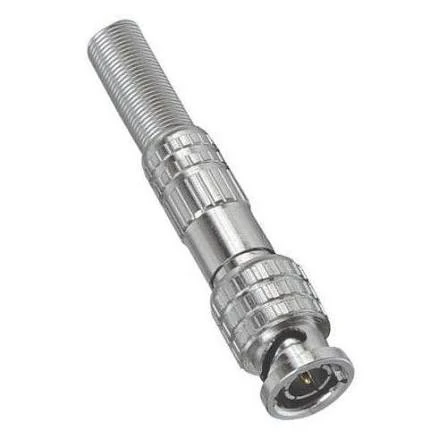
A BNC adapter provides a reliable RF interface transition between different connector standards. It is commonly used for connecting test equipment, coaxial cables, signal generators, and communication systems while maintaining proper mechanical and electrical compatibility.
In RF systems, different equipment platforms often use different connector standards.
A spectrum analyzer may use a BNC interface. A compact RF module may use SMA. An antenna system may use N-type.
A BNC adapter provides a direct mechanical and electrical transition between connector interfaces. It is commonly used in:
- RF test equipment
- signal generators
- oscilloscopes
- frequency counters
- communication equipment
- antenna test systems
- coaxial cable assemblies
The main purpose is not simply extending a cable. It is solving an interface mismatch problem.
This approach is especially useful during:
- prototype development
- laboratory testing
- equipment upgrades
- temporary measurement setups
- production debugging
However, every additional adapter introduces another RF transition. At lower frequencies this may have limited impact, but as frequency increases, the connector geometry and internal structure become more important.
Understand why adapters and connectors are not the same component
A common purchasing mistake is treating an RF connector and an RF adapter as identical parts.
A connector is normally part of a cable assembly, PCB, or equipment interface. It provides the original connection point.
An adapter works as a bridge between two existing interfaces.
| Component | Main Function | Typical Application |
| RF Connector | Creates the primary interface | Cable, PCB, equipment port |
| BNC Adapter | Converts one interface to another | Test equipment connection |
| Coax Adapter | Provides coaxial interface transition | Cable system integration |
| RF Adapter | General RF interface conversion | Communication and measurement systems |
For example, an SMA connector installed on an RF cable cannot directly connect to a BNC port. A suitable SMA-to-BNC adapter is required.
The adapter selection should consider:
- connector interface
- male/female configuration
- impedance
- operating frequency
- cable environment
- required measurement accuracy
A visually similar adapter may not always be interchangeable.
Compare BNC Adapters With General Coax Adapters
The terms BNC adapter, coax adapter, and RF adapter are sometimes used interchangeably during sourcing, but they describe different levels of application.
A BNC adapter specifically focuses on systems using BNC interfaces.
This type of description reduces incorrect substitutions during purchasing.
How Do BNC Male and Female Adapters Affect System Compatibility?
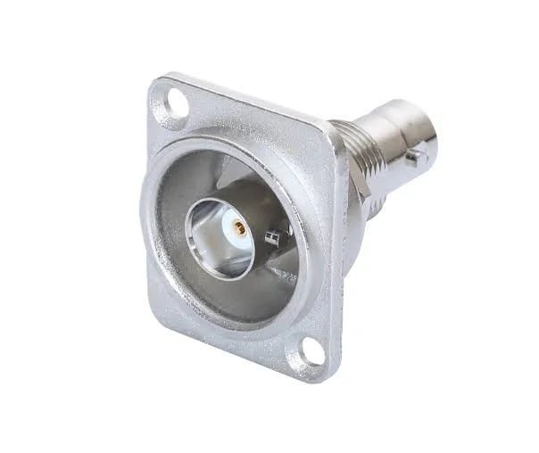
Different BNC adapter genders determine how RF components connect together. BNC male and female adapters are selected according to equipment ports, cable connectors, and system connection requirements.
A BNC adapter is often ordered after someone notices a simple problem: the cable is available, the instrument is available, but the two connectors do not match.
From a supplier’s perspective, this information is not enough.
The BNC interface itself has several variations. The connection direction, mating side, impedance, and application frequency all affect whether the adapter is suitable.
A wrong gender selection is one of the easiest mistakes to avoid, but it still happens frequently in sample ordering.
For example, an engineer may have a test cable with a BNC male plug and need to connect it to another BNC male interface. A standard BNC male-to-male connection will not solve the problem because both sides are plugs. The required solution may be a BNC female-to-female adapter or a different cable configuration.
The connector may look correct in a catalog image, but the actual mating condition determines whether the assembly works.
When Should Engineers Choose BNC Male or BNC Female Adapters?
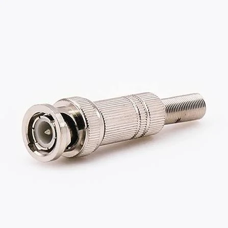
A BNC panel mount adapter is designed for equipment integration and fixed RF interface installation. It is widely used in communication devices, test systems, and custom electronic assemblies requiring stable coaxial connections.
The easiest way to understand BNC gender selection is to look at the receiving side.
A BNC male interface contains the center contact pin and locking structure.
A BNC female interface receives the male pin.
The selection depends on what needs to be connected.
| Adapter Interface | Connection Situation | Example |
| BNC Male | Connects into BNC female equipment port | Test instrument connection |
| BNC Female | Receives BNC male cable plug | Cable extension |
| BNC Male to Female | Changes connection direction | Temporary test setup |
| Custom BNC Adapter | Special interface combination | OEM equipment integration |
For standard laboratory work, gender mistakes are usually discovered quickly because the connector simply cannot mate.
The bigger problem appears in custom assemblies.
A cable assembly may already be produced with hundreds of connectors installed. If the adapter specification was incorrect at the beginning, the issue may not be discovered until system integration.
For this reason, procurement documents should include the complete interface description.
The second description leaves room for different interpretations.
How Do SMA to BNC Adapters Solve Equipment Interface Differences?
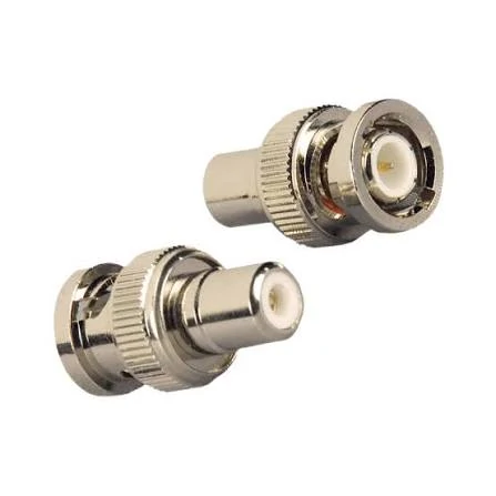
BNC coaxial adapters provide signal transitions between different RF interfaces. They are commonly applied in laboratory testing, cable assemblies, and electronic equipment connections where connector compatibility is required.
Many RF engineers encounter this situation during testing:
The device under test uses SMA.
The available laboratory equipment uses BNC.
The cable in stock uses another connector.
The problem is not the RF signal itself. The problem is interface compatibility.
This is where SMA-to-BNC adapters are commonly used.
They allow equipment with different connector standards to be connected without redesigning the complete cable system.
Every transition adds another interface point.
For low-frequency measurements, this may not create a noticeable issue.
For higher-frequency systems, engineers usually pay more attention to:
- connector machining accuracy
- contact alignment
- impedance consistency
- VSWR
- insertion loss
Match SMA and BNC Interfaces Before Building the RF Path
SMA and BNC serve different design purposes.
SMA is commonly selected for compact RF modules and higher-frequency applications.
BNC is widely used in laboratory instruments because of its convenient locking method.
When converting between them, the important point is not only the connector name.
The complete connection should be checked:
| Conversion | Application Example | Check Point |
| SMA to BNC | RF module to test instrument | Gender and impedance |
| BNC to SMA | Laboratory cable to RF device | Frequency range |
| BNC to BNC | Test cable extension | Cable compatibility |
| SMA to SMA | RF module connection | Interface specification |
A common field situation is using an adapter stack.
For example:
Equipment → BNC adapter → SMA adapter → cable assembly
The system may work mechanically, but each additional transition increases the number of possible mismatch points.
For measurement applications, reducing unnecessary adapters is usually preferred.
Why Should Engineers Confirm 50Ω or 75Ω Before Ordering BNC Adapters?
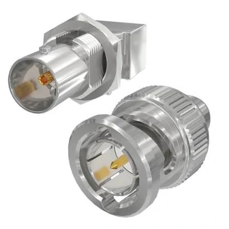
A BNC female panel mount adapter offers a fixed connection interface for RF equipment and coaxial systems. The design supports secure installation and reliable signal transmission in various electronic applications.
BNC is available in both 50Ω and 75Ω versions.
This is one of the most important details during selection because the two versions are used in different systems.
A visual check is not always enough.
The connector body may appear almost identical, but the electrical design is different.
50Ω BNC adapters are commonly found in:
- RF test systems
- communication equipment
- signal measurement applications
75Ω BNC adapters are more common in:
- video systems
- broadcast equipment
- cable television applications
Avoid Impedance Problems in RF Measurement Systems
When different impedance sections are connected together, signal reflection can occur.
In practical RF testing, engineers usually observe this through parameters such as:
- VSWR
- return loss
- measurement repeatability
A mismatch does not always mean the system immediately fails.
The actual impact depends on:
- operating frequency
- signal level
- cable length
- test accuracy requirement
For a simple monitoring connection, the effect may be acceptable.
For calibration, characterization, or product verification, impedance matching becomes much more important.
BNC Impedance Selection Guide
| Impedance | Typical Use | Selection Note |
| 50Ω | RF testing and communication systems | Match with 50Ω cables and equipment |
| 75Ω | Video and broadcast systems | Used mainly for video signal paths |
| Custom | Special applications | Confirm requirements before production |
A good purchasing habit is to include impedance in the first inquiry instead of confirming it after samples arrive.
BNC Adapter Selection Problems Usually Appear During Testing
Many BNC adapter issues are not found when the part arrives.
They appear later.
The adapter is installed, the equipment powers on, and the first measurement looks normal. Because everything works, the adapter is usually forgotten.
A few weeks later, another engineer uses the same test setup. The result is slightly different.
The first reaction is usually to check the instrument.
Then the cable.
Then the software.
The small transition piece between two connectors is often checked last.
This happens because an adapter feels like a passive mechanical part. In RF systems, that assumption can create problems.
A BNC adapter changes the physical connection between two interfaces. The internal contact structure, impedance design, and manufacturing tolerance all become part of the transmission path.
For simple connections, this may not create a visible issue.
For measurement systems, repeated testing, or higher-frequency applications, small differences can become noticeable.
Inspect the Adapter Before It Enters the Test Room
Incoming inspection for RF adapters does not need to be complicated.
The important thing is knowing what needs to be checked.
A production engineer normally starts with the physical condition.
The first questions are practical:
- Is this the ordered connector combination?
- Does the BNC locking mechanism work smoothly?
- Does the mating connector have abnormal looseness?
- Is the contact area clean?
These checks sound basic, but they prevent many unnecessary problems.
A wrong adapter can easily enter a project when several similar parts are stored together.
For example, a laboratory may have:
- 50Ω BNC adapters for RF testing
- 75Ω BNC adapters for video equipment
- different BNC-to-SMA conversion models
They may look almost identical inside a storage cabinet.
Without clear labeling, replacing one with another is easy.
Inspection Items Used for BNC Adapter Approval
| Item | Engineering Check |
| Interface | Confirm BNC and opposite connector |
| Gender | Check mating direction |
| Impedance | Match equipment and cable |
| Frequency | Confirm working band |
| Mechanical | Verify locking and contact |
| Electrical | Test when required |
For a general laboratory connection, visual inspection and continuity testing may be enough.
For calibration fixtures or repeat measurement systems, additional RF testing is usually considered.
A continuity meter can confirm that the conductor is connected.
It cannot tell whether the RF transition will perform correctly.
The Information Missing From Many BNC Adapter Requests
From the supplier side, many RF adapter inquiries start with incomplete information.
The quantity is clear.
The product is not.
Without these details, two suppliers may quote completely different products.
This sentence already tells the supplier the basic structure.
What Engineers Usually Put Into a BNC Adapter Specification
| Specification | Example |
| Adapter Type | BNC to SMA |
| Interface | BNC female / SMA male |
| Impedance | 50Ω |
| Application | RF test equipment |
| Frequency | Required operating range |
| Quantity | Prototype or production |
For custom projects, the information may go further.
Some customers also provide:
- mounting requirement
- environmental condition
- cable type
- required plating
- packaging method
This information is useful because the adapter is rarely purchased alone.
It normally belongs to a larger assembly:
equipment + cable + adapter + test requirement.
Why Similar-Looking BNC Adapters Are Not Always Replaceable
One of the easiest mistakes in RF purchasing is replacement by appearance.
A technician sees a BNC adapter with the same outside shape and assumes it can replace the original.
This works in some situations.
It also creates problems in others.
The difference may come from:
- impedance design
- internal dimensions
- contact material
- frequency capability
The issue may not appear immediately.
The adapter may pass a basic connection check but behave differently during RF measurement.
Another situation appears when too many adapters are combined.
For example:
Test instrument
→ BNC adapter
→ SMA adapter
→ cable assembly
The system can still operate.
However, every additional connection introduces another mechanical and electrical transition.
For critical measurements, engineers usually try to reduce unnecessary conversion points.
Practical Notes for Purchasing Teams
A BNC adapter is inexpensive compared with most RF instruments.
However, choosing the wrong part can create much higher costs:
- repeated testing
- engineering investigation
- delayed validation
- replacement shipments
A simple specification sheet can avoid most of these problems.
Before ordering, confirm:
- connector combination
- gender
- impedance
- frequency range
- application
- inspection requirement
This information is usually enough for a supplier to recommend a suitable standard product or evaluate a custom design.
FAQ
Can 50Ω and 75Ω BNC adapters replace each other?
They may physically connect, but they are designed for different systems. The impedance requirement should be confirmed before replacement.
I have a BNC adapter that fits my equipment. Is there anything else I need to check?
A mechanical connection only confirms that two interfaces can mate together. Before using the adapter in an RF system, it is worth checking the impedance and working frequency. For example, a 50Ω BNC adapter and a 75Ω BNC adapter may look similar, but they are normally used in different signal environments.
Does a BNC adapter only solve a connector mismatch?
Not exactly. The first purpose is to connect two different interfaces, but the adapter also becomes part of the RF path. When the connection is used for testing, engineers normally pay attention to details such as impedance, frequency capability, and the quality of the transition.
What information helps suppliers select the correct BNC adapter?
The connector names are only the starting point. A supplier normally needs to know how the adapter will be connected, such as the two interface types, connector direction, electrical requirement, and intended use. Clear information at the quotation stage helps avoid selecting a part that only works mechanically.
