
The first sample passed the bench test. The problem appeared when the same setup was moved to another instrument.
One side used an N Type connection from an RF cable assembly. The other side was a BNC input on laboratory equipment. The engineer installed an adapter, checked continuity, and the signal was present. Nothing looked wrong.
The issue was not the connection itself.
At higher frequencies, a connector conversion involves more than changing the mechanical interface. The adapter becomes part of the RF path. Its impedance, frequency capability, connector condition, and contact quality can influence the measurement result.
This is why selecting an n type to bnc adapter requires more information than simply confirming that an N connector can mate with a BNC port.
In practical RF work, this type of conversion appears frequently in antenna testing, communication equipment verification, prototype debugging, and laboratory measurement systems. Engineers often need to connect equipment from different manufacturers without replacing existing cables or modifying hardware.
The right adapter makes the conversion simple. The wrong one can introduce problems that are difficult to trace.
How Does an N Type to BNC Adapter Connect Different RF Environments?
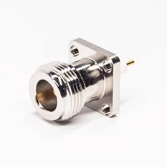
This N Type to BNC adapter is used for RF testing, laboratory equipment connection, and coaxial signal conversion applications. It helps connect N Type interfaces with BNC ports while maintaining stable RF transmission.
N Type and BNC connectors usually appear in different parts of an RF workflow.The bayonet locking mechanism allows technicians to connect and disconnect equipment quickly, which is useful when an oscilloscope, signal generator, or monitoring device is used for repeated measurements.
The two connector families are often connected when the system side and test side were designed with different requirements.
The adapter provides a practical transition without rebuilding the complete cable assembly.
This approach is common during:
- prototype evaluation;
- temporary laboratory setups;
- equipment maintenance;
- RF troubleshooting;
- incoming inspection.
However, the adapter should not be treated as an invisible component.
Once installed, it becomes another connection point in the RF chain.
Why Are N Type and BNC Interfaces Commonly Used Together?
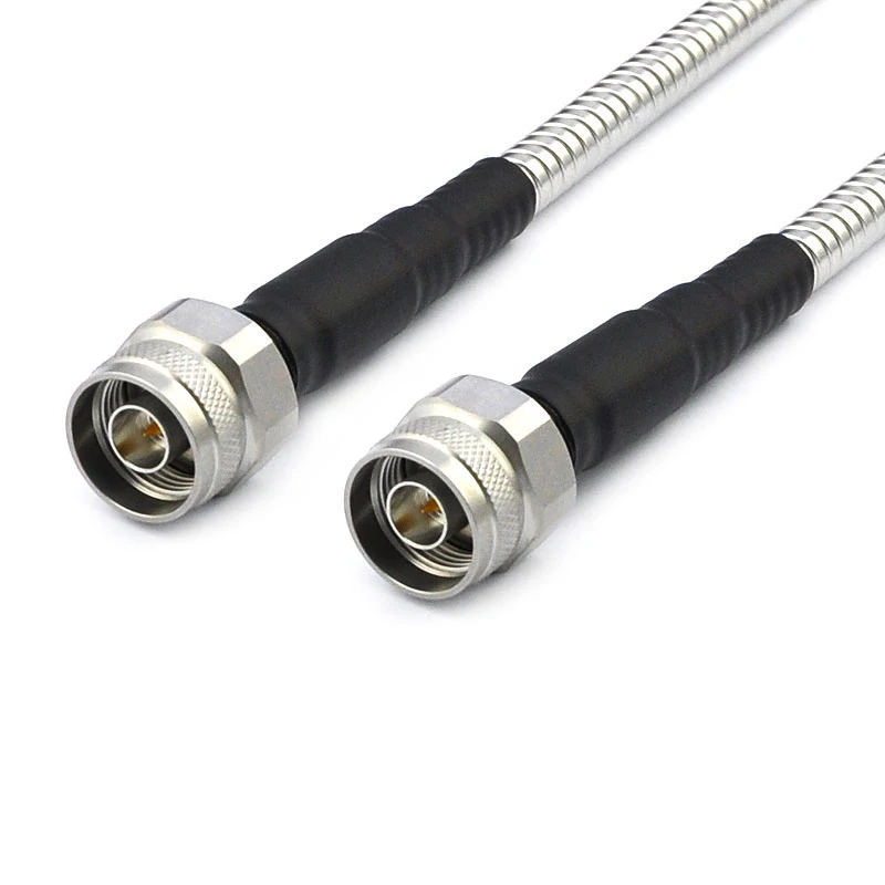
N Type coaxial cable assemblies provide stable signal transmission for antenna systems, wireless communication equipment, and RF testing applications. Connector selection should match impedance and frequency requirements.
The reason engineers search for n to bnc adapter solutions is usually not because they need a new RF cable. More often, they need to connect existing equipment.
A communication system may already use N Type cable ports because the installation requires a threaded connection. The available test equipment may only provide BNC ports because it was designed for fast laboratory access.
Replacing either side can be expensive or unnecessary.
A small adapter solves the physical mismatch.
A frequent purchasing mistake is describing the requirement only as “N BNC converter”.
This description does not define the actual part.
For RF sourcing, the request usually needs to include both interfaces:
- N Type side gender;
- BNC side gender;
- impedance;
- frequency requirement;
- application equipment.
For example:
N male to BNC female adapter, 50Ω, DC–6 GHz, used for RF measurement equipment.
This specification gives a supplier enough information to check compatibility before production.
How Do You Match the Adapter Direction Before Ordering?
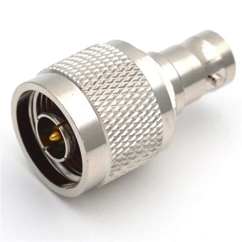
The terms n type to bnc adapter and bnc to n adapter often create confusion because they describe the same connector family conversion from different viewpoints.
The physical adapter is selected according to the two interfaces that need to be connected.
For example:
- An N Type cable needs to connect to a BNC instrument port.
- A BNC output needs to connect to an N Type cable assembly.
- An RF module has an N female connector and needs a BNC cable connection.
These situations may require different gender combinations.
Many sourcing errors happen because buyers check only the equipment model and ignore the actual cable termination.
N Type to BNC Adapter Direction Reference
| Connection Situation | Possible Adapter Requirement |
| N cable to BNC instrument | N to BNC adapter |
| BNC cable to N equipment | BNC to N adapter |
| N female port to BNC cable | Confirm N male side requirement |
| BNC female port to N cable | Confirm BNC male side requirement |
The connector names are simple. The actual selection depends on the complete RF path.
Why Physical Connection Does Not Guarantee RF Compatibility
A connector that fits mechanically can still be unsuitable electrically.
This is one of the most common misunderstandings in RF adapter selection.
An adapter mainly solves:
- interface conversion;
- mechanical connection;
- installation convenience.
It does not automatically solve:
- impedance mismatch;
- excessive insertion loss;
- unsuitable frequency range;
- poor contact condition.
For example, BNC connectors exist in both 50Ω RF versions and 75Ω versions used in video systems. They may look similar and physically connect, but the electrical characteristics are different.
In a low-frequency signal monitoring application, the difference may not be obvious.
In RF measurement, the effect can become visible through:
- increased VSWR;
- changed return loss;
- unstable measurement results.
For precision applications, engineers usually verify the complete setup rather than relying only on connector compatibility.
A VNA test can help evaluate parameters such as:
- insertion loss;
- return loss;
- VSWR.
The adapter is small, but its position in the signal path means it should be considered during system evaluation.
How Does 50Ω Matching Affect N Type to BNC Adapter Selection?
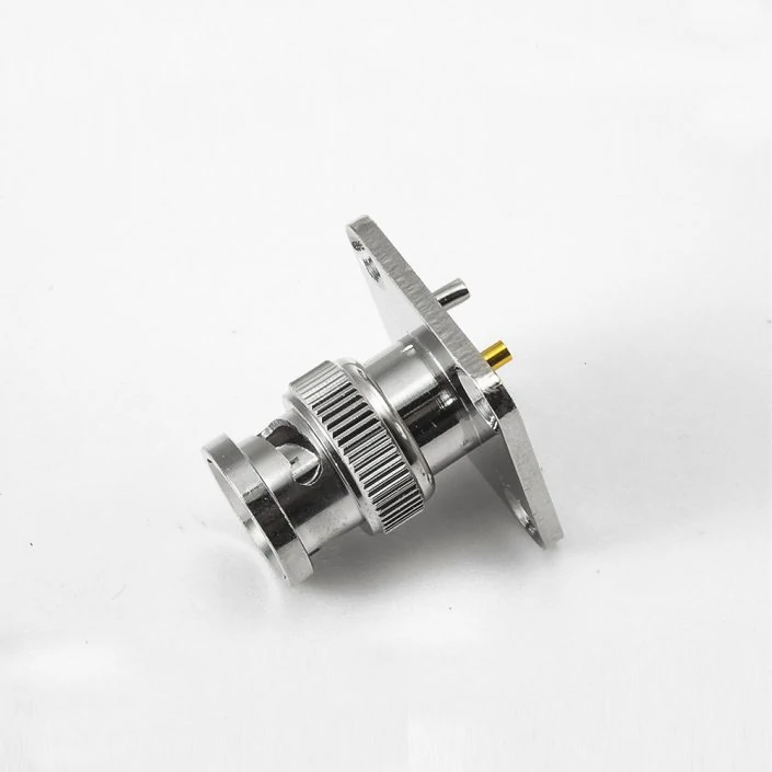
This N female to BNC male RF adapter allows connection between N Type equipment ports and BNC cables. Commonly used in RF testing, antenna systems, and signal measurement applications.
A connector mismatch may not be obvious during a basic signal check.
The equipment powers on, the waveform appears, and the connection seems normal. Problems often appear later when the system moves closer to the target frequency range or when measurement accuracy becomes important.
For most RF applications, the first specification to confirm is impedance.
An N Type to BNCadapter used in RF systems is normally based on a 50Ω signal path. This means the N Type connector, adapter, cable, and test equipment should maintain the same impedance environment.
A typical RF measurement path may look like:
The goal is not simply to make the connectors fit. The goal is to maintain a controlled RF path.
Keep Impedance Consistent Across the RF Signal Path
RF signals are sensitive to impedance changes because part of the signal energy can reflect back toward the source.
This reflection can affect:
- return loss;
- VSWR;
- measurement stability;
- signal transmission accuracy.
The adapter itself is only one part of the system.
A common mistake is checking the adapter specification while ignoring the cable and equipment connected on both sides.
Avoid Mixing RF BNC and 75Ω Video BNC Applications
BNC connectors are widely used, but not every BNC interface is designed for the same purpose.
The two common categories are:
50Ω BNC
Used for:
- RF testing;
- signal generators;
- measurement systems;
- communication equipment.
75Ω BNC
Used mainly for:
- video systems;
- broadcast applications;
- digital video transmission.
They may share the same basic locking structure, but their electrical characteristics are different.
This creates a practical sourcing issue.
A buyer may find a BNC adapter that physically connects to the instrument but does not match the intended RF system.
For low-frequency applications, the impact may be limited.
For RF measurement, especially near the upper operating range, the mismatch can influence test results.
Before selecting an rf test adapter, confirm:
- system impedance;
- operating frequency;
- equipment interface;
- cable specification.
How Does an N Type to BNC Adapter Affect RF Testing Accuracy?
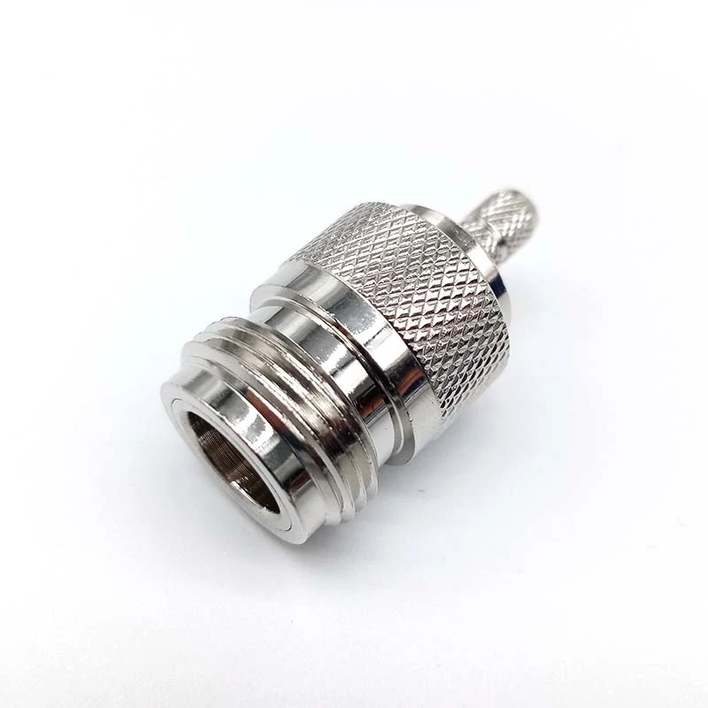
An RF coaxial adapter converting between N Type and BNC connector interfaces. Suitable for communication equipment, RF measurement systems, and laboratory applications requiring different connector standards.
A small adapter adds another connection point.
In simple laboratory monitoring, this may not create a noticeable issue. In precision measurement, every additional interface should be considered.
An adapter can influence:
- insertion loss;
- return loss;
- VSWR;
- calibration accuracy.
The actual impact depends on the adapter design, frequency range, manufacturing consistency, and connection condition.
A low-frequency adapter used below its rated range may perform normally.
The same adapter used near its upper frequency limit may require additional verification.
Evaluate Adapter Influence Before Precision Measurements
For applications involving a VNA or other RF analysis equipment, engineers normally check the complete setup rather than evaluating only individual components.
For example, a VNA test may evaluate:
| Parameter | Why It Matters |
| Return Loss | Shows reflected signal level |
| VSWR | Indicates impedance matching condition |
| Insertion Loss | Shows signal loss through the path |
| Phase Response | Important for some measurement systems |
The adapter may be small compared with the entire test setup, but it is still part of the measurement chain.
Reduce Adapter Stacking in RF Measurement Systems
Using one adapter is often practical.
Using several adapters together creates additional uncertainty.
The system may still operate, but each connection introduces another mechanical interface.
When Should You Use an N Type to BNC Adapter Instead of a Cable Assembly?
Typical applications:
- laboratory testing;
- prototype verification;
- troubleshooting;
- temporary equipment connection.
Advantages:
- quick installation;
- reusable;
- easy equipment conversion.
Cable assemblies are often preferred when the connection becomes part of a fixed system.
Typical applications:
- production equipment;
- outdoor RF installation;
- repeated testing stations;
- long-term deployment.
Advantages:
- fewer connection points;
- better mechanical stability;
- controlled cable length;
- easier documentation.
Protect Connectors When Connecting Large Coaxial Cables to BNC Equipment
One detail that is often overlooked is mechanical stress.
Some N Type cable assemblies use relatively large coaxial cables. When connected directly to smaller BNC equipment through an adapter, the cable weight may place stress on the BNC port.
Possible results include:
- loose connection;
- damaged instrument connector;
- unstable contact.
This is especially relevant in test environments where cables are frequently moved.
A practical solution may be:
- use a shorter adapter;
- provide cable support;
- select a suitable cable assembly;
- avoid hanging heavy cables directly from instrument ports.
The RF connection should be considered mechanically as well as electrically.
Adapter vs Cable Assembly Decision Reference
| Working Condition | Recommended Choice | Reason |
| Temporary RF test | N Type to BNC adapter | Fast conversion |
| Prototype development | Adapter | Flexible setup changes |
| Fixed production station | Cable assembly | Better repeatability |
| Outdoor installation | Cable assembly | Improved mechanical protection |
| Heavy coaxial cable connection | Cable assembly | Reduce connector stress |
How Do N Type to BNC Adapters Compare With Other RF Conversions?
An N Type to BNC adapter is usually selected because two pieces of equipment already exist.
In actual projects, engineers rarely start with “I need this adapter.” The requirement usually comes from a connection problem:
A cable assembly is already finished, but the new test instrument uses a different port.
A laboratory has several instruments from different suppliers.
A prototype needs temporary access for measurement.
In these situations, the adapter is not the main component. It is a connection bridge inside a larger RF setup.
That is also why different RF conversions should not be treated as interchangeable.
When Should You Consider N Type to SMA Conversion Instead?
N Type and SMA are both common RF interfaces, but they usually appear in different environments.
SMA is more common in compact RF assemblies where installation space is limited.
A simple comparison:
| Conversion | Common Use Case | Main Check Point |
| N Type to BNC | Laboratory equipment and RF instruments | BNC impedance and instrument input |
| N Type to SMA | RF modules and compact devices | SMA gender and frequency range |
| SMA to N Type | Test cables and antenna interfaces | Mechanical compatibility |
A common mistake is selecting based only on connector size.
A smaller connector does not automatically mean it is suitable for a higher-frequency application. The actual limit may come from the cable, termination method, or test requirement.
Why Are N Type to BNC and N Type to TNC Used Differently?
N Type, BNC, and TNC may all appear in coaxial systems, but their mechanical designs serve different purposes.
A simplified selection idea:
| Requirement | More Suitable Interface |
| Frequent test connection changes | BNC |
| Compact rugged RF equipment | TNC |
| Antenna and communication systems | N Type |
The final choice still depends on the complete assembly, including cable diameter, frequency range, and installation environment.
How Are N Type to BNC Adapters Used During RF Testing?
The most common use of an n type to bnc adapter is connecting equipment that was never designed to connect directly.
This happens often in development laboratories.
A communication module may use an N Type port because it connects to an antenna cable.
The available measurement equipment may only provide BNC input.
This approach is practical, especially during early development.
The important point is keeping the test condition documented.
What Should Be Recorded When Using an Adapter in a Test Setup?
A measurement result is only useful when the setup can be repeated.
For RF testing, the record should include:
| Item | Example Record |
| Adapter configuration | N male to BNC female |
| Impedance | 50Ω |
| Operating frequency | Target test band |
| Cable type | RG58 / RG142 / other coax cable |
| Equipment | Signal generator / VNA / analyzer |
| Calibration condition | Before measurement |
This information prevents a common problem:
The engineer repeats the test later but changes the adapter or cable without realizing the measurement condition is different.
Why Can the Same Adapter Work in One Test but Fail in Another?
RF results are affected by the whole connection path.
A setup may work during a basic signal check but show different behavior during precision measurement.
Possible reasons include:
- adapter frequency limitation;
- damaged connector contact;
- loose mating;
- cable mismatch;
- additional adapters in the path;
- calibration differences.
A continuity test only confirms that the conductor is connected.
It does not show:
- return loss;
- VSWR;
- insertion loss.
For applications where RF performance matters, the adapter should be included during system verification.
How Should Buyers Specify an N Type to BNC Adapter?
Many sourcing mistakes start with incomplete product descriptions.
A request like:
Need N BNC adapter
usually creates questions later.
A better specification is closer to:
N female to BNC male adapter, 50Ω, used for RF testing equipment, operating frequency up to required band.
The exact frequency should be based on the application.
A low-frequency monitoring connection and a VNA measurement connection should not use the same selection standard.
What Information Should Be Included in an RF Adapter Purchase Request?
For engineering samples, the following information is usually enough:
| Specification | Required Information |
| Interface A | N Type male/female |
| Interface B | BNC male/female |
| Impedance | 50Ω / 75Ω |
| Frequency | Operating frequency |
| Quantity | Sample or production quantity |
| Application | Test, antenna, equipment connection |
For production projects, buyers may also need:
- plating requirement;
- mechanical dimensions;
- environmental conditions;
- inspection standard;
- packaging method.
A clear specification reduces repeated confirmation between purchasing, engineering, and suppliers.
FAQ
Is an N Type to BNC adapter suitable for VNA testing?
It can be used, but the adapter should be considered part of the measurement path. Calibration and verification may be required when measurement accuracy is important.
Is an N Type to BNC adapter the same as a BNC to N adapter?
They describe the same connector conversion family, but the required configuration may be different. The actual adapter selection depends on which side uses the N Type interface, which side uses BNC, and whether the connectors are male or female. Checking only the conversion name can lead to ordering the wrong part.
What information should I send when requesting an N Type to BNC adapter?
A connector name alone is usually not enough for accurate selection. The supplier normally needs to know the N Type side, BNC side, male/female combination, impedance, frequency range, and intended application. For example, an adapter used for a laboratory RF test setup may require different specifications from one used only for basic signal monitoring.
I only need an N to BNC conversion. Why do I need to confirm impedance?
The connector shape does not define the complete RF performance. N Type systems are commonly used with 50Ω impedance, while BNC connectors can also be found in 75Ω applications.
What details should be included when asking for an N Type to BNC adapter quotation?
A supplier normally needs more than the connector names. The request should include the N Type interface, BNC interface, male/female combination, impedance, frequency range, quantity, and application. For RF testing projects, adding the instrument model or working frequency can help avoid selecting an unsuitable adapter.
