
An adapter can fit both connectors and still be the wrong part.
This happens frequently when an N-type antenna cable has to connect to a BNC-equipped spectrum analyzer, receiver, test panel, or older RF instrument. The buyer searches for an N to BNC adapter, selects a product that looks correct, and confirms continuity after delivery. The mechanical connection works, but the RF path may still contain the wrong gender, a 50-ohm-to-75-ohm mismatch, an inadequate frequency rating, or too much load on the equipment’s BNC port.
The product name alone is not enough. An N-to-BNC transition must be selected from the two existing equipment ports outward. After that, impedance, frequency, RF power, installation environment, cable weight, and acceptance testing all need to be checked.
Which Port Pair Requires an N to BNC Adapter?
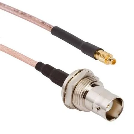
RF coaxial cable assembly featuring a panel-mount BNC female connector and a miniature snap-on connector. This configuration can provide a flexible transition between equipment interfaces while reducing direct mechanical load on the BNC port. Connector series, impedance, frequency, and mounting dimensions should be verified before ordering.
Start with the equipment, not the adapter listing.
Record the connector on Device A and the connector on Device B. For each port, confirm the connector family, gender, mounting style, and center contact. An antenna with an N female socket does not require an “N female adapter end.” It requires an N male end that can mate with that socket.
The same rule applies at the BNC side.
A BNC female instrument port needs a BNC male adapter end. A BNC male port needs a BNC female adapter end. Signal direction does not change this mating relationship.
Translate the existing ports into mating ends
Use the following selector before requesting a quotation.
| Existing N-Type Port | Existing BNC Port | Adapter Required |
| N female | BNC female | N male to BNC male |
| N female | BNC male | N male to BNC female |
| N male | BNC female | N female to BNC male |
| N male | BNC male | N female to BNC female |
| Either port unknown | Either port unknown | Inspect both interfaces before ordering |
This table avoids one of the most common RF purchasing errors: copying the equipment connector description directly into the adapter description.
For example, this equipment combination:
Antenna port: N female Instrument port: BNC female
requires:
N-type male to BNC male adapter
It does not require an N female to BNC female adapter.
Check the center contact and coupling body separately
Connector gender should be confirmed at the mating face. The center contact is important, but it should not be the only inspection point.
For N-type connectors, inspect the external or internal threaded coupling structure. For BNC connectors, inspect the bayonet sleeve and locking lugs. Product photographs can be misleading when they show only the side of the adapter.
A drawing is safer than a product title. It should show:
- N-type interface and gender
- BNC interface and gender
- Center pin or socket
- Overall length
- Coupling dimensions
- Body shape
- Mounting or bulkhead features, if present
Does “N to BNC” Mean Something Different From “BNC to N”?
For a normal passive adapter, search order does not define signal direction.
The phrases N to BNC adapter, BNC to N adapter, N type to BNC adapter, and BNC to N type adapter may all describe the same between-series product family. Buyers often start the description from the equipment they are looking at first.
An antenna technician may say:
N to BNC adapter
A laboratory user looking at the instrument may call the same interface pair:
BNC to N adapter
The actual part is still determined by the two connector ends.
A receive signal can travel from an N-type antenna toward a BNC receiver. A signal generator output can travel from a BNC instrument toward an N-type test fixture. The adapter name does not change when the RF direction is reversed.
For purchase orders, normalize the wording:
N-Type Male to BNC Male Adapter 50 Ohm Straight Required Frequency: DC to 3 GHz
Avoid descriptions such as:
N-BNC connector N/BNC conversion head BNC antenna adapter
Those descriptions leave the supplier to guess gender, impedance, frequency range, and mechanical form.
Can Both Interfaces Share the Same 50-Ohm RF Path?
Not automatically.
N-type connectors used in wireless, antenna, communication, and RF test systems are commonly 50 ohms. BNC connectors, however, are available in both 50-ohm and 75-ohm versions. The two BNC variants may look similar enough to be confused during sourcing.
A passive adapter changes the connector family. It does not act as a 50-to-75-ohm transformer.
Before approval, check the nominal impedance of:
- The N-type equipment port
- The BNC equipment port
- The adapter
- Every connected coaxial cable
- The antenna, load, terminator, or test fixture
The 50-ohm coaxial cable selection guide provides additional background for keeping the cable and connector path at the same nominal impedance.
Estimate a 50-to-75-ohm mismatch
For an ideal transition, reflection coefficient can be estimated as:
This value is an early screening calculation, not a guaranteed measurement result. Actual performance also depends on frequency, cable length, connector geometry, assembly quality, and the rest of the load.
A 50-ohm N port and a 75-ohm BNC video input may physically connect, but physical compatibility is not electrical matching. If the application needs controlled impedance conversion, specify a matching network, transformer, attenuation pad, or purpose-designed interface rather than a basic adapter.
How Much Mechanical Load Will the BNC Port Carry?
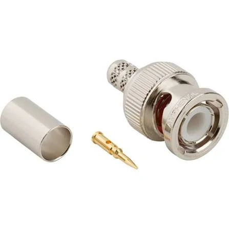
Exploded view of a BNC male crimp connector, including the connector body, gold-plated center contact, and crimp ferrule. The interface gender, center contact, cable compatibility, and impedance should be verified when selecting a BNC cable or N to BNC adapter system.
This question is often ignored until an instrument connector becomes loose.
An N-type connector is physically larger than a BNC connector. The N side may also be attached to a thick, stiff cable such as RG213, LMR-type feeder cable, or another low-loss antenna cable. When that cable hangs horizontally from a rigid adapter, its weight creates leverage at the BNC panel.
The approximate bending moment can be screened with:
Doubling the unsupported distance approximately doubles the bending moment for the same load. That makes adapter length relevant even when two products have similar RF specifications.
Risk rises when the installation includes:
- A long rigid adapter body
- A heavy or stiff N-type cable
- Horizontal cable routing
- Repeated equipment movement
- Vibration
- A thin instrument panel
- A recessed or poorly supported BNC connector
- Side pulling during installation
BNC port load risk score
The following score is a practical project-screening tool rather than an industry standard.
Rate each factor from 1 to 5:
Port Load Risk =Adapter Length+ Cable Weight+ Cable Stiffness+ Side Pull+ Vibration+ Panel Weakness
Interpret the result as follows:
- 6–10: A rigid adapter may be acceptable for a supported bench connection.
- 11–18: Add cable support and validate the equipment port.
- 19–30: Use a short flexible BNC-to-N cable assembly or another strain-relieved transition.
The score does not replace mechanical testing. Its purpose is to stop buyers from treating every adapter as a zero-load component.
Where Does a Rigid Adapter Fit Better Than a Jumper?
A rigid N-to-BNC adapter works well when both ports are aligned, the connection is short, and no heavy cable is pulling on the assembly.
Typical uses include:
- Temporary laboratory connections
- Antenna analyzer setups
- Short receiver tests
- Closely positioned RF panels
- Low-movement indoor systems
- Connections with supported cables
A rigid adapter is compact and removes the need for an extra cable assembly. It can also simplify calibration when the adapter is the only transition between two reference planes.
The problem starts when installation geometry is not straight.
A short jumper is usually safer when:
- The ports are offset
- The N cable approaches from the side
- The instrument moves during use
- The cable is thick or stiff
- Nearby connectors need clearance
- Vibration is present
- The transition is permanently installed
- Outdoor sealing must be placed away from the instrument
The jumper adds cable length and two cable terminations, so it is not electrically free. Still, a properly specified cable assembly may provide a more stable system than a rigid adapter that places continuous stress on the BNC connector.
The SMA vs BNC vs N-Type comparison explains why these connector families are normally assigned different mechanical roles.
How Should Frequency and Power Limits Be Checked?
Use the lowest-rated part as the system ceiling.
The complete path may contain:
N-type equipment port→ N-to-BNC adapter→ BNC cable→ BNC instrument port
The N-type interface may have a higher frequency capability than the BNC side, but that does not increase the rating of the complete assembly. The adapter’s internal transition can also become the limiting section.
Ask for the adapter’s documented frequency range rather than using a general connector-family rating.
Also specify:
- Maximum VSWR across the required band
- Minimum return loss
- Maximum insertion loss
- Test frequency points or sweep range
- Maximum average RF power
- Peak voltage, where relevant
- Ambient temperature during use
- Connected cable type
- Measurement reference planes
Frequency rating and measurement accuracy are not the same thing. A part may remain mechanically usable at a stated upper frequency while producing more reflection or insertion loss than the project permits.
Power handling also depends on frequency, impedance, temperature, contact condition, and connector cleanliness. A product advertised simply as “high power” should not be approved without test conditions.
For manufacturer configuration examples, Amphenol RF publishes an official range of N-Type to BNC adapters. Use the specific product drawing and data rather than assuming every configuration shares the same operating limit.
Which Antenna and Test Setups Benefit From This Transition?
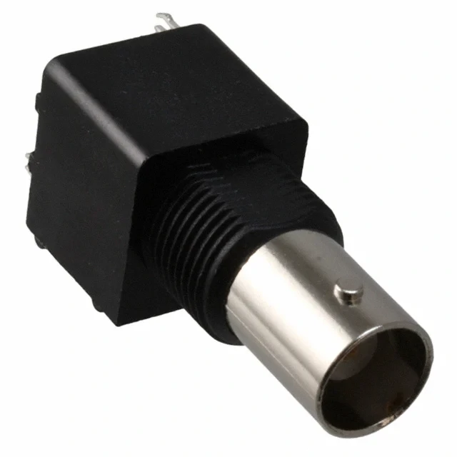
BNC female connector with a black insulated PCB-mount housing for installation in RF equipment and electronic test systems. Confirm the mating gender, impedance, mounting dimensions, and frequency range before connecting an N to BNC adapter.
The most common use is connecting N-type antenna hardware to BNC test equipment.
Examples include:
- Spectrum analyzers
- Antenna analyzers
- Frequency counters
- Signal generators
- RF receivers
- Monitoring equipment
- Test chambers
- Industrial RF panels
- Legacy laboratory instruments
Keysight’s 11854A accessory kit is an official example of using 50-ohm N-to-BNC interface combinations in network analyzer measurement configurations. The kit includes several gender combinations because test setups do not all use the same equipment ports.
That is a useful sourcing lesson: “N to BNC” is a product family, not a complete part number.
The RF adapter guide gives broader guidance on between-series adapters and the effects of adding transitions to an RF path.
Review outdoor applications separately
An N-type connector is often selected for outdoor antenna infrastructure because its threaded coupling is firm and weather-resistant versions are available. The presence of an N interface, however, does not make the complete adapter waterproof.
For outdoor use, verify:
- IP rating of the complete connection
- Connector orientation
- Water drainage path
- Sealing boot compatibility
- Self-amalgamating tape requirements
- Cable support
- Corrosion-resistant plating
- Temperature range
- UV exposure
- Condensation inside the enclosure
A standard indoor BNC interface should not be exposed simply because the adapter’s N side is attached to an outdoor feeder.
How Can Adapter Chains Be Removed From the Signal Path?
Adapter chains usually appear gradually.
A laboratory may already have a BNC-to-SMA adapter. Another project adds an SMA coupler. The antenna cable uses N-type, so an SMA-to-N adapter is installed at the end.
The result looks like this:
BNC→ BNC-to-SMA adapter→ SMA coupler→ SMA-to-N adapter→ N cable
A more direct path may be:
BNC→ N-to-BNC adapter→ N cable Or, where mechanical isolation is required:
BNC-to-N cable assembly
Each unnecessary interface may add:
- Insertion loss
- Return-loss degradation
- Contact variation
- Mating wear
- Loosening risk
- Calibration uncertainty
- More failure points
- Longer troubleshooting time
Estimate accumulated insertion loss
A simplified loss budget is:
Suppose a cable contributes 1.2 dB, two adapters contribute 0.1 dB each, and a coupler contributes 0.15 dB. The simplified total is:
Exact values must come from measured or documented performance at the operating frequency. The purpose of the formula is to prevent “small” interface losses from being ignored simply because each individual adapter appears insignificant.
The BNC cable selection guide provides additional guidance on cable impedance and BNC system selection.
What Must Be Measured Before Sample Approval?
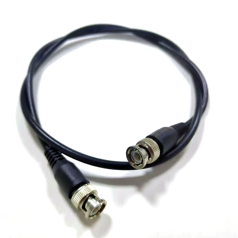
BNC male-to-male coaxial cable assembly designed for connecting RF instruments, receivers, test panels, and other BNC-equipped devices. A flexible cable can reduce mechanical stress compared with a long rigid adapter, but its impedance, insertion loss, cable type, and frequency range must be confirmed.
Mechanical inspection should come before VNA testing.
A damaged center contact, loose body, worn bayonet sleeve, or poorly machined thread can produce unstable measurements and damage the mating connector. A part can pass a multimeter test and still have poor geometry, excessive reflection, or unstable insertion loss at the upper operating frequency.
For VNA acceptance:
- Define the calibration reference planes.
- Remove unnecessary adapters from the test setup.
- Use the correct system impedance.
- Sweep the full required frequency range.
- Record return loss or VSWR.
- Record insertion loss.
- Disconnect and remate the adapter.
- Repeat the measurement.
- Compare multiple production samples.
A practical acceptance table may look like this:
| Test Item | Method | Acceptance Requirement |
| Interface gender | Drawing and visual check | Matches approved drawing |
| Center continuity | DMM | Pass |
| Shell continuity | DMM | Pass |
| Center-to-shell isolation | Resistance test | Meets project limit |
| Thread engagement | Mating test | Smooth, no cross-threading |
| BNC retention | Mate and rotate | Secure lock |
| Body looseness | Manual inspection | No movement |
| Return loss | VNA sweep | Project-defined minimum |
| VSWR | VNA sweep | Project-defined maximum |
| Insertion loss | VNA sweep | Project-defined maximum |
| Remating variation | Repeated VNA test | Within project tolerance |
Keysight’s 11854A Type-N to BNC accessory kit also demonstrates the use of these interface combinations in controlled 50-ohm measurement systems.
Which RFQ Fields Prevent the Wrong Build?
A useful RFQ does not need to be long, but it must close the main interpretation gaps.
The interface description should state both connector families and both genders. Mechanical, electrical, and environmental requirements should then be listed separately.
Use a block such as:
The RFQ should also state whether substitution is allowed. A supplier may offer a product with the same connector ends but a different body length, plating, dielectric, frequency rating, or impedance. Those differences may matter even when the part mates correctly.
For production projects, include packaging and labeling requirements.
Choose an impedance-matching solution when the two systems do not share the same nominal impedance. A normal N-to-BNC adapter should not be treated as a transformer, balun, or matching network.
Choose a different connector strategy when long-term maintenance matters more than short-term convenience. Systems become easier to service when antenna paths use one standard interface and laboratory paths use another clearly defined interface.
Possible improvements include:
- Standardizing antenna feeder connections as N-type
- Standardizing low-frequency bench ports as BNC
- Using one-piece cable assemblies
- Eliminating field-installed adapter chains
- Labeling every 50-ohm and 75-ohm port
- Recording adapter configurations in the BOM
- Keeping approved drawings for every gender combination
A physical connection is only the beginning of compatibility. The approved design should also account for electrical limits, mechanical stress, installation conditions, and repeatable production inspection.
FAQ
Is an N-to-BNC adapter electrically directional?
No. A standard passive straight-through adapter normally carries RF signals in either direction. “N to BNC” describes the two connector families, not a fixed transmission direction. The part must still have the correct male or female end for each equipment port.
Can an N-to-BNC adapter connect any BNC instrument to an antenna?
Only when connector gender, impedance, frequency range, power level, and equipment function are compatible. A product may physically connect a BNC instrument to an N-type antenna while still introducing an impedance mismatch or exceeding the instrument port’s frequency or power limit.
Is an N female to BNC male adapter the same as a BNC male to N female adapter?
Yes. Those two descriptions can refer to the same physical connector combination. The order changes, but the interface pair remains N female and BNC male. A drawing should still be used to prevent confusion between equipment ports and mating adapter ends.
Can a 50-ohm N-type connector be used with a 75-ohm BNC port?
The connectors may be joined physically, but the path contains an impedance mismatch. A passive adapter does not convert 50 ohms to 75 ohms. The resulting reflection may be acceptable in some noncritical applications, but it must be evaluated rather than assumed.
Why can a rigid N adapter damage a BNC port?
An N-type adapter and its cable can be larger and heavier than the BNC panel connector. Adapter length creates leverage, while cable weight, stiffness, side pull, and equipment movement increase the bending load at the BNC port.
When is a BNC-to-N cable better than a rigid adapter?
Use a cable assembly when the ports are offset, the N-type cable is heavy, the equipment moves, vibration is present, or the rigid adapter would block nearby connections. A flexible jumper can isolate the instrument port from cable stress.
Which tests should be requested for precision RF use?
Request mechanical and dimensional inspection, continuity, center-to-shell isolation, return loss or VSWR, insertion loss, and remating repeatability. The quotation or test plan should state the required frequency range, calibration reference planes, and acceptance limits.
Final Selection Note
Before ordering an N to BNC adapter, send the supplier the two existing equipment port descriptions, nominal impedance, operating frequency, connected cable, mechanical installation, and required RF test limits.
That information makes it possible to determine whether a rigid adapter is suitable, whether a flexible jumper is safer, and whether the proposed configuration can be approved without relying on appearance alone.
